EP1503477A2 - Rotor pour une machine tournante à reluctance - Google Patents
Rotor pour une machine tournante à reluctance Download PDFInfo
- Publication number
- EP1503477A2 EP1503477A2 EP04010564A EP04010564A EP1503477A2 EP 1503477 A2 EP1503477 A2 EP 1503477A2 EP 04010564 A EP04010564 A EP 04010564A EP 04010564 A EP04010564 A EP 04010564A EP 1503477 A2 EP1503477 A2 EP 1503477A2
- Authority
- EP
- European Patent Office
- Prior art keywords
- rotor
- core
- block
- key
- rotor core
- Prior art date
- Legal status (The legal status is an assumption and is not a legal conclusion. Google has not performed a legal analysis and makes no representation as to the accuracy of the status listed.)
- Granted
Links
- 239000011162 core material Substances 0.000 claims abstract description 70
- 230000037431 insertion Effects 0.000 claims description 22
- 238000003780 insertion Methods 0.000 claims description 22
- 229910000976 Electrical steel Inorganic materials 0.000 description 18
- 230000004907 flux Effects 0.000 description 15
- 230000000694 effects Effects 0.000 description 12
- 238000004804 winding Methods 0.000 description 7
- 238000010276 construction Methods 0.000 description 6
- 230000006698 induction Effects 0.000 description 6
- 230000010355 oscillation Effects 0.000 description 4
- 239000000853 adhesive Substances 0.000 description 3
- 230000009193 crawling Effects 0.000 description 3
- 239000000945 filler Substances 0.000 description 3
- 238000005096 rolling process Methods 0.000 description 3
- QNRATNLHPGXHMA-XZHTYLCXSA-N (r)-(6-ethoxyquinolin-4-yl)-[(2s,4s,5r)-5-ethyl-1-azabicyclo[2.2.2]octan-2-yl]methanol;hydrochloride Chemical compound Cl.C([C@H]([C@H](C1)CC)C2)CN1[C@@H]2[C@H](O)C1=CC=NC2=CC=C(OCC)C=C21 QNRATNLHPGXHMA-XZHTYLCXSA-N 0.000 description 1
- 238000004080 punching Methods 0.000 description 1
Images


Classifications
-
- H—ELECTRICITY
- H02—GENERATION; CONVERSION OR DISTRIBUTION OF ELECTRIC POWER
- H02K—DYNAMO-ELECTRIC MACHINES
- H02K1/00—Details of the magnetic circuit
- H02K1/06—Details of the magnetic circuit characterised by the shape, form or construction
- H02K1/22—Rotating parts of the magnetic circuit
- H02K1/27—Rotor cores with permanent magnets
- H02K1/2706—Inner rotors
- H02K1/272—Inner rotors the magnetisation axis of the magnets being perpendicular to the rotor axis
- H02K1/274—Inner rotors the magnetisation axis of the magnets being perpendicular to the rotor axis the rotor consisting of two or more circumferentially positioned magnets
- H02K1/2753—Inner rotors the magnetisation axis of the magnets being perpendicular to the rotor axis the rotor consisting of two or more circumferentially positioned magnets the rotor consisting of magnets or groups of magnets arranged with alternating polarity
- H02K1/276—Magnets embedded in the magnetic core, e.g. interior permanent magnets [IPM]
- H02K1/2766—Magnets embedded in the magnetic core, e.g. interior permanent magnets [IPM] having a flux concentration effect
-
- H—ELECTRICITY
- H02—GENERATION; CONVERSION OR DISTRIBUTION OF ELECTRIC POWER
- H02K—DYNAMO-ELECTRIC MACHINES
- H02K2201/00—Specific aspects not provided for in the other groups of this subclass relating to the magnetic circuits
- H02K2201/06—Magnetic cores, or permanent magnets characterised by their skew
-
- Y—GENERAL TAGGING OF NEW TECHNOLOGICAL DEVELOPMENTS; GENERAL TAGGING OF CROSS-SECTIONAL TECHNOLOGIES SPANNING OVER SEVERAL SECTIONS OF THE IPC; TECHNICAL SUBJECTS COVERED BY FORMER USPC CROSS-REFERENCE ART COLLECTIONS [XRACs] AND DIGESTS
- Y10—TECHNICAL SUBJECTS COVERED BY FORMER USPC
- Y10T—TECHNICAL SUBJECTS COVERED BY FORMER US CLASSIFICATION
- Y10T29/00—Metal working
- Y10T29/49—Method of mechanical manufacture
- Y10T29/49002—Electrical device making
- Y10T29/49009—Dynamoelectric machine
- Y10T29/49012—Rotor
Definitions
- This invention relates to a rotor for a reluctance type electric rotating machine which can achieve the similar effects to those achieved by skew.
- a reluctance type rotating machine or, for example, a reluctance type rotating machine provided with permanent magnets includes a rotor formed with a magnetic convex portion where a flux is easy to pass (d axis) and a magnetic concave portion where a flux is difficult to pass (q axis) and a permanent magnet which is disposed in a stator provided with a stator winding.
- the magnetic convex portion (d axis) has a high magnetic flux density in an air gap
- the magnetic concave portion (q axis) has a low magnetic flux density in an air gap.
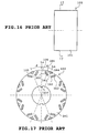
- FIGS. 16 and 17 illustrate an example of conventional rotor for a reluctance type rotating machine with permanent magnets.
- the illustrated machine is an 8-pole machine.
- FIG. 16 is a side view of the rotor with an end plate and a rotational shaft being eliminated.
- FIG. 17 is a sectional view taken along line 17-17.
- the rotor 100 includes a rotor core 101 made by stacking a number of annular silicon steel sheets.
- the rotor core 101 has pairs of generally rectangular magnet insertion holes 102 formed in an outer circumference thereof as shown in FIG. 17. Permanent magnets 103 are inserted and fixed in the insertion holes 102 respectively.
- the outer circumference of the rotor core 101 is further formed with cavities 104 located between the respective pairs of permanent magnets 103 as shown in FIG. 17. Each cavity 104 is formed into a generally triangular shape.
- each pair of insertion holes 102, permanent magnets 103 and each cavity 104 constitute the aforesaid magnetic concave portion 105 where a flux is difficult to pass (q axis).
- Each portion between the concave portions 105 constitutes the aforesaid magnetic convex portion 106 where a flux is easy to pass (d axis).
- the magnetic concave and convex portions 105 and 106 are formed alternately with a predetermined angle therebetween. See JP-A-2000-339922, for example.
- the rotor core 101 has keys 107 formed on an inner circumference thereof.
- the keys 107 are adapted.to engage key grooves of a rotational shaft respectively.
- a center line Lo passing the keys 107 is adapted to pass the center of the magnetic convex portion 106.
- a center line La passes the center of the magnetic convex portion 105 adjacent to the center line Lo.
- the center line Lo is adapted to meet the center line La at an angle ⁇ .
- the angle ⁇ is at 22.5 degrees when the rotor 100 has 8 poles.
- the rotor 100 is adapted to be disposed in a stator (not shown) provided with a stator winding.
- squirrel-cage induction motors result in crawling due to torque developed by high harmonics.
- permanent-magnet reluctance type rotating machines as the reluctance type rotating machine may cause the similar crawling to that caused by the squirrel-cage induction motors.
- the crawling results in torque ripple, oscillation, vibration and noise.
- an object of the present invention is to provide a rotor for a reluctance type rotating machine which can achieve the similar effects to those achieved by skew and reduce torque ripple, oscillation, vibration and noise.
- the present invention provides a rotor for a reluctance type rotating machine comprising a rotor core formed by stacking a number of annular core materials each of which includes magnetic concave and convex portions alternately formed on an outer circumference thereof and a central through hole, the rotor core having a key axially extending on an outer circumference thereof, and a rotational shaft inserted through the central hole of the rotor core , the shaft having a key groove engaging the key of the rotor core.
- the rotor core is divided into a plurality of blocks and the core materials constituting at least one block have the magnetic concave and convex portions shifted by a predetermined angle relative to the core materials constituting the other or another block on the basis of a center line passing the key.
- the core materials constituting at least one block are formed so that the magnetic concave and convex portions are shifted by a predetermined angle from the core materials constituting the other or another block relative to a center line passing the key. Accordingly, for example, a center line passing the center of the magnetic concave portion of at least one block has a locus shifted from one of another or the other block. Consequently, since the similar effects to those achieved by skew can be achieved, the torque ripple, oscillation, vibration and noise can be reduced.
- Each block may include the magnetic concave portions each of which is provided with a pair of magnet insertion holes which are opposed to each other so that a distance therebetween is gradually increased as the insertion holes proceed nearer to the outer circumference of the rotor, and permanent magnets may be inserted and fixed in the insertion holes respectively.
- a magnetic torque by the permanent magnets can also be achieved in addition to reluctance torque. Furthermore,harmonic values of counter electromotive force can be reduced by the similar effects to those achieved by skew.
- FIGS. 1A to 5 illustrate a first embodiment in which the invention is applied to a reluctance type rotating machine with permanent magnets.
- the reluctance type rotating machine possesses eight poles.
- a rotor 1 of the reluctance type rotating machine includes a rotor core 2 made by stacking a number of annular silicon steel sheets serving as a core material.
- the rotor core 2 is divided into four blocks 3 and 4 having the same thickness as shown in FIG. 2.
- the blocks 3 and 4 are stacked alternately.
- Each block 3 or the silicon steel sheets composing each block 3 will be described with reference to FIG. 1A.
- Each block 3 has a number of pairs of generally rectangular magnet insertion holes 5 formed in an outer circumferential portion thereof.
- the paired magnet insertion holes 5 are opposed to each other so that a distance therebetween is gradually increased as the magnet insertion holes 5 near an outer circumferential edge.
- Permanent magnets 6 are inserted into the paired magnet insertion holes 5 respectively and fixed by an adhesive agent, filler or the like.
- the outer circumferential portion of each block 3 also has cavities 7 formed between the permanent magnets 6 of each pair.
- Each cavity 7 is formed into a generally triangular shape having two sides parallel to the paired permanent magnets 6 and the other side extending along the outer circumference. The two sides of each cavity 7 may or may not be parallel to the paired permanent magnets 6.
- Each block 3 includes each portion thereof corresponding to the paired magnet insertion holes 5, permanent magnets 6 and cavity 7 and serving as a magnetic concave portion 8 (q axis) where a flux is difficult to pass.
- Each block 3 further includes each portion thereof located between the magnetic concave portion 8 and serving as a magnetic convex portion 9 (d axis) where a flux is easy to pass.
- the magnetic concave and convex portions 8 and 9 are formed alternately so that each of the magnetic concave and convex portions 8 and 9 meets the other at a predetermined angle.
- Each block 3 further has two keys 10 and 11 which are formed on the inner circumference thereof so as to be 180-degree apart from each other and so as to extend axially.
- a center line Lo passing the centers of the keys 10 and 11 also passes the magnetic convex portions 9 in each block 3.
- the center line Loa forms a predetermined angle ⁇ with a center line Lb passing the center of the magnetic concave portion 8 adjacent to the center line Loa. Accordingly, the center line Loa passes the center of the magnetic convex portion 9.
- the angle ⁇ is represented as 180/n when n is the number of poles of the rotor 1.
- the angle ⁇ is represented as -(60 ⁇ a)/n in degree.
- the minus sign indicates shift in the direction opposite the direction of rotation of the rotor (clockwise).
- Each block 4 or the silicon steel sheets composing each block 4 will be described with reference to FIG. 1B.
- Each block 4 has magnet insertion holes 12 which are similar to the magnet insertion holes 5 and formed in an outer circumferential portion thereof. Permanent magnets 13 are inserted into the paired magnet insertion holes 12 respectively and fixed by an adhesive agent, filler or the like.
- the outer circumferential portion of each block 4 also has cavities 14 which are similar to the cavities 7 and are formed between the permanent magnets 13 of each pair.
- Each block 4 includes each portion thereof corresponding to the paired magnet insertion holes 12, permanent magnets 13 and cavity 14 and serving as a magnetic concave portion 15 (q axis) where a flux is difficult to pass. Each block 4 further includes each portion thereof located between the magnetic concave portion 15 and serving as a magnetic convex portion 16 (d axis) where a flux is easy to pass.
- the magnetic concave and convex portions 8 and 9 are formed alternately so that each of the magnetic concave and convex portions 8 and 9 meets the other at a predetermined angle.
- Each block 4 further has two keys 10 and 11 which are formed on the inner circumference thereof so as to be 180-degree apart from each other and so as to extend axially.
- a center line Lo passing the centers of the keys 10 and 11 also passes the magnetic convex portions 16 in each block 4.
- the center line Lob forms a predetermined angle ⁇ with a center line Lc passing the center of the magnetic concave portion 15 adjacent to the center line Lob. Accordingly, the center line Lob passes the center of the magnetic convex portion 16.
- the angle ⁇ is represented as 180/n when n is the number of poles of the rotor 1.
- the angle ⁇ is represented as + (60 ⁇ a) /n in degree.
- the plus sign indicates deviation in the rotation direction X of the rotor (counterclockwise).
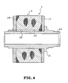
- the block 4 is made by stacking the silicon steel sheets which are the same as those of the block 3 and reversed inside out. Accordingly, the blocks 3 and 4 of the rotor core 2 can be composed of a single type of silicon steel sheets. Two annular end plates 17 and 18 are attached to both ends of the rotor core 2 respectively as shown in FIG. 4.
- the rotating shaft 19, rotor core 2 and end plates 17 and 18 are integrated together by shrinkage fitting thereby to be assembled.
- the keys 10 and 11 of the rotor core 2 are adapted to correspond with key grooves 20 of the rotating shaft 19 respectively. Only one of the key grooves 20 is shown in FIG. 4.
- the rotating shaft 19 is formed with a flange 21 for positioning the rotor core 2 and end plates 17 and 18.
- the magnetic concave and convex portions 8 and 9 of the block 3 are shifted by the predetermined angle ⁇ in the direction opposite the rotation direction X (clockwise) on the basis of the center line Lo. Further, the magnetic concave and convex portions 15 and 16 of the block 4 are also shifted by the predetermined angle ⁇ in the rotation direction X (counterclockwise) on the basis of the center line Lo.
- the center lines Lb and Lc of the blocks 3 and 4 have linear loci which are zigzagged but not straightforward as in the conventional reluctance type rotating machines, as shown in FIG. 3.
- the rotor 1 can achieve the effects similar to those of skew in the rotors for squirrel-cage induction motors.
- an amount of shift is required to be ⁇ 0 between the center lines Lb and the center lines Lc. More specifically, the sum total of a shift angle ⁇ (-) of the center lines Lb and a shift angle ⁇ (+) of the center lines Lc is required to be ⁇ 0 and the sum total of loci lengths of the center lines Lb (total thickness of the block 3) is required to be equal to the sum total of loci lengths of the center lines Lc (total thickness of the block 4) or the difference between both sums is required to be ⁇ 0.
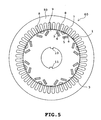
- the permanent-magnet reluctance type rotating machine 60 comprises the rotor 1 disposed in the stator provided with stator winding (not shown) as shown in FIG. 5.
- the rotor 1 includes the magnetic concave portions 8 and 15 (q axis) where a flux is difficult to pass and the magnetic convex portions 9 and 16 (d axis) where a flux is easy to pass.
- magnetic energy is stored in air gaps over the magnetic concave and convex portions 8 and 15, and 9 and 16 respectively.
- the magnetic energy differs from one air gap to another.
- the changes in the magnetic energy develop reluctance torque.
- the magnetic concave and convex portions 8 and 9 of the block 3 are shifted by the predetermined angle ⁇ in the direction opposite the rotation direction X (clockwise) on the basis of the center line Lo. Further, the magnetic concave and convex portions 15 and 16 of the block 4 are also shifted by the predetermined angle ⁇ in the rotation direction X (counterclockwise) on the basis of the center line Lo.
- the linear loci of the center lines Lb and Lc of the blocks 3 and 4 are zigzagged and accordingly, the rotor 1 can achieve the effects similar to those of skew in the rotors for squirrel-cage induction motors. Consequently, torque ripple, oscillation, vibration and noise can be reduced in the permanent-magnet reluctance type rotating machine, and a peak value of back electromotive force can be reduced in the stator winding.
- an amount of shift is set so as to be ⁇ 0 between the center lines Lb and the center lines Lc in the rotor core 2. Consequently, magnetic obstacle can be prevented although the rotor 1 can achieve the effects similar to those of skew in the rotors for squirrel-cage induction motors.
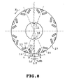
- FIGS. 6 to 8 illustrate a second embodiment of the invention.
- the rotor core 26 employed instead of the rotor core 2 includes blocks 3 and 27 stacked alternately.
- Each block 27 comprises the silicon steel sheets which are the same as those of each block 4 but are reversed by 180 degrees or more specifically, each block 4 is reversed by 180 degrees.
- the other construction of the rotor of the second embodiment is the same as that of the first embodiment.
- the linear loci of the center lines Lb and Lc of the blocks 3 and 27 are zigzagged in the same manner as in the first embodiment. Consequently, the rotor of the second embodiment can achieve the same effects as those of the first embodiment.
- the annular silicon steel sheets constituting the rotor core 26 are formed by punching a rolled elongated silicon steel sheet. It is well known that the rolling results in shift in the thickness in the rolling direction and in the direction perpendicular to the rolling direction. In the second embodiment, however, the blocks 27 obtained by reversing the blocks 4 by 180 degrees. Consequently, since the deviation in the thickness is absorbed, the thickness of the rotor core 26 can be rendered uniform.
- the thicknesses of the four blocks 3 and 27 are equal to one another in the second embodiment.
- the total thickness of the blocks having the respective center lines Lb may be equal to the total thickness of the blocks having the respective center lines Lc.
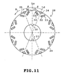
- FIGS. 9 to 11 illustrate a third embodiment of the invention. Describing the difference of the third embodiment from the first embodiment, the rotor core 28 employed instead of the rotor core 2 is divided into four blocks 29, 30 and 31. Each block 29 has a thickness set to be equal to or less than one half of that of each of blocks 30 and 31. The thickness of each block 29 is set at one half of that of each of the blocks 30 and 31 in the embodiment.
- the block 30 is formed by stacking the same silicon steel sheets as those of each block 4 (see FIG. 1B) .
- the block 31 is formed by stacking the same silicon steel sheets as those of each block 3 (see FIG. 1A).
- the block 30 has a thickness equal to one of the block 31 and larger than the blocks 3 and 4.
- the rotor core 28 has a thickness equal to that of the rotor core 2.
- Each block 29 or the silicon steel sheets composing each block 29 will be described with reference to FIG. 11.
- Each block 29 has a number of pairs of generally rectangular magnet insertion holes 32 which are formed in an outer circumferential portion thereof and are similar to the insertion holes 5.
- the permanent magnets 33 are inserted into the paired magnet insertion holes 32 respectively and fixed by an adhesive agent, filler or the like.
- the outer circumferential portion of each block 29 also has cavities 34 which are formed between the permanent magnets 33 of each pair and are similar to the cavities 7.
- Each block 29 includes each portion thereof corresponding to the paired magnet insertion holes 32, permanent magnets 33 and cavity 34 and serving as the magnetic concave portion 35 (q axis) where a flux is difficult to pass.
- Each block 29 further includes each portion thereof located between the magnetic concave portion 35 and serving as a magnetic convex portion 36 (d axis) where a flux is easy to pass.
- the magnetic concave and convex portions 35 and 36 are formed alternately with a predetermined angle therebetween.
- Each block 29 further has two keys 10 and 11 which are formed on the inner circumference thereof so as to be 180-degree apart from each other and so as to extend axially.
- the center line Lo passing the centers of the keys 10 and 11 also passes the magnetic convex portions 36 in each block 29.
- the center line Lo forms a predetermined angle ⁇ with a center line Ld passing the center of the magnetic concave portion 35 adjacent to the center line Lo.
- the angle ⁇ is represented as 180/n when n is the number of poles of the rotor 1.
- the silicon steel sheets constituting each block 29 are similar to those employed in the conventional rotor core as shown in FIG. 17.
- the center lines Lb and Lc of the blocks 31 and 30 have linear loci which are zigzagged. Accordingly, the rotor can achieve the effects similar to those of skew in the rotors for squirrel-cage induction motors as in the first embodiment.
- the center lines Ld of the blocks 29 located at both ends of the rotor core 28 have loci are located between the loci of the center lines Lc and Lb. Accordingly, since the mechanical balance can be improved between the rotor core 28 and the stator winding, the waveform characteristic of the back electromotive force can be improved in the stator winding.
- FIGS. 12 and 13 illustrate a fourth embodiment of the invention.
- the difference of the fourth embodiment from the first embodiment will be described.
- the rotor core 39 employed instead of the rotor core 2 includes a block 40 formed by integrating the blocks 3 and a block 41 formed by integrating the blocks 4.
- the loci of the center lines Lb and Lc of the respective blocks 40 and 41 are as shown in FIG. 13. Accordingly, the fourth embodiment can achieve the same effects as those of the first embodiment.
- FIGS. 14 and 15 illustrate a fifth embodiment of the invention.
- the difference of the fifth embodiment from the fourth embodiment will be described.
- the rotor core 42 employed in the fifth embodiment includes blocks 43 and 44.
- One half 44a of the block 44 is formed by stacking the silicon steel sheets (see FIG. 1B) which are the same as those of the block 41.
- the other half 44b of the block 44 is formed by stacking the silicon steel sheets (see FIG. 8) which are the same as those of the block 27.
- one half 43a of the block 43 is formed by stacking the silicon steel sheets (FIG. 1A) which are the same as those of the block 40.
- the other half 43b is formed by reversing by 180 degrees and stacking the silicon steel sheets which are the same as those of the block 40 or more specifically, by reversing the portion 43a by 180 degrees.
- the other construction of the rotor of the fifth embodiment is the same as that of the first embodiment. Consequently, the fifth embodiment can achieve the same effects as those of the fourth and second embodiments.
- the portions 43a and 43b and the portions 44a and 44b constituting the respective blocks 43 and 44 are set at one halves of the thicknesses of the blocks 43 and 44 respectively in the fifth embodiment. However, these portions may be set substantially at one halves respectively.
- the permanent magnets are provided on the rotor core in each of the foregoing embodiments.
- the permanent magnets may or may not be provided on the rotor core.
- the generally triangular cavities are formed in the rotor core so as to compose the concave and convex portions in each of the foregoing embodiments.
- the cavities may be circular, elliptic, rectangular or rhombic.
- the rotor core may have mechanical concave and convex portions formed therein so that the magnetic concave and convex portions are formed.
- the number of poles of the rotor should not be limited to eight. The same effect can be achieved even when the number of poles is any other number. Furthermore, the number of slots of the stator may be set at any suitable number. Additionally, the number of blocks of the rotor should not be limited to two and four. Five or more blocks may be provided by stacking the silicon steel sheets having the magnetic concave and convex portions shifted. In this case, an amount of shift of the center line is required to be ⁇ 0.
Landscapes
- Engineering & Computer Science (AREA)
- Power Engineering (AREA)
- Permanent Field Magnets Of Synchronous Machinery (AREA)
- Iron Core Of Rotating Electric Machines (AREA)
- Synchronous Machinery (AREA)
- Permanent Magnet Type Synchronous Machine (AREA)
Applications Claiming Priority (2)
| Application Number | Priority Date | Filing Date | Title |
|---|---|---|---|
| JP2003204863A JP4070673B2 (ja) | 2003-07-31 | 2003-07-31 | リラクタンス型回転電機の回転子 |
| JP2003204863 | 2003-07-31 |
Publications (3)
| Publication Number | Publication Date |
|---|---|
| EP1503477A2 true EP1503477A2 (fr) | 2005-02-02 |
| EP1503477A3 EP1503477A3 (fr) | 2007-11-28 |
| EP1503477B1 EP1503477B1 (fr) | 2018-08-15 |
Family
ID=33535627
Family Applications (1)
| Application Number | Title | Priority Date | Filing Date |
|---|---|---|---|
| EP04010564.5A Expired - Lifetime EP1503477B1 (fr) | 2003-07-31 | 2004-05-04 | Machine tournante à reluctance |
Country Status (4)
| Country | Link |
|---|---|
| US (1) | US7170209B2 (fr) |
| EP (1) | EP1503477B1 (fr) |
| JP (1) | JP4070673B2 (fr) |
| CN (1) | CN100353645C (fr) |
Families Citing this family (35)
| Publication number | Priority date | Publication date | Assignee | Title |
|---|---|---|---|---|
| JP4102749B2 (ja) * | 2003-12-24 | 2008-06-18 | オークマ株式会社 | リラクタンスモータの回転子 |
| JP4449035B2 (ja) * | 2004-03-10 | 2010-04-14 | 日立オートモティブシステムズ株式会社 | 電動車両用の永久磁石回転電機 |
| JP2005335535A (ja) * | 2004-05-27 | 2005-12-08 | Sanyo Electric Co Ltd | 電動車輪用ハブユニット及び該ハブユニットを具えた乗物 |
| DE102005047771A1 (de) * | 2005-10-05 | 2007-04-19 | Minebea Co., Ltd. | Rotoranordnung für eine elektrische Maschine und Verfahren zum Herstellen der Rotoranordnung |
| JP4856990B2 (ja) * | 2006-03-13 | 2012-01-18 | トヨタ自動車株式会社 | ロータおよびその製造方法ならびに電動車両 |
| US7385328B2 (en) * | 2006-05-23 | 2008-06-10 | Reliance Electric Technologies, Llc | Cogging reduction in permanent magnet machines |
| JP5288698B2 (ja) * | 2006-10-20 | 2013-09-11 | 株式会社東芝 | 永久磁石式リラクタンス型回転電機 |
| JP4908178B2 (ja) * | 2006-12-15 | 2012-04-04 | 東芝産業機器製造株式会社 | 回転電機 |
| US7791236B2 (en) * | 2007-08-16 | 2010-09-07 | Ford Global Technologies, Llc | Permanent magnet machine |
| JP4492681B2 (ja) * | 2007-11-16 | 2010-06-30 | 株式会社デンソー | 同期機 |
| US20100117475A1 (en) * | 2008-11-11 | 2010-05-13 | Ford Global Technologies, Llc | Permanent Magnet Machine with Offset Pole Spacing |
| GB2508971B (en) * | 2008-11-11 | 2014-12-03 | Ford Global Tech Llc | Permanent magnet machine with offset pole spacing |
| US8536748B2 (en) * | 2008-11-11 | 2013-09-17 | Ford Global Technologies, Llc | Permanent magnet machine with different pole arc angles |
| JP5434415B2 (ja) * | 2009-09-14 | 2014-03-05 | 株式会社豊田自動織機 | 永久磁石埋設型回転電機 |
| US8461739B2 (en) * | 2009-09-25 | 2013-06-11 | Ford Global Technologies, Llc | Stator for an electric machine |
| JP2011167055A (ja) | 2010-01-14 | 2011-08-25 | Yaskawa Electric Corp | 永久磁石形同期回転電機の回転子、当該永久磁石形同期回転電機、当該永久磁石形同期回転電機を用いた車両、昇降機、流体機械、または加工機 |
| JP5495045B2 (ja) * | 2010-05-12 | 2014-05-21 | 株式会社デンソー | 回転電機の回転子 |
| US9705388B2 (en) | 2011-12-19 | 2017-07-11 | Baldor Electric Company | Rotor for a line start permanent magnet machine |
| CN102738928A (zh) * | 2012-04-24 | 2012-10-17 | 重庆通赛机电有限公司 | 无刷驱动电机转子 |
| JP6137521B2 (ja) * | 2012-09-27 | 2017-05-31 | 株式会社デンソー | 回転電機 |
| JP5892106B2 (ja) * | 2013-04-15 | 2016-03-23 | 株式会社安川電機 | 回転電機及び回転子の製造方法 |
| TWI516000B (zh) * | 2013-08-20 | 2016-01-01 | 林聖梁 | 馬達 |
| KR101461924B1 (ko) * | 2013-12-18 | 2014-11-17 | 현대자동차 주식회사 | 모터의 회전자 코어 및 그 회전자 코어의 결합유닛 |
| JP2016073056A (ja) * | 2014-09-29 | 2016-05-09 | トヨタ自動車株式会社 | ロータの製造方法 |
| KR101736553B1 (ko) * | 2014-12-05 | 2017-05-30 | 주식회사 포스코 | 회전자 및 이를 포함하는 영구자석형 모터 |
| CN204858787U (zh) * | 2015-07-30 | 2015-12-09 | 中山大洋电机股份有限公司 | 一种转子冲片及其应用的永磁电机 |
| JP6486492B2 (ja) * | 2015-10-27 | 2019-03-20 | 三菱電機株式会社 | ロータ、永久磁石埋込型電動機および圧縮機 |
| KR101736051B1 (ko) * | 2015-10-30 | 2017-05-18 | 전자부품연구원 | 회전자 및 이를 포함하는 영구자석형 전동기 |
| CN105871097B (zh) * | 2016-06-06 | 2018-11-20 | 上海川也电机有限公司 | 电动汽车电机的低波动永磁转子 |
| FR3067880B1 (fr) * | 2017-06-15 | 2020-07-17 | Moteurs Leroy-Somer | Machine electrique tournante |
| TWM576750U (zh) | 2017-07-25 | 2019-04-11 | 美商米沃奇電子工具公司 | 電氣組合物、電動化裝置系統、電池組、電馬達、馬達總成及電馬達總成 |
| CN216398138U (zh) | 2019-02-18 | 2022-04-29 | 米沃奇电动工具公司 | 冲击工具 |
| CN112436629B (zh) * | 2019-08-26 | 2021-11-16 | 安徽美芝精密制造有限公司 | 转子、电机、压缩机及制冷设备 |
| KR102613923B1 (ko) * | 2021-11-19 | 2023-12-13 | 김병국 | 초고속 전동기 |
| CN114285199A (zh) * | 2021-12-27 | 2022-04-05 | 浙江盘毂动力科技有限公司 | 一种磁阻式轴向磁通电机转子及成型方法 |
Citations (2)
| Publication number | Priority date | Publication date | Assignee | Title |
|---|---|---|---|---|
| JPH1118339A (ja) | 1997-06-27 | 1999-01-22 | Aisin Aw Co Ltd | モータ |
| JP2001339922A (ja) | 2000-05-24 | 2001-12-07 | Toshiba Corp | 永久磁石式リラクタンス型回転電機 |
Family Cites Families (14)
| Publication number | Priority date | Publication date | Assignee | Title |
|---|---|---|---|---|
| US4833353A (en) * | 1987-11-09 | 1989-05-23 | Ram Air Manufacturing | Method of optimizing armature balance through lamination orientation |
| JP3493865B2 (ja) * | 1995-12-27 | 2004-02-03 | アイシン・エィ・ダブリュ株式会社 | モータ |
| JPH09327140A (ja) * | 1996-06-07 | 1997-12-16 | Hitachi Ltd | 永久磁石回転型回転電機及びその製造方法 |
| JP3857017B2 (ja) * | 2000-03-30 | 2006-12-13 | 株式会社東芝 | 永久磁石式リラクタンス型回転電機 |
| JP3819211B2 (ja) * | 2000-03-31 | 2006-09-06 | 株式会社東芝 | 永久磁石式リラクタンス型回転電機 |
| JP2001314050A (ja) * | 2000-04-27 | 2001-11-09 | Sony Corp | Acサーボ・モータ |
| JP2002165428A (ja) * | 2000-11-20 | 2002-06-07 | Toshiba Transport Eng Inc | 同期型回転機及び永久磁石型リラクタンスモータ |
| JP4013487B2 (ja) * | 2001-02-28 | 2007-11-28 | 株式会社日立製作所 | 回転電機及びそれを搭載した車両 |
| JP2003009483A (ja) * | 2001-06-21 | 2003-01-10 | Sumitomo Heavy Ind Ltd | 永久磁石埋込み型誘導電動機 |
| JP3885732B2 (ja) * | 2003-01-07 | 2007-02-28 | 日産自動車株式会社 | 永久磁石埋め込み同期モータ |
| US6906443B2 (en) * | 2003-04-21 | 2005-06-14 | Eaton Corporation | Brushless DC motor with stepped skewed rotor |
| US7129611B2 (en) * | 2003-05-22 | 2006-10-31 | Ut-Battelle Llc | Method and radial gap machine for high strength undiffused brushless operation |
| US6867524B2 (en) * | 2003-06-04 | 2005-03-15 | Ford Global Technologies, Llc | Rotor skew methods for permanent magnet motors |
| JP4070674B2 (ja) * | 2003-07-31 | 2008-04-02 | 株式会社東芝 | リラクタンス型回転電機の回転子 |
-
2003
- 2003-07-31 JP JP2003204863A patent/JP4070673B2/ja not_active Expired - Lifetime
-
2004
- 2004-04-28 US US10/833,095 patent/US7170209B2/en not_active Expired - Lifetime
- 2004-05-04 EP EP04010564.5A patent/EP1503477B1/fr not_active Expired - Lifetime
- 2004-05-10 CN CNB2004100385617A patent/CN100353645C/zh not_active Expired - Lifetime
Patent Citations (3)
| Publication number | Priority date | Publication date | Assignee | Title |
|---|---|---|---|---|
| JPH1118339A (ja) | 1997-06-27 | 1999-01-22 | Aisin Aw Co Ltd | モータ |
| JP2001339922A (ja) | 2000-05-24 | 2001-12-07 | Toshiba Corp | 永久磁石式リラクタンス型回転電機 |
| US20020109429A1 (en) | 2000-05-24 | 2002-08-15 | Tomoyuki Hattori | Permanent magnet type electric motor |
Also Published As
| Publication number | Publication date |
|---|---|
| JP2005051896A (ja) | 2005-02-24 |
| US7170209B2 (en) | 2007-01-30 |
| EP1503477B1 (fr) | 2018-08-15 |
| CN1581642A (zh) | 2005-02-16 |
| JP4070673B2 (ja) | 2008-04-02 |
| CN100353645C (zh) | 2007-12-05 |
| US20050023922A1 (en) | 2005-02-03 |
| EP1503477A3 (fr) | 2007-11-28 |
Similar Documents
| Publication | Publication Date | Title |
|---|---|---|
| EP1503477A2 (fr) | Rotor pour une machine tournante à reluctance | |
| US7057322B2 (en) | Rotor for reluctance type rotating machine | |
| KR101880377B1 (ko) | 영구 자석 매립형 회전 전기 기기 | |
| KR100609330B1 (ko) | 영구자석 회전자형 전동기 | |
| JP3906882B2 (ja) | 永久磁石電動機 | |
| JP5589345B2 (ja) | 永久磁石式回転電機 | |
| US6104117A (en) | Motor with reduced clogging torque incorporating stator salient poles and rotor magnetic poles | |
| US7528519B2 (en) | Permanent magnet rotary motor | |
| US7233089B2 (en) | Permanent magnet rotating electric machine | |
| JP5813254B2 (ja) | 永久磁石式回転電機 | |
| JP3906883B2 (ja) | 永久磁石電動機 | |
| US7276832B2 (en) | Permanent magnet rotary motor | |
| US20110050022A1 (en) | Permanent magnet buried type electric motor | |
| KR20080077128A (ko) | 영구 여기된 전기 기계의 회전자 박판들의 배치 | |
| JP2008199794A (ja) | 埋込磁石型モータ | |
| JP3769943B2 (ja) | 永久磁石ロータ | |
| JP2000253608A (ja) | ブラシレスモータ | |
| KR100655994B1 (ko) | 서보 모터용 로터의 조립구조 | |
| JPH04156243A (ja) | 永久磁石回転子 | |
| JP3598804B2 (ja) | 電動機のロータ | |
| JP3914293B2 (ja) | 永久磁石モータ | |
| JP2020182358A (ja) | 回転電機の回転子 | |
| KR0137575Y1 (ko) | 동기형 ac 서보모터의 로터 | |
| JP5352442B2 (ja) | 永久磁石モータ | |
| JP6853335B2 (ja) | ステータおよび回転電機 |
Legal Events
| Date | Code | Title | Description |
|---|---|---|---|
| PUAI | Public reference made under article 153(3) epc to a published international application that has entered the european phase |
Free format text: ORIGINAL CODE: 0009012 |
|
| 17P | Request for examination filed |
Effective date: 20040504 |
|
| AK | Designated contracting states |
Kind code of ref document: A2 Designated state(s): AT BE BG CH CY CZ DE DK EE ES FI FR GB GR HU IE IT LI LU MC NL PL PT RO SE SI SK TR |
|
| AX | Request for extension of the european patent |
Extension state: AL HR LT LV MK |
|
| PUAL | Search report despatched |
Free format text: ORIGINAL CODE: 0009013 |
|
| AK | Designated contracting states |
Kind code of ref document: A3 Designated state(s): AT BE BG CH CY CZ DE DK EE ES FI FR GB GR HU IE IT LI LU MC NL PL PT RO SE SI SK TR |
|
| AX | Request for extension of the european patent |
Extension state: AL HR LT LV MK |
|
| AKX | Designation fees paid |
Designated state(s): DE FR GB IT |
|
| 17Q | First examination report despatched |
Effective date: 20100301 |
|
| GRAP | Despatch of communication of intention to grant a patent |
Free format text: ORIGINAL CODE: EPIDOSNIGR1 |
|
| INTG | Intention to grant announced |
Effective date: 20180409 |
|
| RIN1 | Information on inventor provided before grant (corrected) |
Inventor name: KAZAO, YUKIHIKO Inventor name: AIKURA, NOBUTAKE Inventor name: ARATA, MASANORI Inventor name: HIRANO, YASUO Inventor name: MOCHIZUKI, MOTOYASU Inventor name: OHASHI, MASANORI Inventor name: HANAI, TAKASHI Inventor name: MATSUBARA, MASAKATSU Inventor name: YAMASHIKI, MASAHIKO Inventor name: ARAKI, TAKESHI Inventor name: KONDOU, AKITO |
|
| INTG | Intention to grant announced |
Effective date: 20180412 |
|
| GRAS | Grant fee paid |
Free format text: ORIGINAL CODE: EPIDOSNIGR3 |
|
| GRAA | (expected) grant |
Free format text: ORIGINAL CODE: 0009210 |
|
| RAP1 | Party data changed (applicant data changed or rights of an application transferred) |
Owner name: TOSHIBA INDUSTRIAL PRODUCTS MANUFACTURING CORPORAT Owner name: KABUSHIKI KAISHA TOSHIBA |
|
| AK | Designated contracting states |
Kind code of ref document: B1 Designated state(s): DE FR GB IT |
|
| REG | Reference to a national code |
Ref country code: GB Ref legal event code: FG4D |
|
| REG | Reference to a national code |
Ref country code: DE Ref legal event code: R096 Ref document number: 602004053040 Country of ref document: DE |
|
| REG | Reference to a national code |
Ref country code: DE Ref legal event code: R097 Ref document number: 602004053040 Country of ref document: DE |
|
| PLBE | No opposition filed within time limit |
Free format text: ORIGINAL CODE: 0009261 |
|
| STAA | Information on the status of an ep patent application or granted ep patent |
Free format text: STATUS: NO OPPOSITION FILED WITHIN TIME LIMIT |
|
| 26N | No opposition filed |
Effective date: 20190516 |
|
| GBPC | Gb: european patent ceased through non-payment of renewal fee |
Effective date: 20190504 |
|
| PG25 | Lapsed in a contracting state [announced via postgrant information from national office to epo] |
Ref country code: GB Free format text: LAPSE BECAUSE OF NON-PAYMENT OF DUE FEES Effective date: 20190504 |
|
| REG | Reference to a national code |
Ref country code: FR Ref legal event code: PLFP Year of fee payment: 20 |
|
| PGFP | Annual fee paid to national office [announced via postgrant information from national office to epo] |
Ref country code: IT Payment date: 20230412 Year of fee payment: 20 Ref country code: FR Payment date: 20230411 Year of fee payment: 20 Ref country code: DE Payment date: 20230331 Year of fee payment: 20 |
|
| REG | Reference to a national code |
Ref country code: DE Ref legal event code: R071 Ref document number: 602004053040 Country of ref document: DE |