EP1503221A1 - Détecteur de distance à balayage - Google Patents
Détecteur de distance à balayage Download PDFInfo
- Publication number
- EP1503221A1 EP1503221A1 EP04018274A EP04018274A EP1503221A1 EP 1503221 A1 EP1503221 A1 EP 1503221A1 EP 04018274 A EP04018274 A EP 04018274A EP 04018274 A EP04018274 A EP 04018274A EP 1503221 A1 EP1503221 A1 EP 1503221A1
- Authority
- EP
- European Patent Office
- Prior art keywords
- rotary member
- scanning
- light
- rotational axis
- range sensor
- Prior art date
- Legal status (The legal status is an assumption and is not a legal conclusion. Google has not performed a legal analysis and makes no representation as to the accuracy of the status listed.)
- Granted
Links
Images


Classifications
-
- G—PHYSICS
- G01—MEASURING; TESTING
- G01S—RADIO DIRECTION-FINDING; RADIO NAVIGATION; DETERMINING DISTANCE OR VELOCITY BY USE OF RADIO WAVES; LOCATING OR PRESENCE-DETECTING BY USE OF THE REFLECTION OR RERADIATION OF RADIO WAVES; ANALOGOUS ARRANGEMENTS USING OTHER WAVES
- G01S7/00—Details of systems according to groups G01S13/00, G01S15/00, G01S17/00
- G01S7/48—Details of systems according to groups G01S13/00, G01S15/00, G01S17/00 of systems according to group G01S17/00
- G01S7/481—Constructional features, e.g. arrangements of optical elements
- G01S7/4817—Constructional features, e.g. arrangements of optical elements relating to scanning
-
- G—PHYSICS
- G01—MEASURING; TESTING
- G01C—MEASURING DISTANCES, LEVELS OR BEARINGS; SURVEYING; NAVIGATION; GYROSCOPIC INSTRUMENTS; PHOTOGRAMMETRY OR VIDEOGRAMMETRY
- G01C15/00—Surveying instruments or accessories not provided for in groups G01C1/00 - G01C13/00
- G01C15/002—Active optical surveying means
-
- G—PHYSICS
- G01—MEASURING; TESTING
- G01S—RADIO DIRECTION-FINDING; RADIO NAVIGATION; DETERMINING DISTANCE OR VELOCITY BY USE OF RADIO WAVES; LOCATING OR PRESENCE-DETECTING BY USE OF THE REFLECTION OR RERADIATION OF RADIO WAVES; ANALOGOUS ARRANGEMENTS USING OTHER WAVES
- G01S17/00—Systems using the reflection or reradiation of electromagnetic waves other than radio waves, e.g. lidar systems
- G01S17/02—Systems using the reflection of electromagnetic waves other than radio waves
- G01S17/06—Systems determining position data of a target
- G01S17/42—Simultaneous measurement of distance and other co-ordinates
-
- G—PHYSICS
- G01—MEASURING; TESTING
- G01S—RADIO DIRECTION-FINDING; RADIO NAVIGATION; DETERMINING DISTANCE OR VELOCITY BY USE OF RADIO WAVES; LOCATING OR PRESENCE-DETECTING BY USE OF THE REFLECTION OR RERADIATION OF RADIO WAVES; ANALOGOUS ARRANGEMENTS USING OTHER WAVES
- G01S7/00—Details of systems according to groups G01S13/00, G01S15/00, G01S17/00
- G01S7/48—Details of systems according to groups G01S13/00, G01S15/00, G01S17/00 of systems according to group G01S17/00
- G01S7/481—Constructional features, e.g. arrangements of optical elements
- G01S7/4811—Constructional features, e.g. arrangements of optical elements common to transmitter and receiver
- G01S7/4813—Housing arrangements
-
- G—PHYSICS
- G01—MEASURING; TESTING
- G01S—RADIO DIRECTION-FINDING; RADIO NAVIGATION; DETERMINING DISTANCE OR VELOCITY BY USE OF RADIO WAVES; LOCATING OR PRESENCE-DETECTING BY USE OF THE REFLECTION OR RERADIATION OF RADIO WAVES; ANALOGOUS ARRANGEMENTS USING OTHER WAVES
- G01S17/00—Systems using the reflection or reradiation of electromagnetic waves other than radio waves, e.g. lidar systems
- G01S17/88—Lidar systems specially adapted for specific applications
- G01S17/93—Lidar systems specially adapted for specific applications for anti-collision purposes
- G01S17/931—Lidar systems specially adapted for specific applications for anti-collision purposes of land vehicles
Definitions
- the present invention relates to so-called scanning range sensors, which use a rotating or vibrating mirror or an equivalent to scan an object with a light beam within a predetermined angle range, and which receive light reflected by the object.
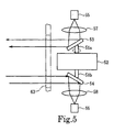
- a scanning range sensor that uses a rotating mirror for deflecting the axis of an optical beam over a full, 360-degree range of angles. Both configurations have a mirror whose optical axis coincides with the axis of a motor for rotating the mirror.
- the configuration shown in Fig. 5 uses a motor 52 having rotary shafts 51a and 51b that constitute a common shaft and extend upward and downward, respectively.
- a scanning mirror 53 and a reflecting mirror 54 are attached to respective shafts 51a and 51b so as to have identical phase.
- At numeral 55 in Fig. 5 is a light transmitter
- at numeral 56 is a photodetector
- at numerals 57 and 58 are lenses
- at numeral 63 is a light exit/entrance window 63.
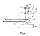
- the sensor section of the scanning range sensor configuration shown in Fig. 6 has a motor 52 with a rotary shaft 51c protruding upward and a light scanning/reflecting mirror 59 that is attached to the rotary shaft 51c.
- Light from the light transmitter 55 passes through a lens 60, is reflected downward by a half-silvered mirror 61, and enters the scanning/reflecting mirror 59.
- This reflected light is reflected by the scanning/reflecting mirror 59, passes through the half-silvered mirror 61, passes through a lens 62, and enters the photodetector 56.
- the motor 52 is positioned between the scanning mirror 53 and the reflecting mirror 54, the distance between the optical axes of the scanning optics and the receiving optics is large. Therefore, if a target object is positioned within close range, light reflected from the object does not enter the photodetector 56, resulting in the occurrence of a blind spot.
- the center of the two optical systems is coincident with the center of the sensor. Therefore, when installing the vertically elongate sensor in a device, its center must be the optical axis. This limits the degrees of freedom for installation in a device.
- a drawback is that the outward-extending portions are large.
- the half-silvered mirror 61 is employed to make the optical axes of the scanning optics and the receiving optics identical to each other.
- the amount of light is reduced by half after being separated by the half-silvered mirror 61. Therefore, the power of the laser in the light transmitter 55, and the amplifying capability of the photodetector 56 must be enhanced by four times in total compared with an implementation in which the scanning optics and the receiving optics are separated as shown in Fig. 5.
- the fact that the single scanning/reflecting mirror 59 is used means that the scanning beam may be reflected by the inner surface of, or by dust particles on, the light e-xit/entrance window 63, in which case the stray reflected light can enter the photodetector 56 after being transmitted by the scanning/reflecting mirror 59 and passing through the half-silvered mirror 61. If the photodetector 56 is of enhanced photosensitivity, the stray reflected light may generate noise that becomes added to image information. Consequently, the photosensitivity cannot be heightened without compensating for it.
- An object of the present invention is to shorten the distance between the optical axis of the beam projected from a scanning range sensor toward an object and the optical axis of light reflected by the object into the sensor, thus to make it possible to prevent the sensor from having a blind spot even when the distance from the sensor to the object is short.
- Another object of the present invention is to separate the scanning optical system from the receiving optical system, thus to make it possible to prevent the sensor from being disturbed by noise due to stray light reflected by the transmitting and receiving windows or by dust particles on the transmitting and receiving windows, to allow the photosensitivity of the sensor to be enhanced.
- a scanning range sensor in one aspect of the present invention has a structure including: a light receiving section situated on or near a stationary shaft of the motor, in a location where the center of the light receiving section coincides with the rotational axis of the motor; a rotary component having, surrounding the light receiving section, an top wall portion and a circumferential wall potion; and a motor drive mechanism for driving the rotary component.
- a scanning optical system for generating a scanning beam directed on the sensing target, and a receiving optical system for guiding to the light receiving section light reflected by the object are provided individually on the top wall portion of the rotary component.
- the scanning mirror and the reflecting mirror are constructed as entities separate from each other.
- scanning and receiving windows are provided along and in the circumferential wall potion of the rotary component for passing the scanning beam and the reflected light.
- the top wall portion and the circumferential wall portion not only may be walls constituted by boards having a close-packed structure, but also, for example, by mesh constructed with support columns extending along the rotational axis and radially.
- Another scanning sensor has the following structure in addition to the above structure. Namely, image signals obtained by the light receiving section go through space inside the stationary shaft of the motor and are led to an external computation circuit. Then, in order to calculate the position or related information on the object from the image signal, a motor rotational position signal is also led to the external computation circuit via the inside of the motor stationary shaft.
- the scanning mirror and the reflecting mirror are configured for being connected directly to the rotary shaft of the motor as shown in Fig. 5 and Fig. 6. For this reason, there was no alternative to separating the scanning optical system from the receiving optical system on the upper and the lower sides of the motor, or to integrating them by using a half-silvered mirror.
- Adopting a configuration according to the present aspect of the invention makes it possible to dispose the photodetector and the light projector to one side of the motor without using a half-silvered mirror.
- the scanning and receiving optical systems can be integrated, while a scanning range sensor in which the distance between the optical axis of the beam projected from the sensor toward an object and the optical axis of light reflected by the object into the sensor is short can be realized.
- the light receiving section can be structured by disposing a photoelectric conversion element where the light receiving section is situated, or by collecting the received light and through an optical fiber or the like sending the collected light to another unit for carrying out photoelectric conversion and other processes.
- a representative application of a scanning sensor according to the present invention is as a visual sensor for a robot or the like.
- the scanning optical axis and the receiving optical axis extend substantially horizontally.
- the motor rotary shaft on the other hand extends substantially vertically. At least the light reflected by the reflecting mirror is guided along the rotational axis of the motor to the light receiving section.
- the scanning beam is emitted by the light projector (a light source) provided separately and is guided along the rotational axis of the motor so that the scanning mirror disposed on the top wall portion of the rotary component converts the orientation of the scanning beam into substantially horizontal.
- the present invention has the following effects.
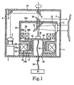
- a vertically cylindrical outer cover 1 houses a main body of a scanning range sensor.
- the outer cover 1 is placed on the top of the head portion of the robot.
- the outer cover 1 is made of an appropriate material such as a synthetic resin.
- a transparent window 2 that has a horizontally annular form and a uniform vertical width is formed slightly above center.
- This transparent window 2 may be made of a transparent, annularly seamless, band-shaped constituent separate from the main material of the outer cover 1 and set into position as the transparent window.
- the outer cover 1 itself may be formed integrally of a transparent material, and then a portion except for the transparent window may be painted. Note that it is possible to make the entire of the outer cover 1 transparent so that the area of the transparent window is widened to the entirety. In that case, however, it would be necessary to prevent undesired external light from entering the photodetector.
- a light projector 3 is arranged at a position adjacent to the inner surface of the circumferential wall of the outer cover 1 so as to project light vertically upward.
- This light projector 3 has a light source such as a laser or an LED.
- An optical lens 4 for making the diameter of the beam constant is disposed at the upper end of the light projector 3.
- a first mirror 5 is fixed to the inner surface of the top plate 1a of the outer cover 1 and is positioned right above the light projector 3, while a second mirror 6 is fixed to the center position of the inner surface of the same top plate 1a.
- These mirrors 5 and 6 are arranged so that the first mirror 5 is inclined to the right ⁇ in terms of the orientation of the drawing ⁇ approximately 45 degrees from the vertical direction and the second mirror 6 is inclined to the left approximately 45 degrees.
- a cylindrical rotary member 10 is disposed in the outer cover 1 at a position shifted a little to the right in the Fig. 1 representation.
- This cylindrical rotary member 10 is made of an appropriate material such as a synthetic resin, and a light receiving window 11 having a circular shape is formed at an upper portion of the circumferential wall.
- An optical lens 12 is fixed into this light receiving window 11 and is adjusted so that its optical axis coincides with the radius there of the cylindrical rotary member 10.
- the lower portion of the cylindrical rotary member 10 has a rotating-member lower end portion 10b that has a reduced outer diameter. Meanwhile, a motor 15 is disposed in the bottom portion of the outer cover 1.
- This motor 15 includes a stator 15a having a winding coil and a core, a cylindrical portion 16 along the inner circumferential surface of which the stator 15a is fixed, a base plate portion 17 that is disposed in parallel with the bottom portion of the outer cover so as to form an inner bottom surface of the cylindrical portion 16, a motor stationary shaft 19 that is formed in the center of the base plate portion 17, and a horizontal disk portion 20 that is fixed to the upper end of the stationary shaft 19.
- a hollow through-hole 18 is proved inside the motor stationary shaft 19 so as to extend in the vertical direction.
- An inner circumferential surface of a bearing 21 is fixedly fitted to an outer cylindrical surface of the motor stationary shaft 19, and an inner cylindrical surface of the rotating-member lower end portion 10b of the cylindrical rotary member 10 is rotatably engaged with the outer circumferential surface of the bearing 21.
- the bearing 21 can be a ball bearing or a slide bearing, for example.
- magnets 22 are attached to the outside cylindrical surface of the rotary member lower end portion 10b so as to face the stator 15a via a slight gap.
- An external power source (not shown) supplies the stator 15a with a switching current so that a rotating magnetic field is generated in the stator's inner cylindrical space.
- This rotating magnetic field and the magnets 22 that are disposed at the lower end outer circumferential portion of the cylindrical rotary member 10 are attracted by each other, wherein a rotary drive force is generated between them.
- this motor is not limited to being a brushless DC motor but may be a synchronous motor or the like.
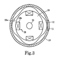
- a photodetector 25 is disposed along the rotational axis of the motor on the upper surface of the disk portion 20 as shown in Figs. 1 and 3.
- This photodetector 25 is constituted by an optical sensor such as a photodiode, and the focal point of the optical lens 12 is adjusted to lie on the photodetector 25.
- the photodetector 25 is connected via a signal wire 26 to a distance computation circuit 27 that is disposed outside the outer cover 1 (in a control portion of the guarding robot or cleaning robot).
- a resolver 28 is arranged surrounding the photodetector 25 on the upper surface of the disk portion 20 for detecting precisely the rotational angle of the cylindrical rotary member 10.
- This resolver 28 includes: an undulating surface 28a as a rotor, made of a magnetic material and being, e.g., four smooth contours formed along the circuit of the inner circumferential surface of the cylindrical rotary member 10; and a resolver stator 28b opposed to the undulating surface 28a and having windings along the upper outer circumferential surface of the disk portion 20.
- an undulating surface 28a as a rotor, made of a magnetic material and being, e.g., four smooth contours formed along the circuit of the inner circumferential surface of the cylindrical rotary member 10
- a resolver stator 28b opposed to the undulating surface 28a and having windings along the upper outer circumferential surface of the disk portion 20.
- a simpler rotational position detector can be realized by providing a mechanism for generating a pulse per rotation of the cylindrical rotary member, and by dividing the pulse signal using a PLL circuit. In that case, the resolver 28 would not be necessary.
- the mechanism for generating the pulse may be realized by providing a Hall sensor at a position that is adjacent to the magnet 22 on the base plate portion 17 or by placing a photoreceptor in the vicinity of the transparent window 2 for the transmitted light, for example.
- a scanning mirror 30 and a reflecting mirror 31 are attached to the top plate portion 10a of the cylindrical rotary member 10 so that the optical axes thereof coincide with the rotational axis.
- the scanning mirror 30 and the reflecting mirror 31 are disposed so as to incline respectively to the left and the right by approximately 45 degrees each from the vertical.
- the beam from the light projector 3 is reflected by the second mirror 6 downward and is incident on the scanning mirror 30 with the optical axis coincident with the rotational axis. Then, the reflected light is radiated substantially in the horizontal direction, to outside the cylindrical rotary member 10 in the radial direction.
- the scanning mirror 30 rotates at a high speed together with the cylindrical rotary member 10. Therefore, a beam having been projected by the light projector 3 and reflected by the scanning mirror 30 after passing through the first mirror 5 and the second mirror 6 is scanned continuously over the entire circuit of peripheral space through the transparent window 2 in the outer cover 1, so as to scan external objects continuously. Then, the light reflected by the objects enters the outer cover 1 through the transparent window 2 to be incident on the reflecting mirror 31 substantially in the horizontal direction after passing through the optical lens 12 in the light receiving window 11.
- the light is reflected downward along the rotational axis by the reflecting mirror 31, and is focused on the photodetector 25, which converts quanta of the light into an electric signal (a phase signal).
- This electric signal is sent to the distance computation circuit 27 via the signal wire 26.
- the resolver 28b detects the rotational angle of the cylindrical rotary member 10 when the photodetector 25 receives the light, and information on the rotational angle is also sent to the distance computation circuit 27 via the signal wire 26.
- the distance computation circuit 27 calculates the distance to the objects in accordance with the phase signal and generates a plane two-dimensional map by combining the distance and the rotational angle information from the resolver 28.
- a scanning range sensor can be realized that has an outer shape much smaller and more compact than the conventional one by the effective and close arrangement of the motor and the optical system.
- the light projector is disposed inside the outer cover, and the beam from the light projector is reflected by the mirror on the inner surface of the outer cover so as to enter the scanning mirror of the rotary member along the direction of the rotational axis.
- the scanning optics is completely separate from the receiving optics, so that reflected light arising in the scanning optics does not enter the receiving optics. This configuration is advantageous for allowing photosensitivity to be increased.
- the scanning angle of the beam must be precisely detected scanning over 360 degrees.
- polar teeth are provided on the cylindrical rotary member of the resolver for detecting the rotational angle, and the stator of the resolver is supported together with the photodetector.
- the rotational angle of the cylindrical rotary member can be detected precisely, and the cylindrical rotary member has only optical elements such as its mirror and polar teeth of the resolver, which do not require electricity. Therefore, durability and reliability of the range sensor can be improved substantially.
- a second embodiment of the present invention will be described with reference to Fig. 4.
- This example is a variation in which the light projector 3 is arranged on the disk portion 20 inside the cylindrical rotary member 10. Because a half-silvered mirror 35 is used, if a laser is used as a light source, the photosensitivity must be limited for safety by restricting the output power. On the other hand, however, a significant advantage to this configuration is that the vertical height of the scanning range sensor can be further decreased because it is possible to eliminate the mirrors 5 and 6 on the inner surface of the outer cover 1 shown in Fig. 1. In Fig.
- the beam reflected upward by the half-silvered mirror 35 is incident upon the lower surface of the scanning mirror 36 through a tiny optical through-hole 37 in the center of the reflecting mirror 31, and a tiny optical through-hole 38 in the center of the top plate portion 10a of the cylindrical rotary member 10 along the rotational axis of the cylindrical rotary member 10.
- the scanning mirror 36 is inclined to the right of the vertical by approximately 45 degrees, so that a beam incident on the scanning mirror 36 from directly below is reflected substantially in the horizontal direction to exit the transparent window 2.
- the remainder of the configuration is similar to that shown in Fig. 1.
- a beam from the light projector 3 passes through the half-silvered mirror 35, the optical through-hole 37 and the optical through-hole 38, is deflected by the scanning mirror 36 and passes through the transparent window 2 to enter peripheral space; meanwhile light reflected from objects passes through the transparent window 2 and the optical lens 12, is reflected by the reflecting mirror 31 and passes through the half-silvered mirror 35 to be received by the photodetector 25.
- Generation of the two-dimensional map after that is the same as described above with reference to Fig. 1.
- the photosensitivity is lowered a little because a half-silvered mirror is used.
- the scanning light and receiving light are separated from each other, there is no possibility that an inwardly reflected component of the scanning light will enter the photodetector.
- the range sensor can be made more compact because the light projector is disposed inside the cylindrical rotary member.
- the height of the range sensor can be further decreased because it is not necessary to attach a mirror to the inside of the outer cover.
- the above-described light projector typically uses a laser as the light source, it is possible to use an LED as the light source.
- a laser has little dispersion of light, and thus can pass through a narrow path easily. Therefore, the shape of the sensor can be minimized.
- an LED instead of a laser, it is better to use an LED that can be modulated at high frequency.
- An LED is more advantageous than a laser because an LED has a larger light spot than a laser, which is limited in power for safety reasons.
- the AM modulation method is a method in which laser light or LED light is modulated at a constant frequency, and the distance is determined from the difference between the phase of the modulated signal and the phase of light reflected by an object. Namely, if a beam that is modulated at a frequency f is reflected by an object and comes back, the return beam will have a phase difference ⁇ that is determined by the speed of light and the distance. The value of the phase difference ⁇ depends on the speed of light c and the distance L. Therefore, if the phase difference ⁇ is detected, the distance L can be determined.
- distance measurements within a two-dimensional area can be performed.
- the present invention can be applied to a two-dimensional range sensor.
- distance measurements within a three-dimensional region are also possible by scanning the scanning beam over a 360-degree circuit while continuously increasing or decreasing the vertical angle of the scanning mirror.
- peripheral space may be scanned by the beam in a helical fashion, for example.
- a scanning range sensor of the present invention is not limited to these embodiments, but various modifications can be added to the examples within the scope of the present invention.
- the motors in the foregoing embodiments are considered to rotate in one direction at a constant speed, it is possible to control the motor 15 to rotate reversibly within a predetermined angle range.
- the range sensor scans an object only through a predetermined span that is an extension of the outer circumference. Furthermore, it is possible to realize wide angle scanning over a wide range vertically, i.e., three-dimensional scanning, by inclining and vibrating the entire sensor including the outer cover 1 around the rotational axis of the motor 15 with a predetermined periodicity.
Applications Claiming Priority (2)
| Application Number | Priority Date | Filing Date | Title |
|---|---|---|---|
| JP2003284441A JP3875665B2 (ja) | 2003-07-31 | 2003-07-31 | スキャニング型レンジセンサ |
| JP2003284441 | 2003-07-31 |
Publications (2)
| Publication Number | Publication Date |
|---|---|
| EP1503221A1 true EP1503221A1 (fr) | 2005-02-02 |
| EP1503221B1 EP1503221B1 (fr) | 2009-04-29 |
Family
ID=33535720
Family Applications (1)
| Application Number | Title | Priority Date | Filing Date |
|---|---|---|---|
| EP04018274A Expired - Fee Related EP1503221B1 (fr) | 2003-07-31 | 2004-08-02 | Détecteur de distance à balayage |
Country Status (5)
| Country | Link |
|---|---|
| US (1) | US7136153B2 (fr) |
| EP (1) | EP1503221B1 (fr) |
| JP (1) | JP3875665B2 (fr) |
| CN (1) | CN1278098C (fr) |
| DE (1) | DE602004020843D1 (fr) |
Cited By (16)
| Publication number | Priority date | Publication date | Assignee | Title |
|---|---|---|---|---|
| WO2008059279A1 (fr) * | 2006-11-18 | 2008-05-22 | Stephen George Nunney | Procédé et dispositif permettant de mesurer une distance |
| WO2009035887A2 (fr) * | 2007-09-10 | 2009-03-19 | Trimble Navigation Limited | Emetteur laser rotatif |
| EP1956391A3 (fr) * | 2007-02-06 | 2010-01-06 | Denso Wave Incorporated | Appareil de radar laser qui mesure la direction et la distance d'un objet |
| EP2375266A1 (fr) * | 2010-04-09 | 2011-10-12 | Sick AG | Capteur optoélectronique et procédé de sécurisation |
| CN101770031B (zh) * | 2010-01-15 | 2012-09-05 | 北京航空航天大学 | 一种基于半环反射镜的全效二维激光测距仪 |
| EP2645125A1 (fr) | 2012-03-27 | 2013-10-02 | Sick AG | Capteur optoélectronique et procédé destiné à la détection d'objets dans une zone de surveillance |
| CN107209265A (zh) * | 2015-03-20 | 2017-09-26 | 摸索科技有限公司 | 光探测和测距装置 |
| US20180267147A1 (en) * | 2015-04-28 | 2018-09-20 | Korea Electronics Technology Institute | Multi-channel lidar scanner optical system using mirror rotation manner |
| EP3447524A1 (fr) * | 2017-08-21 | 2019-02-27 | Yujin Robot Co., Ltd. | Capteur lidar de balayage tridimensionnel compact |
| EP3492949A1 (fr) * | 2017-11-30 | 2019-06-05 | Faltec Co., Ltd. | Couvercle de lidar |
| CN110118959A (zh) * | 2018-02-06 | 2019-08-13 | 西克股份公司 | 检测监测区域中的对象的光电传感器和方法 |
| CN111279212A (zh) * | 2019-01-09 | 2020-06-12 | 深圳市大疆创新科技有限公司 | 扫描模组、测距装置及移动平台 |
| US10962647B2 (en) | 2016-11-30 | 2021-03-30 | Yujin Robot Co., Ltd. | Lidar apparatus based on time of flight and moving object |
| EP3712643A4 (fr) * | 2017-11-13 | 2021-06-23 | Hangzhou United Tools Co., Ltd. | Dispositif de télémétrie laser |
| US11579298B2 (en) | 2017-09-20 | 2023-02-14 | Yujin Robot Co., Ltd. | Hybrid sensor and compact Lidar sensor |
| US11874399B2 (en) | 2018-05-16 | 2024-01-16 | Yujin Robot Co., Ltd. | 3D scanning LIDAR sensor |
Families Citing this family (78)
| Publication number | Priority date | Publication date | Assignee | Title |
|---|---|---|---|---|
| JP3908226B2 (ja) * | 2004-02-04 | 2007-04-25 | 日本電産株式会社 | スキャニング型レンジセンサ |
| JP3935897B2 (ja) * | 2004-06-15 | 2007-06-27 | 北陽電機株式会社 | 光波測距装置 |
| DE102005043931A1 (de) * | 2005-09-15 | 2007-03-29 | Fraunhofer-Gesellschaft zur Förderung der angewandten Forschung e.V. | Laserscanner |
| JP2007108009A (ja) * | 2005-10-13 | 2007-04-26 | Hokuyo Automatic Co | 光学装置 |
| DE102006022733A1 (de) * | 2006-05-12 | 2007-11-15 | Fraunhofer-Gesellschaft zur Förderung der angewandten Forschung e.V. | Schneller Doppelscanner für Hochgeschwindigkeitsprofilometer |
| DE102006031580A1 (de) | 2006-07-03 | 2008-01-17 | Faro Technologies, Inc., Lake Mary | Verfahren und Vorrichtung zum dreidimensionalen Erfassen eines Raumbereichs |
| JP5056362B2 (ja) * | 2007-02-06 | 2012-10-24 | 株式会社デンソーウェーブ | レーザレーダ装置 |
| JP5181628B2 (ja) * | 2007-11-12 | 2013-04-10 | 株式会社デンソーウェーブ | レーザレーダ装置 |
| JP5348449B2 (ja) * | 2007-12-25 | 2013-11-20 | カシオ計算機株式会社 | 距離測定装置及びプロジェクタ |
| JP4579321B2 (ja) * | 2008-08-29 | 2010-11-10 | 株式会社日本自動車部品総合研究所 | 位置検出装置 |
| DE102009010465B3 (de) | 2009-02-13 | 2010-05-27 | Faro Technologies, Inc., Lake Mary | Laserscanner |
| US9551575B2 (en) | 2009-03-25 | 2017-01-24 | Faro Technologies, Inc. | Laser scanner having a multi-color light source and real-time color receiver |
| DE102009015920B4 (de) | 2009-03-25 | 2014-11-20 | Faro Technologies, Inc. | Vorrichtung zum optischen Abtasten und Vermessen einer Umgebung |
| DE102009035337A1 (de) | 2009-07-22 | 2011-01-27 | Faro Technologies, Inc., Lake Mary | Verfahren zum optischen Abtasten und Vermessen eines Objekts |
| JP2011099816A (ja) | 2009-11-09 | 2011-05-19 | Sony Corp | 集光レンズ及び3次元距離測定装置 |
| US9529083B2 (en) | 2009-11-20 | 2016-12-27 | Faro Technologies, Inc. | Three-dimensional scanner with enhanced spectroscopic energy detector |
| US9210288B2 (en) | 2009-11-20 | 2015-12-08 | Faro Technologies, Inc. | Three-dimensional scanner with dichroic beam splitters to capture a variety of signals |
| DE102009055988B3 (de) | 2009-11-20 | 2011-03-17 | Faro Technologies, Inc., Lake Mary | Vorrichtung zum optischen Abtasten und Vermessen einer Umgebung |
| US9113023B2 (en) | 2009-11-20 | 2015-08-18 | Faro Technologies, Inc. | Three-dimensional scanner with spectroscopic energy detector |
| DE102009055989B4 (de) | 2009-11-20 | 2017-02-16 | Faro Technologies, Inc. | Vorrichtung zum optischen Abtasten und Vermessen einer Umgebung |
| DE102009057101A1 (de) | 2009-11-20 | 2011-05-26 | Faro Technologies, Inc., Lake Mary | Vorrichtung zum optischen Abtasten und Vermessen einer Umgebung |
| JP5488099B2 (ja) * | 2009-12-08 | 2014-05-14 | 株式会社デンソーウェーブ | レーザレーダ装置 |
| US9163922B2 (en) | 2010-01-20 | 2015-10-20 | Faro Technologies, Inc. | Coordinate measurement machine with distance meter and camera to determine dimensions within camera images |
| US9879976B2 (en) | 2010-01-20 | 2018-01-30 | Faro Technologies, Inc. | Articulated arm coordinate measurement machine that uses a 2D camera to determine 3D coordinates of smoothly continuous edge features |
| US9607239B2 (en) | 2010-01-20 | 2017-03-28 | Faro Technologies, Inc. | Articulated arm coordinate measurement machine having a 2D camera and method of obtaining 3D representations |
| JP5192614B1 (ja) | 2010-01-20 | 2013-05-08 | ファロ テクノロジーズ インコーポレーテッド | 座標測定デバイス |
| US9628775B2 (en) | 2010-01-20 | 2017-04-18 | Faro Technologies, Inc. | Articulated arm coordinate measurement machine having a 2D camera and method of obtaining 3D representations |
| DE102010020925B4 (de) | 2010-05-10 | 2014-02-27 | Faro Technologies, Inc. | Verfahren zum optischen Abtasten und Vermessen einer Umgebung |
| DE102010032723B3 (de) | 2010-07-26 | 2011-11-24 | Faro Technologies, Inc. | Vorrichtung zum optischen Abtasten und Vermessen einer Umgebung |
| DE102010032726B3 (de) | 2010-07-26 | 2011-11-24 | Faro Technologies, Inc. | Vorrichtung zum optischen Abtasten und Vermessen einer Umgebung |
| DE102010032725B4 (de) | 2010-07-26 | 2012-04-26 | Faro Technologies, Inc. | Vorrichtung zum optischen Abtasten und Vermessen einer Umgebung |
| US9168654B2 (en) | 2010-11-16 | 2015-10-27 | Faro Technologies, Inc. | Coordinate measuring machines with dual layer arm |
| DE102012100609A1 (de) | 2012-01-25 | 2013-07-25 | Faro Technologies, Inc. | Vorrichtung zum optischen Abtasten und Vermessen einer Umgebung |
| US8997362B2 (en) | 2012-07-17 | 2015-04-07 | Faro Technologies, Inc. | Portable articulated arm coordinate measuring machine with optical communications bus |
| JP2014052366A (ja) * | 2012-08-06 | 2014-03-20 | Ricoh Co Ltd | 光計測装置、車両 |
| DE102012107544B3 (de) | 2012-08-17 | 2013-05-23 | Faro Technologies, Inc. | Vorrichtung zum optischen Abtasten und Vermessen einer Umgebung |
| US10067231B2 (en) | 2012-10-05 | 2018-09-04 | Faro Technologies, Inc. | Registration calculation of three-dimensional scanner data performed between scans based on measurements by two-dimensional scanner |
| DE102012109481A1 (de) | 2012-10-05 | 2014-04-10 | Faro Technologies, Inc. | Vorrichtung zum optischen Abtasten und Vermessen einer Umgebung |
| US9513107B2 (en) | 2012-10-05 | 2016-12-06 | Faro Technologies, Inc. | Registration calculation between three-dimensional (3D) scans based on two-dimensional (2D) scan data from a 3D scanner |
| JP6069628B2 (ja) * | 2012-12-03 | 2017-02-01 | 北陽電機株式会社 | 偏向装置、光走査装置及び走査式測距装置 |
| US20150120555A1 (en) * | 2013-10-29 | 2015-04-30 | Elwha Llc | Exchange authorization analysis infused with network-acquired data stream information |
| CN104655097B (zh) * | 2013-11-21 | 2017-04-19 | 科沃斯机器人股份有限公司 | 激光测距传感器及其测距方法 |
| JP5582432B1 (ja) * | 2014-02-17 | 2014-09-03 | 健 中西 | 螺旋状走査機構及び三次元測位装置 |
| JP5620603B1 (ja) * | 2014-03-31 | 2014-11-05 | 中西 健 | 螺旋状走査機構及び三次元測位装置 |
| EP3035076B1 (fr) * | 2014-12-17 | 2020-08-19 | Leica Geosystems AG | Dispositif de mesure doté d'un dispositif de positionnement |
| TWM506280U (zh) | 2015-03-20 | 2015-08-01 | Arima Lasers Corp | 旋轉光學測距裝置 |
| CN105987686B (zh) * | 2015-08-13 | 2019-03-05 | 小米科技有限责任公司 | 激光测距设备、无线通信方法及装置 |
| JP6892734B2 (ja) * | 2015-12-15 | 2021-06-23 | 株式会社トプコン | 光波距離測定装置 |
| DE102015122844A1 (de) | 2015-12-27 | 2017-06-29 | Faro Technologies, Inc. | 3D-Messvorrichtung mit Batteriepack |
| CN105738912A (zh) * | 2016-02-05 | 2016-07-06 | 上海思岚科技有限公司 | 一种激光测距设备 |
| JP6673716B2 (ja) * | 2016-02-22 | 2020-03-25 | 株式会社キーエンス | 安全スキャナ |
| CN105807283A (zh) * | 2016-04-01 | 2016-07-27 | 上海思岚科技有限公司 | 一种激光扫描测距装置及其移动机器人 |
| EP3447521B1 (fr) * | 2016-04-20 | 2019-12-18 | Konica Minolta, Inc. | Capteur laser et procédé de fabrication d'un constituant extérieur |
| CN106019293A (zh) * | 2016-05-19 | 2016-10-12 | 上海思岚科技有限公司 | 一种激光扫描测距装置 |
| US11034335B2 (en) * | 2016-07-07 | 2021-06-15 | Nio Usa, Inc. | Low-profile imaging system with enhanced viewing angles |
| KR101978049B1 (ko) * | 2016-08-30 | 2019-05-14 | 한양대학교 산학협력단 | ToF 카메라 장치 |
| DE102016118471A1 (de) * | 2016-09-29 | 2018-03-29 | Valeo Schalter Und Sensoren Gmbh | Erfassungsvorrichtung für ein Kraftfahrzeug, Anbauteil sowie Kraftfahrzeug |
| CN107942337A (zh) * | 2016-10-13 | 2018-04-20 | 北京飞思迈尔光电科技有限公司 | 一种光学扫描传感器 |
| KR101924266B1 (ko) * | 2016-12-14 | 2018-11-30 | 전자부품연구원 | 라이다 장치 |
| DE102017101945A1 (de) * | 2017-02-01 | 2018-08-02 | Osram Opto Semiconductors Gmbh | Messanordnung mit einem optischen Sender und einem optischen Empfänger |
| JP2018169546A (ja) * | 2017-03-30 | 2018-11-01 | 日本電産株式会社 | ハウジング、ハウジングユニット、およびケーシングユニット |
| JP2019012104A (ja) * | 2017-06-29 | 2019-01-24 | 日本電産株式会社 | ハウジングおよびハウジングユニット |
| CN109387850A (zh) * | 2017-08-02 | 2019-02-26 | 松下知识产权经营株式会社 | 距离测定装置 |
| KR102065640B1 (ko) * | 2017-12-05 | 2020-01-13 | 광주과학기술원 | 라이다 장치 |
| JP7035558B2 (ja) * | 2018-01-24 | 2022-03-15 | 株式会社デンソー | ライダー装置 |
| CN110235025B (zh) * | 2018-04-28 | 2023-08-04 | 深圳市大疆创新科技有限公司 | 距离探测装置 |
| DE102018116132A1 (de) | 2018-07-04 | 2020-01-09 | Minebea Mitsumi Inc. | Strahlablenkeinrichtung für einen optischen Scanner |
| CN110873868A (zh) * | 2018-08-31 | 2020-03-10 | 探维科技(北京)有限公司 | 基于mems扫描镜的激光雷达系统 |
| CN110873867A (zh) * | 2018-08-31 | 2020-03-10 | 探维科技(北京)有限公司 | 基于mems扫描镜的激光雷达系统 |
| KR102280497B1 (ko) * | 2018-09-04 | 2021-07-21 | 현대모비스 주식회사 | 라이다 센서 조립체 |
| JP6867736B2 (ja) * | 2018-09-21 | 2021-05-12 | 株式会社トプコン | 光波距離測定装置 |
| CN109282754B (zh) * | 2018-10-19 | 2020-09-25 | 嘉善美源服饰水洗有限公司 | 一种大范围3d激光探测扫描装置 |
| US11460578B2 (en) * | 2018-12-28 | 2022-10-04 | Robert Bosch Gmbh | 3D lidar sensing unit with oscillating axis of rotation for autonomous driving |
| CN111279219A (zh) * | 2019-01-09 | 2020-06-12 | 深圳市大疆创新科技有限公司 | 扫描模组、测距装置及移动平台 |
| KR102299264B1 (ko) * | 2019-01-16 | 2021-09-07 | 삼성전자주식회사 | 라이다 장치 |
| US11137485B2 (en) * | 2019-08-06 | 2021-10-05 | Waymo Llc | Window occlusion imager near focal plane |
| CN111090082A (zh) * | 2019-08-30 | 2020-05-01 | 上海禾赛光电科技有限公司 | 激光雷达和利用其进行探测的方法 |
| US20220121035A1 (en) * | 2020-10-15 | 2022-04-21 | Raytheon Company | OPTICAL SENSOR WITH Tx/Rx APERTURE SHARING ELEMENT (ASE) FOR PROCESSING PASSIVE AND ACTIVE SIGNALS |
Citations (4)
| Publication number | Priority date | Publication date | Assignee | Title |
|---|---|---|---|---|
| US3813140A (en) * | 1971-12-13 | 1974-05-28 | Bendix Corp | Rotating prism scanning system having range compensation |
| JPH07191142A (ja) * | 1993-12-27 | 1995-07-28 | Astecs Kk | 全方位距離検出装置 |
| US5808727A (en) * | 1996-10-29 | 1998-09-15 | Mitsubishi Denki Kabushiki Kaisha | Vehicle optical radar apparatus |
| US20010035946A1 (en) * | 1998-11-24 | 2001-11-01 | Hamamatsu Photonics K.K | Light-projecting/receiving unit and omnidirectional distance detecting apparatus |
Family Cites Families (11)
| Publication number | Priority date | Publication date | Assignee | Title |
|---|---|---|---|---|
| JPS62254008A (ja) | 1986-04-04 | 1987-11-05 | Toshihiro Tsumura | 移動体の位置検出装置 |
| US5455669A (en) | 1992-12-08 | 1995-10-03 | Erwin Sick Gmbh Optik-Elektronik | Laser range finding apparatus |
| US5416321A (en) * | 1993-04-08 | 1995-05-16 | Coleman Research Corporation | Integrated apparatus for mapping and characterizing the chemical composition of surfaces |
| JPH07209080A (ja) | 1993-12-28 | 1995-08-11 | Amberg Measuring Technik Ltd | 光学走査装置 |
| DE19607345A1 (de) | 1996-02-27 | 1997-08-28 | Sick Ag | Laserabstandsermittlungsvorrichtung |
| DE19647152A1 (de) | 1996-11-14 | 1998-05-28 | Sick Ag | Laserabstandsermittlungsvorrichtung |
| JP3417278B2 (ja) | 1997-12-04 | 2003-06-16 | 日産自動車株式会社 | レーザ式測距装置 |
| JP2002506977A (ja) | 1998-03-10 | 2002-03-05 | リーグル・レーザー・メジャーメント・システムズ・ゲゼルシャフト・ミト・ベシュレンクテル・ハフツング | 被写体又は被写体空間を監視する方法 |
| JP2000028715A (ja) | 1998-07-14 | 2000-01-28 | Nippon Signal Co Ltd:The | 複合形レーダセンサ |
| DE19917509C1 (de) | 1999-04-17 | 2000-05-25 | Leuze Electronic Gmbh & Co | Optoelektronische Vorrichtung |
| DE10002090A1 (de) | 2000-01-19 | 2001-07-26 | Sick Ag | Optische Abtastvorrichtung |
-
2003
- 2003-07-31 JP JP2003284441A patent/JP3875665B2/ja not_active Expired - Lifetime
-
2004
- 2004-07-30 US US10/710,726 patent/US7136153B2/en active Active
- 2004-07-30 CN CNB2004100557806A patent/CN1278098C/zh active Active
- 2004-08-02 DE DE602004020843T patent/DE602004020843D1/de active Active
- 2004-08-02 EP EP04018274A patent/EP1503221B1/fr not_active Expired - Fee Related
Patent Citations (4)
| Publication number | Priority date | Publication date | Assignee | Title |
|---|---|---|---|---|
| US3813140A (en) * | 1971-12-13 | 1974-05-28 | Bendix Corp | Rotating prism scanning system having range compensation |
| JPH07191142A (ja) * | 1993-12-27 | 1995-07-28 | Astecs Kk | 全方位距離検出装置 |
| US5808727A (en) * | 1996-10-29 | 1998-09-15 | Mitsubishi Denki Kabushiki Kaisha | Vehicle optical radar apparatus |
| US20010035946A1 (en) * | 1998-11-24 | 2001-11-01 | Hamamatsu Photonics K.K | Light-projecting/receiving unit and omnidirectional distance detecting apparatus |
Non-Patent Citations (1)
| Title |
|---|
| PATENT ABSTRACTS OF JAPAN vol. 1995, no. 10 30 November 1995 (1995-11-30) * |
Cited By (27)
| Publication number | Priority date | Publication date | Assignee | Title |
|---|---|---|---|---|
| WO2008059279A1 (fr) * | 2006-11-18 | 2008-05-22 | Stephen George Nunney | Procédé et dispositif permettant de mesurer une distance |
| EP1956391A3 (fr) * | 2007-02-06 | 2010-01-06 | Denso Wave Incorporated | Appareil de radar laser qui mesure la direction et la distance d'un objet |
| WO2009035887A2 (fr) * | 2007-09-10 | 2009-03-19 | Trimble Navigation Limited | Emetteur laser rotatif |
| WO2009035887A3 (fr) * | 2007-09-10 | 2009-04-30 | Trimble Navigation Ltd | Emetteur laser rotatif |
| US7587832B2 (en) | 2007-09-10 | 2009-09-15 | Trimble Navigation Limited | Rotating laser transmitter |
| US7954246B2 (en) | 2007-09-10 | 2011-06-07 | Trimble Navigation Limited | Rotating laser transmitter |
| CN101770031B (zh) * | 2010-01-15 | 2012-09-05 | 北京航空航天大学 | 一种基于半环反射镜的全效二维激光测距仪 |
| EP2375266A1 (fr) * | 2010-04-09 | 2011-10-12 | Sick AG | Capteur optoélectronique et procédé de sécurisation |
| EP2645125A1 (fr) | 2012-03-27 | 2013-10-02 | Sick AG | Capteur optoélectronique et procédé destiné à la détection d'objets dans une zone de surveillance |
| EP3273267A4 (fr) * | 2015-03-20 | 2018-12-19 | Msotek Inc. | Dispositif lidar |
| CN107209265B (zh) * | 2015-03-20 | 2022-10-11 | 摸索科技有限公司 | 光探测和测距装置 |
| CN107209265A (zh) * | 2015-03-20 | 2017-09-26 | 摸索科技有限公司 | 光探测和测距装置 |
| EP3290986A4 (fr) * | 2015-04-28 | 2018-12-19 | Korea Electronics Technology Institute | Système optique de balayage lidar multicanal utilisant une sorte de rotation de miroir |
| US10670702B2 (en) | 2015-04-28 | 2020-06-02 | Korea Electronics Technology Institute | Multi-channel lidar scanner optical system using mirror rotation manner |
| US20180267147A1 (en) * | 2015-04-28 | 2018-09-20 | Korea Electronics Technology Institute | Multi-channel lidar scanner optical system using mirror rotation manner |
| US10962647B2 (en) | 2016-11-30 | 2021-03-30 | Yujin Robot Co., Ltd. | Lidar apparatus based on time of flight and moving object |
| EP3447524A1 (fr) * | 2017-08-21 | 2019-02-27 | Yujin Robot Co., Ltd. | Capteur lidar de balayage tridimensionnel compact |
| US11579298B2 (en) | 2017-09-20 | 2023-02-14 | Yujin Robot Co., Ltd. | Hybrid sensor and compact Lidar sensor |
| US11604276B2 (en) | 2017-11-13 | 2023-03-14 | Hangzhou United Tools Co., Ltd. | Laser ranging apparatus |
| EP3712643A4 (fr) * | 2017-11-13 | 2021-06-23 | Hangzhou United Tools Co., Ltd. | Dispositif de télémétrie laser |
| EP3492949A1 (fr) * | 2017-11-30 | 2019-06-05 | Faltec Co., Ltd. | Couvercle de lidar |
| US11480707B2 (en) | 2018-02-06 | 2022-10-25 | Sick Ag | Optoelectronic sensor and method of detecting objects in a monitoring zone |
| EP3521858A3 (fr) * | 2018-02-06 | 2019-12-18 | Sick AG | Capteur optoélectronique et procédé de détection d'objets dans une zone de surveillance |
| CN110118959A (zh) * | 2018-02-06 | 2019-08-13 | 西克股份公司 | 检测监测区域中的对象的光电传感器和方法 |
| US11874399B2 (en) | 2018-05-16 | 2024-01-16 | Yujin Robot Co., Ltd. | 3D scanning LIDAR sensor |
| CN111279212A (zh) * | 2019-01-09 | 2020-06-12 | 深圳市大疆创新科技有限公司 | 扫描模组、测距装置及移动平台 |
| CN111279212B (zh) * | 2019-01-09 | 2024-02-13 | 深圳市大疆创新科技有限公司 | 扫描模组、测距装置及移动平台 |
Also Published As
| Publication number | Publication date |
|---|---|
| US20050024625A1 (en) | 2005-02-03 |
| CN1580691A (zh) | 2005-02-16 |
| DE602004020843D1 (de) | 2009-06-10 |
| JP3875665B2 (ja) | 2007-01-31 |
| CN1278098C (zh) | 2006-10-04 |
| US7136153B2 (en) | 2006-11-14 |
| EP1503221B1 (fr) | 2009-04-29 |
| JP2005055226A (ja) | 2005-03-03 |
Similar Documents
| Publication | Publication Date | Title |
|---|---|---|
| US7136153B2 (en) | Scanning range sensor | |
| US11802762B2 (en) | Laser-based measurement device and movable platform | |
| CN100365433C (zh) | 扫描测距仪 | |
| JP5443796B2 (ja) | センサーユニットを備え自立走行可能な床用集塵装置及び対象 | |
| US5745050A (en) | Obstacle detection apparatus for vehicles | |
| KR101820187B1 (ko) | 광학적 측정 장치를 위한 편향 거울 부품 및 상응하는 광학적 측정 장치 | |
| US6411374B2 (en) | Light-projecting/receiving unit and omnidirectional distance detecting apparatus | |
| CN108627846B (zh) | 距离测量装置 | |
| JP2019191149A (ja) | 光電センサ及び監視領域内の物体の検出方法 | |
| JP2009236774A (ja) | 三次元測距装置 | |
| CN112213853A (zh) | 光扫描装置、物体检测装置、光扫描方法、物体检测方法及程序 | |
| EP0553698A1 (fr) | Dispositif de balayage optique | |
| JP2002071809A (ja) | 走査装置、走査方法および非接触型測定装置 | |
| JP2012226020A (ja) | 距離測定装置 | |
| CN109491075A (zh) | 光学扫描装置 | |
| JP3730673B2 (ja) | 光学的情報読取装置 | |
| CN113518729A (zh) | 光学控制装置、以及包括该光学控制装置的平视显示器装置 | |
| KR20210047658A (ko) | 라이다 스캐닝 장치 | |
| JP3149102B2 (ja) | レーザ距離測定装置 | |
| JP7126149B2 (ja) | 距離測定装置 | |
| JPH0739055Y2 (ja) | 光ヘッド位置検出機構 | |
| JPH11190630A (ja) | 移動体誘導設備における位置検出装置 | |
| CN116964474A (zh) | 扫描模组、测距装置及可移动平台 | |
| KR20210041973A (ko) | 라이다 광학 장치 |
Legal Events
| Date | Code | Title | Description |
|---|---|---|---|
| PUAI | Public reference made under article 153(3) epc to a published international application that has entered the european phase |
Free format text: ORIGINAL CODE: 0009012 |
|
| AK | Designated contracting states |
Kind code of ref document: A1 Designated state(s): AT BE BG CH CY CZ DE DK EE ES FI FR GB GR HU IE IT LI LU MC NL PL PT RO SE SI SK TR |
|
| AX | Request for extension of the european patent |
Extension state: AL HR LT LV MK |
|
| 17P | Request for examination filed |
Effective date: 20050722 |
|
| AKX | Designation fees paid |
Designated state(s): DE FR GB |
|
| 17Q | First examination report despatched |
Effective date: 20060424 |
|
| GRAP | Despatch of communication of intention to grant a patent |
Free format text: ORIGINAL CODE: EPIDOSNIGR1 |
|
| GRAS | Grant fee paid |
Free format text: ORIGINAL CODE: EPIDOSNIGR3 |
|
| GRAA | (expected) grant |
Free format text: ORIGINAL CODE: 0009210 |
|
| AK | Designated contracting states |
Kind code of ref document: B1 Designated state(s): DE FR GB |
|
| REG | Reference to a national code |
Ref country code: GB Ref legal event code: FG4D |
|
| REF | Corresponds to: |
Ref document number: 602004020843 Country of ref document: DE Date of ref document: 20090610 Kind code of ref document: P |
|
| PLBE | No opposition filed within time limit |
Free format text: ORIGINAL CODE: 0009261 |
|
| STAA | Information on the status of an ep patent application or granted ep patent |
Free format text: STATUS: NO OPPOSITION FILED WITHIN TIME LIMIT |
|
| 26N | No opposition filed |
Effective date: 20100201 |
|
| GBPC | Gb: european patent ceased through non-payment of renewal fee |
Effective date: 20090802 |
|
| REG | Reference to a national code |
Ref country code: FR Ref legal event code: ST Effective date: 20100430 |
|
| PG25 | Lapsed in a contracting state [announced via postgrant information from national office to epo] |
Ref country code: FR Free format text: LAPSE BECAUSE OF NON-PAYMENT OF DUE FEES Effective date: 20090831 |
|
| PG25 | Lapsed in a contracting state [announced via postgrant information from national office to epo] |
Ref country code: GB Free format text: LAPSE BECAUSE OF NON-PAYMENT OF DUE FEES Effective date: 20090802 |
|
| PGFP | Annual fee paid to national office [announced via postgrant information from national office to epo] |
Ref country code: DE Payment date: 20200819 Year of fee payment: 17 |
|
| REG | Reference to a national code |
Ref country code: DE Ref legal event code: R119 Ref document number: 602004020843 Country of ref document: DE |
|
| PG25 | Lapsed in a contracting state [announced via postgrant information from national office to epo] |
Ref country code: DE Free format text: LAPSE BECAUSE OF NON-PAYMENT OF DUE FEES Effective date: 20220301 |