EP1503026A2 - Punkthalter - Google Patents
Punkthalter Download PDFInfo
- Publication number
- EP1503026A2 EP1503026A2 EP04016175A EP04016175A EP1503026A2 EP 1503026 A2 EP1503026 A2 EP 1503026A2 EP 04016175 A EP04016175 A EP 04016175A EP 04016175 A EP04016175 A EP 04016175A EP 1503026 A2 EP1503026 A2 EP 1503026A2
- Authority
- EP
- European Patent Office
- Prior art keywords
- housing part
- ring
- point holder
- holder according
- glass plate
- Prior art date
- Legal status (The legal status is an assumption and is not a legal conclusion. Google has not performed a legal analysis and makes no representation as to the accuracy of the status listed.)
- Granted
Links
- 239000011521 glass Substances 0.000 claims abstract description 44
- 229920001971 elastomer Polymers 0.000 abstract description 2
- 239000000806 elastomer Substances 0.000 abstract description 2
- 230000001681 protective effect Effects 0.000 abstract description 2
- 239000000725 suspension Substances 0.000 description 3
- 239000004020 conductor Substances 0.000 description 2
- 230000000694 effects Effects 0.000 description 2
- 238000005286 illumination Methods 0.000 description 2
- 230000004323 axial length Effects 0.000 description 1
- POIUWJQBRNEFGX-XAMSXPGMSA-N cathelicidin Chemical compound C([C@@H](C(=O)N[C@@H](CCCNC(N)=N)C(=O)N[C@@H](CCCCN)C(=O)N[C@@H](CO)C(=O)N[C@@H](CCCCN)C(=O)N[C@@H](CCC(O)=O)C(=O)N[C@@H](CCCCN)C(=O)N[C@@H]([C@@H](C)CC)C(=O)NCC(=O)N[C@@H](CCCCN)C(=O)N[C@@H](CCC(O)=O)C(=O)N[C@@H](CC=1C=CC=CC=1)C(=O)N[C@@H](CCCCN)C(=O)N[C@@H](CCCNC(N)=N)C(=O)N[C@@H]([C@@H](C)CC)C(=O)N[C@@H](C(C)C)C(=O)N[C@@H](CCC(N)=O)C(=O)N[C@@H](CCCNC(N)=N)C(=O)N[C@@H]([C@@H](C)CC)C(=O)N[C@@H](CCCCN)C(=O)N[C@@H](CC(O)=O)C(=O)N[C@@H](CC=1C=CC=CC=1)C(=O)N[C@@H](CC(C)C)C(=O)N[C@@H](CCCNC(N)=N)C(=O)N[C@@H](CC(N)=O)C(=O)N[C@@H](CC(C)C)C(=O)N[C@@H](C(C)C)C(=O)N1[C@@H](CCC1)C(=O)N[C@@H](CCCNC(N)=N)C(=O)N[C@@H]([C@@H](C)O)C(=O)N[C@@H](CCC(O)=O)C(=O)N[C@@H](CO)C(O)=O)NC(=O)[C@H](CC=1C=CC=CC=1)NC(=O)[C@H](CC(O)=O)NC(=O)CNC(=O)[C@H](CC(C)C)NC(=O)[C@@H](N)CC(C)C)C1=CC=CC=C1 POIUWJQBRNEFGX-XAMSXPGMSA-N 0.000 description 1
- 238000010276 construction Methods 0.000 description 1
- 238000006073 displacement reaction Methods 0.000 description 1
- 125000001475 halogen functional group Chemical group 0.000 description 1
- 238000009434 installation Methods 0.000 description 1
- 238000012423 maintenance Methods 0.000 description 1
- 239000002184 metal Substances 0.000 description 1
- 230000005855 radiation Effects 0.000 description 1
- 239000005336 safety glass Substances 0.000 description 1
- 125000006850 spacer group Chemical group 0.000 description 1
Images


Classifications
-
- E—FIXED CONSTRUCTIONS
- E06—DOORS, WINDOWS, SHUTTERS, OR ROLLER BLINDS IN GENERAL; LADDERS
- E06B—FIXED OR MOVABLE CLOSURES FOR OPENINGS IN BUILDINGS, VEHICLES, FENCES OR LIKE ENCLOSURES IN GENERAL, e.g. DOORS, WINDOWS, BLINDS, GATES
- E06B3/00—Window sashes, door leaves, or like elements for closing wall or like openings; Layout of fixed or moving closures, e.g. windows in wall or like openings; Features of rigidly-mounted outer frames relating to the mounting of wing frames
- E06B3/54—Fixing of glass panes or like plates
- E06B3/5436—Fixing of glass panes or like plates involving holes or indentations in the pane
-
- F—MECHANICAL ENGINEERING; LIGHTING; HEATING; WEAPONS; BLASTING
- F21—LIGHTING
- F21W—INDEXING SCHEME ASSOCIATED WITH SUBCLASSES F21K, F21L, F21S and F21V, RELATING TO USES OR APPLICATIONS OF LIGHTING DEVICES OR SYSTEMS
- F21W2107/00—Use or application of lighting devices on or in particular types of vehicles
- F21W2107/10—Use or application of lighting devices on or in particular types of vehicles for land vehicles
Definitions
- the invention relates to a point holder for one with holes provided with glass plate at least partially in a glass plate bore arranged housing part, a bolted to the housing part, the front edge of the glass plate bore cross-over first holding part, one the rear edge of the glass plate bore cross-over second holding part and a bolt mounted in the housing part.
- Point holders of the type mentioned are e.g. known from DE 101 14 372.9. These dot holders are only for holding the glass plate and have it over no further function.
- a point holder for glass plates is known, set up for the unilateral Anklemmung a circuit board is.
- This point holder is equipped with a cable bushing for the power supply the conductor layer plate provided.
- For one-sided mounting of Conductor layer plate is the outside of the glass plate bore Holding part formed on the side facing the circuit board plate clamping side differently as on the opposite side ( Figure 14). Besides, this is Outer holding part firmly molded to the housing part.
- the present invention is based on the object, the use value to increase this point holder.
- the point holder be used beyond its holding function for lighting.
- a point holder can be created as needed with or without the Lamp part can be used.
- the dot holder should also have a easy mounting of the glass plate to the point holders and an effortless Allow maintenance of the lamp part. Further advantages result from the following description.
- the bolt includes a cable duct running in its longitudinal direction and in the embodiment with ring in the housing part or the first holding part at least one recess is formed for the cable feedthrough.
- the ring be axially positioned differently on the housing part, ie the first or be closer to the second holding part or about midway between the holding parts are located.
- This embodiment requires said recess for the Passing the cables from the ring to the cable channel in the bolt.
- the Lamp ring remains in its different axial positions in general in the axial region of the housing part.
- the lamp ring on a threaded connector of the first holding part so be positioned far outward (away from the bolt), that it is outside the axial portion of the housing part is located.
- This embodiment should also be under the inventive feature of the housing part surrounding Ringes fall.
- the lamps are in the housing part integrated by the lamp holders on the circumference coronary in the Housing part are embedded.
- the wiring is easier, because it no longer like when the lamp ring is required, at the panel mounting the power supply cable from the ring through the housing part or the first To guide holding part in the cable channel of the bolt.
- the mentioned recess is therefore omitted in this embodiment.
- the invention attained halo effect in the glass plate around the dot holder has one hand a decorative function, on the other hand, the environment of the assembled Glass plates illuminated.
- the ring or the housing part on a plurality of radially aligned lamp sockets.
- the lampholders may e.g. Plug or screw sockets are ever according to the type of lamps used.
- the number of in the point holder housed lamps is characterized by the on the circumference of the ring or the Housing limited space available. In general, to achieve A maximum illumination of a maximum density of the lamps sought.
- the ring or the housing part is an annular Recess designed to receive a power cable.
- the lamps are generally connected in parallel.
- the power supply is for everyone Lamps through cables, which are led by the bolt into the point holder.
- the lamps are light emitting diodes.
- Light emitting diodes are advantageous for the purposes of the invention, as they only require a shallow installation depth and in proportion to their available Construction volume can produce a relatively large light intensity.
- the first holding part designed as a screwed onto the housing part cap nut.
- the housing part bears on the outside an external thread.
- the ring containing the lamps on the threaded neck of the cap nut sit and the recess for the cable entry in the threaded connector be formed the hat mother.
- the ring is pushed onto the threaded neck of the cap nut and while the leading away from the ring cable through the recess, so that it can then be pulled through the cable channel of the bolt can.
- the ring can be on the threaded connector maximum outwards, i. the outside elastomeric annular disc fitting be positioned, or at a distance from this annular disc, wherein between the elastomeric washer and the ring e.g. a spacer ring with glass protection function is arranged. It's at a hatchling trained first holding part also possible that the ring on the housing part seated and the recess for the cable passage in the housing part is.
- the lamp ring is pushed onto the housing part while passing the cables through the recess before the first holding part or the cap nut screwed onto the housing part becomes. Since the lamp ring undergoes no rotation during assembly, is eliminated the twist of the supply cable.
- the first holding part is a body which can be screwed into the housing part with external thread.
- the ring sits on the housing part and the recess for the cable feedthrough is formed in the housing part.
- the recess for cable passage is a slot in the threaded connector or the housing part.
- the slot goes from the End face of the threaded neck or from the front end face of the housing part and extends so far that the of the lamp ring find outgoing cable space.
- the on the threaded connector or the Housing part fitting seated lamp ring can therefore be postponed, while his cables are routed through the slot and then through the slot Cable duct of the bolt can be pulled.
- the ring or the lamp rim of the housing part Flanked on one or both sides by a glass protection ring. It is thus avoided that the inside of the glass plate bore with metal surfaces of the Point holder comes into contact, the lamps are protected and at the Embodiment with a separate lamp ring this is through the glass protection rings fixed axially.
- the housing part has a thread at the inner end for attachment the bolt is used.
- the bolt is hinged in the housing part stored.
- a hinge part namely a threaded bushing with a hollow spherical bearing surface for the condyle screwed.
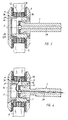
- the point holder shown in Figure 1 consists essentially of an axially symmetrical housing part 1 with a first external thread 1 a and a second external thread 1 b , to which a first holding part 2 in the form of a cap nut or a second holding part 3 are screwed in the form of a flange.
- the holding part 2 is inserted in a flange 4.
- the housing part 1 with the holding part 2 passes through the hole 5 a of a laminated safety glass plate 5, wherein the rings 3 and 4 engage over the bore 5 a and clamp the glass plate 5 with the interposition of Elastomerringthroughn 6.
- a joint according to DE 101 14 372 C2 is housed.
- the hinge pin 7 consists of a shaft 8 and an integrally formed on the front end head 9 with a spherical zone surface 9 a .
- a bearing ring 10 is screwed, which has in its front region a hollow spherical-zone-shaped bearing surface 10 a and in its rear region a frusto-conical opening 10 b .
- a suspension element 11 is inserted, so that the ball-zone-shaped surface 9 a of the head 9 is pressed against the bearing surface 10 a of the bearing ring 10 and guided on this.
- the component referred to here as a suspension element 11 may be a rubber-elastic annular or plate-shaped body, a coil spring or at least one disc spring or another member 9 pressing the head against the bearing surface 10 a .
- a form-fitting ring 12 On the integrally formed on the first holding part 2 threaded connector 2 a sits a form-fitting ring 12, which is shown in Figure 2 in perspective and enlarged.
- the ring 12 has on its outside evenly distributed over the circumference lamp sockets 12 a , are used in the lamps 13 in the form of light emitting diodes. Certainly noirhat the ring 12 an annular groove 12 b , are laid in the two ring cables 14 to which the lamp sockets 12 a are connected.
- the threaded connector 2 a of the holding part 2 has a radial slot 2 b , which is cut in Figure 1 and therefore not dashed.
- Two lines 15 lead from the ring cables 14 through the slot 2 b and an axial bore 7 a of the bolt 7 to a power source (not shown).
- a glass protective ring 16 made of hard plastic, which transmits the weight of the glass plate 5 and protects the ring 12 from pressure.
- the embodiment shown in Figure 3 differs from that of Figure 1, that the threaded connector 2 a of the holding part 2 is shortened and the first external thread 1 b of the housing part 1 is therefore moved further outwards.
- the lamps 13 containing the ring 12 is positively seated on the housing part 1 and has approximately the same distance from the two rings 3 and 4.
- the housing part 1 has an outgoing from the outer end face radial slot 1 e , through which the cable 15 (not shown) in the bore 7 a and on to the power source can be performed.
- the ring 12 is here flanked on both sides by a respective glass protection ring 16, which keep the glass plate 5 of the lamp ring 12 at a distance.
- the embodiment of Figure 4 differs from that of Figure 3 in that the first holding part 2 is not formed as a cap nut, but as a screw body with external thread 2 c .
- the housing part 1 is in turn provided with a radial slot 1 e , through which the cables 15 are guided in the pin bore 7 a and on to the power source.
- the lamp sockets 12 a with the lamps 13 and the inner annular groove 12 b are integrated into the housing part 1.
- the lamps are evenly distributed over the circumference of the lateral surface.
- the ring lines 14 (not shown) are laid in the annular groove 12 b , and the cable 15 (not shown) are led by Ltg. 14 directly into the bore 7 a of the bolt 7 and from there to the power source.
- a two spaced-held glass protection rings 16 are provided, which are flatter, however, because the height adjustment to the lamp ring 12 is omitted.
- the two rings 16 are held at at least two circumferential locations at a distance (not shown), so that the light radiation into the glass plate 5 by a displacement of the rings 16 can not be affected.
- the mounting of the glass plate is with point holders of this embodiment simplified, since the application of the lamp ring 12 is omitted and the Wiring is no longer done on site.
- each lamp holder 12 a inwardly to the annular groove 12 b leading holes for the connection of each socket 12 a to the loop 14 (not shown) included. It is also possible to lead the lines of all lamp holders 12 a without using ring lines 14 through the cable channel 7 a .
- the embodiment of the point holder shown in FIG. 6 largely corresponds to the holder shown in FIG.
- the same reference numerals denote the same parts in both figures; Reference is made in this regard to the description of FIG. Notwithstanding Figure 1, the housing part 1 has a smaller axial length, and accordingly the threaded connector 4 a longer than the threaded connector 2 a in Figure 1.
- the lamp ring 12 is therefore positioned substantially outside the axial region of the housing part 1.
- the flange 4 has an internal thread 4 b , in which a threaded cover 17 is screwed.
- the cable 15 is connected by the plug 18 with the coming of the ring cable 14 cables.
- the point holder light according to the invention is suitable i.a. for the Mounting of glass plates in stair railings and allows a stage near Illumination of the stairs.
Landscapes
- Civil Engineering (AREA)
- Structural Engineering (AREA)
- Engineering & Computer Science (AREA)
- Lighting Device Outwards From Vehicle And Optical Signal (AREA)
- Non-Portable Lighting Devices Or Systems Thereof (AREA)
- Materials For Medical Uses (AREA)
- Pivots And Pivotal Connections (AREA)
- Adhesive Tapes (AREA)
- Fastening Of Light Sources Or Lamp Holders (AREA)
- Common Detailed Techniques For Electron Tubes Or Discharge Tubes (AREA)
- Gripping Jigs, Holding Jigs, And Positioning Jigs (AREA)
- Clamps And Clips (AREA)
- Slide Fasteners, Snap Fasteners, And Hook Fasteners (AREA)
- Orthopedics, Nursing, And Contraception (AREA)
Abstract
Description
- 1
- Gehäuseteil
- 1a
- erstes Außengewinde
- 1b
- zweites Außengewinde
- 1c
- Innengewinde
- 1d
- Innenbund
- 1e
- Ausnehmung
- 2
- erstes Halteteil
- 2a
- Gewindestutzen
- 2b
- Ausnehmung
- 3
- zweites Halteteil
- 4
- Flanschring
- 4a
- Gewindestutzen
- 4b
- Innengewinde
- 5
- Glasplatte
- 5a
- Glasplattenbohrung
- 6
- Elastomerringscheibe
- 7
- Bolzen
- 7a
- Bolzenbohrung
- 8
- Schaft
- 9
- Kopf
- 9a
- Kugelzonenfläche
- 9b
- ebene Kopffläche
- 10
- Lagerring
- 10a
- hohlkugelzonenförmige Lagerfläche
- 10b
- Öffnung
- 11
- Federungselement
- 12
- Ring
- 12a
- Lampenfassung
- 12b
- Ringnut
- 13
- Lampe
- 14
- Ringkabel
- 15
- Leitungen
- 16
- Glasschutzring
- 17
- Gewindedeckel
- 18
- Stecker
Claims (11)
- Punkthalter für eine mit Bohrungen versehene Glasplatte (5) mit einem wenigstens teilweise in einer Glasplattenbohrung (5a) angeordneten Gehäuseteil (1), einem an dem Gehäuseteil (1) angeschraubten, den vorderen Rand der Glasplattenbohrung (5a) übergreifenden ersten Halteteil (2,4), einem den hinteren Rand der Glasplattenbohrung (5a) übergreitenden zweiten Halteteil (3) und einem an dem Gehäuseteil (1) angebrachten Bolzen (7),
dadurch gekennzeichnet, daß in dem Gehäuseteil (1) oder in einem das Gehäuseteil (1) umgebenden Ring (12) mehrere in die Glasplatte (5) gerichtete Lampen (13) angebracht sind,
der Bolzen (7) einen in seiner Längsrichtung verlaufenden Kabelkanal (7a) enthält, und
bei der Ausführung mit Ring (12) in dem Gehäuseteil (1) oder dem ersten Halteteil (2,2a) wenigstens eine Ausnehmung (1e bzw. 2b) für die Kabeldurchführung vorgesehen ist. - Punkthalter nach Anspruch 1, dadurch gekennzeichnet, daß der Ring (12) bzw. das Gehäuseteil (1) mehrere radial ausgerichtete Lampenfassungen (12a) aufweist.
- Punkthalter nach Anspruch 1 oder 2, dadurch gekennzeichnet, daß in dem Ring (12) bzw. dem Gehäuseteil (1) eine ringförmige Ausnehmung (12b) zur Aufnahme wenigstens eine Stromkabels (14) ausgebildet ist.
- Punkthalter nach einem der Ansprüche 1 bis 3, dadurch gekennzeichnet, daß die Lampen (13) Leuchtdioden sind.
- Punkthalter nach einem der Ansprüche 1 bis 4, dadurch gekennzeichnet, daß das erste Halteteil (2) als eine auf das Gehäuseteil (1) aufschraubbare Hutmutter ausgebildet ist.
- Punkthalter nach Anspruch 5, dadurch gekennzeichnet, daß der Ring (12) auf dem Gewindestutzen (2a) der Hutmutter aufsitzt und die Ausnehmung (2b) in dem Gewindestutzen (2a) der Hutmutter ausgebildet ist.
- Punkthalter nach einem der Ansprüche 1 bis 4, dadurch gekennzeichnet, daß das erste Halteteil (2) ein in das Gehäuseteil (1) einschraubbarer Körper mit Außengewinde (2c) ist.
- Punkthalter nach Anspruch 5 oder Anspruch 7, dadurch gekennzeichnet, daß der Ring (12) auf dem Gehäuseteil (1) aufsitzt und die Ausnehmung (1e) in dem Gehäuseteil (1) ausgebildet ist.
- Punkthalter nach einem der Ansprüche 6 bis 8, dadurch gekennzeichnet, daß die Ausnehmung (2b,1e) ein Schlitz in dem Gewindestutzen (2a) bzw. dem Gehäuseteil (1) ist.
- Punkthalter nach einem der Ansprüche 1 bis 9, dadurch gekennzeichnet, daß der Ring (12) bzw. der Lampenkranz in dem Gehäuseteil (1) einoder beidseitig von einem Glasschutzring (16) flankiert ist.
- Punkthalter nach einem der Ansprüche 1 bis 10, dadurch gekennzeichnet, daß der Bolzen (7) in dem Gehäuseteil (1) gelenkig gelagert ist.
Priority Applications (1)
| Application Number | Priority Date | Filing Date | Title |
|---|---|---|---|
| PL04016175T PL1503026T3 (pl) | 2003-07-28 | 2004-07-09 | Urządzenie do mocowania punktowego |
Applications Claiming Priority (2)
| Application Number | Priority Date | Filing Date | Title |
|---|---|---|---|
| DE10334227 | 2003-07-28 | ||
| DE10334227A DE10334227B3 (de) | 2003-07-28 | 2003-07-28 | Punkthalter |
Publications (3)
| Publication Number | Publication Date |
|---|---|
| EP1503026A2 true EP1503026A2 (de) | 2005-02-02 |
| EP1503026A3 EP1503026A3 (de) | 2005-12-07 |
| EP1503026B1 EP1503026B1 (de) | 2008-08-27 |
Family
ID=33521426
Family Applications (1)
| Application Number | Title | Priority Date | Filing Date |
|---|---|---|---|
| EP04016175A Expired - Lifetime EP1503026B1 (de) | 2003-07-28 | 2004-07-09 | Punkthalter |
Country Status (6)
| Country | Link |
|---|---|
| EP (1) | EP1503026B1 (de) |
| AT (1) | ATE406499T1 (de) |
| DE (2) | DE10334227B3 (de) |
| DK (1) | DK1503026T3 (de) |
| ES (1) | ES2312886T3 (de) |
| PL (1) | PL1503026T3 (de) |
Cited By (9)
| Publication number | Priority date | Publication date | Assignee | Title |
|---|---|---|---|---|
| EP1970966A3 (de) * | 2007-03-12 | 2011-03-30 | Webasto AG | Elektrisches Verbindungselement für Solarzellen |
| CN105178478A (zh) * | 2015-05-25 | 2015-12-23 | 深圳市三鑫幕墙工程有限公司 | 索结构驳接头调节装置 |
| EP2951500A4 (de) * | 2013-01-30 | 2016-11-16 | Cree Inc | Vereinfachtes flaches modul mit lichtleiter für hängende, oberflächenmontierte, wandhalterung und eigenständige leuchten |
| CN107119833A (zh) * | 2017-07-13 | 2017-09-01 | 谊美吉斯光电科技(福建)有限公司 | 一种led光电玻璃的框架系统 |
| RU184775U1 (ru) * | 2018-07-05 | 2018-11-08 | Ашот Беджанович Оганесян | Стеклодержатель |
| WO2018202226A1 (de) * | 2017-05-05 | 2018-11-08 | Mts Produkte Für Den Schwimmbadbau Und Die Unterwassertechnik Gmbh | Anordnung zur befestigung eines scheinwerfers, insbesondere eines unterwasserscheinwerfers |
| US10234616B2 (en) | 2013-01-30 | 2019-03-19 | Cree, Inc. | Simplified low profile module with light guide for pendant, surface mount, wall mount and stand alone luminaires |
| US10895365B2 (en) | 2013-03-15 | 2021-01-19 | Ideal Industries Lighting Llc | Lighting apparatus with reflector and outer lens |
| US11099317B2 (en) | 2013-01-30 | 2021-08-24 | Ideal Industries Lighting Llc | Multi-stage optical waveguide for a luminaire |
Families Citing this family (3)
| Publication number | Priority date | Publication date | Assignee | Title |
|---|---|---|---|---|
| DE102007045950B3 (de) * | 2007-09-25 | 2009-05-20 | Insta Elektro Gmbh | Halter |
| DE102008051717A1 (de) | 2008-10-18 | 2010-04-22 | Kl Megla Gmbh | Vorrichtung zur Stromerzeugung |
| DE102010040310A1 (de) * | 2010-09-07 | 2011-11-03 | Siemens Aktiengesellschaft | Kabelverschraubung |
Citations (2)
| Publication number | Priority date | Publication date | Assignee | Title |
|---|---|---|---|---|
| DE10114372A1 (de) | 2001-03-23 | 2002-10-24 | Sws Glasbaubeschlaege Gmbh | Punkthalter |
| DE10122370C2 (de) | 2001-05-09 | 2003-06-12 | Sws Glasbaubeschlaege Gmbh | Punkthalter |
Family Cites Families (5)
| Publication number | Priority date | Publication date | Assignee | Title |
|---|---|---|---|---|
| DE8909067U1 (de) * | 1989-07-26 | 1989-11-30 | Autronic Gmbh, 7500 Karlsruhe | Lichtleiste für einen Regaleinsatz |
| EP1025329B1 (de) * | 1998-06-04 | 2004-03-03 | DORMA GmbH + Co. KG | Befestigungsvorrichtung für eine glasplatte an einer gebäudeseitigen halterung |
| EP1035369B1 (de) * | 1999-03-08 | 2004-09-29 | Wilfried Pöllet | Beleuchtungsanordung |
| DE10052529A1 (de) * | 2000-10-23 | 2002-05-16 | Dorma Gmbh & Co Kg | Solarmodul |
| DE20304038U1 (de) * | 2003-03-13 | 2003-06-12 | Solingglas Bau und Veredelungs GmbH & Co. KG, 37691 Derental | Hinterleuchtete Glas-Treppenstufe |
-
2003
- 2003-07-28 DE DE10334227A patent/DE10334227B3/de not_active Expired - Fee Related
-
2004
- 2004-07-09 EP EP04016175A patent/EP1503026B1/de not_active Expired - Lifetime
- 2004-07-09 ES ES04016175T patent/ES2312886T3/es not_active Expired - Lifetime
- 2004-07-09 DK DK04016175T patent/DK1503026T3/da active
- 2004-07-09 PL PL04016175T patent/PL1503026T3/pl unknown
- 2004-07-09 AT AT04016175T patent/ATE406499T1/de active
- 2004-07-09 DE DE502004007937T patent/DE502004007937D1/de not_active Expired - Lifetime
Patent Citations (2)
| Publication number | Priority date | Publication date | Assignee | Title |
|---|---|---|---|---|
| DE10114372A1 (de) | 2001-03-23 | 2002-10-24 | Sws Glasbaubeschlaege Gmbh | Punkthalter |
| DE10122370C2 (de) | 2001-05-09 | 2003-06-12 | Sws Glasbaubeschlaege Gmbh | Punkthalter |
Cited By (12)
| Publication number | Priority date | Publication date | Assignee | Title |
|---|---|---|---|---|
| EP1970966A3 (de) * | 2007-03-12 | 2011-03-30 | Webasto AG | Elektrisches Verbindungselement für Solarzellen |
| EP2951500A4 (de) * | 2013-01-30 | 2016-11-16 | Cree Inc | Vereinfachtes flaches modul mit lichtleiter für hängende, oberflächenmontierte, wandhalterung und eigenständige leuchten |
| US10234616B2 (en) | 2013-01-30 | 2019-03-19 | Cree, Inc. | Simplified low profile module with light guide for pendant, surface mount, wall mount and stand alone luminaires |
| US11070493B2 (en) | 2013-01-30 | 2021-07-20 | Ideal Industries Lighting Llc | Simplified low profile module with light guide for pendant, surface mount, wall mount and stand alone luminaires |
| US11099317B2 (en) | 2013-01-30 | 2021-08-24 | Ideal Industries Lighting Llc | Multi-stage optical waveguide for a luminaire |
| US11675120B2 (en) | 2013-01-30 | 2023-06-13 | Ideal Industries Lighting Llc | Optical waveguides for light fixtures and luminaires |
| US10895365B2 (en) | 2013-03-15 | 2021-01-19 | Ideal Industries Lighting Llc | Lighting apparatus with reflector and outer lens |
| CN105178478A (zh) * | 2015-05-25 | 2015-12-23 | 深圳市三鑫幕墙工程有限公司 | 索结构驳接头调节装置 |
| CN105178478B (zh) * | 2015-05-25 | 2018-01-26 | 深圳市三鑫科技发展有限公司 | 索结构驳接头调节装置 |
| WO2018202226A1 (de) * | 2017-05-05 | 2018-11-08 | Mts Produkte Für Den Schwimmbadbau Und Die Unterwassertechnik Gmbh | Anordnung zur befestigung eines scheinwerfers, insbesondere eines unterwasserscheinwerfers |
| CN107119833A (zh) * | 2017-07-13 | 2017-09-01 | 谊美吉斯光电科技(福建)有限公司 | 一种led光电玻璃的框架系统 |
| RU184775U1 (ru) * | 2018-07-05 | 2018-11-08 | Ашот Беджанович Оганесян | Стеклодержатель |
Also Published As
| Publication number | Publication date |
|---|---|
| ATE406499T1 (de) | 2008-09-15 |
| EP1503026B1 (de) | 2008-08-27 |
| EP1503026A3 (de) | 2005-12-07 |
| DE10334227B3 (de) | 2005-02-24 |
| PL1503026T3 (pl) | 2009-02-27 |
| DE502004007937D1 (de) | 2008-10-09 |
| ES2312886T3 (es) | 2009-03-01 |
| DK1503026T3 (da) | 2009-01-05 |
Similar Documents
| Publication | Publication Date | Title |
|---|---|---|
| EP1503026B1 (de) | Punkthalter | |
| DE9202608U1 (de) | Anzeigeelement | |
| EP0446875A2 (de) | Schutzgehäuse fÀ¼r optische Geräte | |
| DE29906234U1 (de) | Universalarbeitslampe | |
| DE102009030282B4 (de) | Lichterkette | |
| DE60004333T2 (de) | Elektrischer verbinder mit schneidklemmschraube | |
| EP3527873A1 (de) | Set zur realisierung eines einbaustrahlers | |
| DE10322177A1 (de) | LED-Einbauleuchte | |
| DE102013108157A1 (de) | Pendelleuchte mit einem LED-Leuchtmittel | |
| DE19736006A1 (de) | Gelenkverbindung für Leuchtensystem | |
| DE20305625U1 (de) | Laterne zum Rundumabstrahlen eines Warnsignals | |
| DD263105A1 (de) | Spritzwassergeschuetzte strahlerleuchte | |
| EP3276250A1 (de) | Rotierbare leuchte und drehvorrichtung | |
| EP0649196B1 (de) | Niedervoltinstallationssystem | |
| DE10149258A1 (de) | Gehäuse für ein Unterflurfeuer | |
| DE202019106323U1 (de) | Anpassbare Träger für Leuchten in Nischen | |
| DE102014106229A1 (de) | Leuchtenstele | |
| DE10338885A1 (de) | Beleuchtungseinrichtung für einen Nassbereich und Verfahren zu ihrer Herstellung | |
| DE20010707U1 (de) | Leuchte | |
| DE29815368U1 (de) | Niedervolt-Deckeneinbauleuchte | |
| DE102024104522A1 (de) | Anordnungselement für LED und lichtlenkendes Bauelement | |
| EP0139075A1 (de) | Scheinwerfereinheit | |
| WO2009052939A1 (de) | Hallenreflektorleuchte | |
| DE102024004481A1 (de) | Anordnungselement für LED und lichtlenkendes Bauelement | |
| DE4430200C2 (de) | Einbauelement zur Aufnahme und Befestigung eines Unterwasserscheinwerfers |
Legal Events
| Date | Code | Title | Description |
|---|---|---|---|
| PUAI | Public reference made under article 153(3) epc to a published international application that has entered the european phase |
Free format text: ORIGINAL CODE: 0009012 |
|
| AK | Designated contracting states |
Kind code of ref document: A2 Designated state(s): AT BE BG CH CY CZ DE DK EE ES FI FR GB GR HU IE IT LI LU MC NL PL PT RO SE SI SK TR |
|
| AX | Request for extension of the european patent |
Extension state: AL HR LT LV MK |
|
| PUAL | Search report despatched |
Free format text: ORIGINAL CODE: 0009013 |
|
| AK | Designated contracting states |
Kind code of ref document: A3 Designated state(s): AT BE BG CH CY CZ DE DK EE ES FI FR GB GR HU IE IT LI LU MC NL PL PT RO SE SI SK TR |
|
| AX | Request for extension of the european patent |
Extension state: AL HR LT LV MK |
|
| AKX | Designation fees paid |
Designated state(s): AT BE BG CH CY CZ DE DK EE ES FI FR GB GR HU IE IT LI LU MC NL PL PT RO SE SI SK TR |
|
| 17P | Request for examination filed |
Effective date: 20060616 |
|
| GRAP | Despatch of communication of intention to grant a patent |
Free format text: ORIGINAL CODE: EPIDOSNIGR1 |
|
| GRAS | Grant fee paid |
Free format text: ORIGINAL CODE: EPIDOSNIGR3 |
|
| GRAA | (expected) grant |
Free format text: ORIGINAL CODE: 0009210 |
|
| AK | Designated contracting states |
Kind code of ref document: B1 Designated state(s): AT BE BG CH CY CZ DE DK EE ES FI FR GB GR HU IE IT LI LU MC NL PL PT RO SE SI SK TR |
|
| REG | Reference to a national code |
Ref country code: GB Ref legal event code: FG4D Free format text: NOT ENGLISH |
|
| REG | Reference to a national code |
Ref country code: CH Ref legal event code: EP |
|
| REG | Reference to a national code |
Ref country code: IE Ref legal event code: FG4D Free format text: LANGUAGE OF EP DOCUMENT: GERMAN |
|
| REF | Corresponds to: |
Ref document number: 502004007937 Country of ref document: DE Date of ref document: 20081009 Kind code of ref document: P |
|
| REG | Reference to a national code |
Ref country code: CH Ref legal event code: NV Representative=s name: KATZAROV S.A. |
|
| REG | Reference to a national code |
Ref country code: SE Ref legal event code: TRGR |
|
| REG | Reference to a national code |
Ref country code: DK Ref legal event code: T3 |
|
| PG25 | Lapsed in a contracting state [announced via postgrant information from national office to epo] |
Ref country code: SI Free format text: LAPSE BECAUSE OF FAILURE TO SUBMIT A TRANSLATION OF THE DESCRIPTION OR TO PAY THE FEE WITHIN THE PRESCRIBED TIME-LIMIT Effective date: 20080827 |
|
| REG | Reference to a national code |
Ref country code: PL Ref legal event code: T3 |
|
| REG | Reference to a national code |
Ref country code: ES Ref legal event code: FG2A Ref document number: 2312886 Country of ref document: ES Kind code of ref document: T3 |
|
| PG25 | Lapsed in a contracting state [announced via postgrant information from national office to epo] |
Ref country code: BG Free format text: LAPSE BECAUSE OF FAILURE TO SUBMIT A TRANSLATION OF THE DESCRIPTION OR TO PAY THE FEE WITHIN THE PRESCRIBED TIME-LIMIT Effective date: 20081127 |
|
| PG25 | Lapsed in a contracting state [announced via postgrant information from national office to epo] |
Ref country code: RO Free format text: LAPSE BECAUSE OF FAILURE TO SUBMIT A TRANSLATION OF THE DESCRIPTION OR TO PAY THE FEE WITHIN THE PRESCRIBED TIME-LIMIT Effective date: 20080827 Ref country code: SK Free format text: LAPSE BECAUSE OF FAILURE TO SUBMIT A TRANSLATION OF THE DESCRIPTION OR TO PAY THE FEE WITHIN THE PRESCRIBED TIME-LIMIT Effective date: 20080827 Ref country code: PT Free format text: LAPSE BECAUSE OF FAILURE TO SUBMIT A TRANSLATION OF THE DESCRIPTION OR TO PAY THE FEE WITHIN THE PRESCRIBED TIME-LIMIT Effective date: 20090127 |
|
| PLBE | No opposition filed within time limit |
Free format text: ORIGINAL CODE: 0009261 |
|
| STAA | Information on the status of an ep patent application or granted ep patent |
Free format text: STATUS: NO OPPOSITION FILED WITHIN TIME LIMIT |
|
| PG25 | Lapsed in a contracting state [announced via postgrant information from national office to epo] |
Ref country code: EE Free format text: LAPSE BECAUSE OF FAILURE TO SUBMIT A TRANSLATION OF THE DESCRIPTION OR TO PAY THE FEE WITHIN THE PRESCRIBED TIME-LIMIT Effective date: 20080827 |
|
| 26N | No opposition filed |
Effective date: 20090528 |
|
| PG25 | Lapsed in a contracting state [announced via postgrant information from national office to epo] |
Ref country code: MC Free format text: LAPSE BECAUSE OF NON-PAYMENT OF DUE FEES Effective date: 20090731 |
|
| PG25 | Lapsed in a contracting state [announced via postgrant information from national office to epo] |
Ref country code: GR Free format text: LAPSE BECAUSE OF FAILURE TO SUBMIT A TRANSLATION OF THE DESCRIPTION OR TO PAY THE FEE WITHIN THE PRESCRIBED TIME-LIMIT Effective date: 20081128 |
|
| PG25 | Lapsed in a contracting state [announced via postgrant information from national office to epo] |
Ref country code: LU Free format text: LAPSE BECAUSE OF NON-PAYMENT OF DUE FEES Effective date: 20090709 |
|
| PG25 | Lapsed in a contracting state [announced via postgrant information from national office to epo] |
Ref country code: HU Free format text: LAPSE BECAUSE OF FAILURE TO SUBMIT A TRANSLATION OF THE DESCRIPTION OR TO PAY THE FEE WITHIN THE PRESCRIBED TIME-LIMIT Effective date: 20090228 |
|
| PG25 | Lapsed in a contracting state [announced via postgrant information from national office to epo] |
Ref country code: CY Free format text: LAPSE BECAUSE OF FAILURE TO SUBMIT A TRANSLATION OF THE DESCRIPTION OR TO PAY THE FEE WITHIN THE PRESCRIBED TIME-LIMIT Effective date: 20080827 |
|
| PGFP | Annual fee paid to national office [announced via postgrant information from national office to epo] |
Ref country code: CH Payment date: 20110725 Year of fee payment: 8 Ref country code: DK Payment date: 20110725 Year of fee payment: 8 |
|
| PGFP | Annual fee paid to national office [announced via postgrant information from national office to epo] |
Ref country code: CZ Payment date: 20120628 Year of fee payment: 9 Ref country code: TR Payment date: 20120629 Year of fee payment: 9 |
|
| PGFP | Annual fee paid to national office [announced via postgrant information from national office to epo] |
Ref country code: PL Payment date: 20120614 Year of fee payment: 9 |
|
| PGFP | Annual fee paid to national office [announced via postgrant information from national office to epo] |
Ref country code: IE Payment date: 20120720 Year of fee payment: 9 Ref country code: GB Payment date: 20120723 Year of fee payment: 9 Ref country code: FI Payment date: 20120720 Year of fee payment: 9 Ref country code: SE Payment date: 20120723 Year of fee payment: 9 |
|
| PGFP | Annual fee paid to national office [announced via postgrant information from national office to epo] |
Ref country code: FR Payment date: 20120803 Year of fee payment: 9 Ref country code: DE Payment date: 20120924 Year of fee payment: 9 Ref country code: ES Payment date: 20120723 Year of fee payment: 9 Ref country code: IT Payment date: 20120725 Year of fee payment: 9 Ref country code: BE Payment date: 20120724 Year of fee payment: 9 |
|
| PGFP | Annual fee paid to national office [announced via postgrant information from national office to epo] |
Ref country code: NL Payment date: 20120718 Year of fee payment: 9 |
|
| PGFP | Annual fee paid to national office [announced via postgrant information from national office to epo] |
Ref country code: AT Payment date: 20120720 Year of fee payment: 9 |
|
| BERE | Be: lapsed |
Owner name: SWS G.- FUR GLASBAUBESCHLAGE MBH Effective date: 20130731 |
|
| REG | Reference to a national code |
Ref country code: NL Ref legal event code: V1 Effective date: 20140201 |
|
| REG | Reference to a national code |
Ref country code: DK Ref legal event code: EBP Effective date: 20130731 |
|
| REG | Reference to a national code |
Ref country code: CH Ref legal event code: PL |
|
| REG | Reference to a national code |
Ref country code: SE Ref legal event code: EUG |
|
| REG | Reference to a national code |
Ref country code: AT Ref legal event code: MM01 Ref document number: 406499 Country of ref document: AT Kind code of ref document: T Effective date: 20130709 |
|
| GBPC | Gb: european patent ceased through non-payment of renewal fee |
Effective date: 20130709 |
|
| REG | Reference to a national code |
Ref country code: IE Ref legal event code: MM4A |
|
| REG | Reference to a national code |
Ref country code: FR Ref legal event code: ST Effective date: 20140331 |
|
| PG25 | Lapsed in a contracting state [announced via postgrant information from national office to epo] |
Ref country code: LI Free format text: LAPSE BECAUSE OF NON-PAYMENT OF DUE FEES Effective date: 20130731 Ref country code: BE Free format text: LAPSE BECAUSE OF NON-PAYMENT OF DUE FEES Effective date: 20130731 Ref country code: CH Free format text: LAPSE BECAUSE OF NON-PAYMENT OF DUE FEES Effective date: 20130731 Ref country code: CZ Free format text: LAPSE BECAUSE OF NON-PAYMENT OF DUE FEES Effective date: 20130709 Ref country code: FI Free format text: LAPSE BECAUSE OF NON-PAYMENT OF DUE FEES Effective date: 20130709 Ref country code: DE Free format text: LAPSE BECAUSE OF NON-PAYMENT OF DUE FEES Effective date: 20140201 Ref country code: NL Free format text: LAPSE BECAUSE OF NON-PAYMENT OF DUE FEES Effective date: 20140201 Ref country code: SE Free format text: LAPSE BECAUSE OF NON-PAYMENT OF DUE FEES Effective date: 20130710 Ref country code: GB Free format text: LAPSE BECAUSE OF NON-PAYMENT OF DUE FEES Effective date: 20130709 |
|
| REG | Reference to a national code |
Ref country code: DE Ref legal event code: R119 Ref document number: 502004007937 Country of ref document: DE Effective date: 20140201 |
|
| PG25 | Lapsed in a contracting state [announced via postgrant information from national office to epo] |
Ref country code: FR Free format text: LAPSE BECAUSE OF NON-PAYMENT OF DUE FEES Effective date: 20130731 Ref country code: AT Free format text: LAPSE BECAUSE OF NON-PAYMENT OF DUE FEES Effective date: 20130709 Ref country code: IT Free format text: LAPSE BECAUSE OF NON-PAYMENT OF DUE FEES Effective date: 20130709 |
|
| PG25 | Lapsed in a contracting state [announced via postgrant information from national office to epo] |
Ref country code: IE Free format text: LAPSE BECAUSE OF NON-PAYMENT OF DUE FEES Effective date: 20130709 |
|
| PG25 | Lapsed in a contracting state [announced via postgrant information from national office to epo] |
Ref country code: DK Free format text: LAPSE BECAUSE OF NON-PAYMENT OF DUE FEES Effective date: 20130731 |
|
| REG | Reference to a national code |
Ref country code: PL Ref legal event code: LAPE |
|
| PG25 | Lapsed in a contracting state [announced via postgrant information from national office to epo] |
Ref country code: PL Free format text: LAPSE BECAUSE OF NON-PAYMENT OF DUE FEES Effective date: 20130709 |
|
| REG | Reference to a national code |
Ref country code: ES Ref legal event code: FD2A Effective date: 20150331 |
|
| PG25 | Lapsed in a contracting state [announced via postgrant information from national office to epo] |
Ref country code: ES Free format text: LAPSE BECAUSE OF NON-PAYMENT OF DUE FEES Effective date: 20130710 |
|
| PG25 | Lapsed in a contracting state [announced via postgrant information from national office to epo] |
Ref country code: TR Free format text: LAPSE BECAUSE OF NON-PAYMENT OF DUE FEES Effective date: 20130709 |