EP1501995B1 - Lasche - Google Patents
Lasche Download PDFInfo
- Publication number
- EP1501995B1 EP1501995B1 EP03725094A EP03725094A EP1501995B1 EP 1501995 B1 EP1501995 B1 EP 1501995B1 EP 03725094 A EP03725094 A EP 03725094A EP 03725094 A EP03725094 A EP 03725094A EP 1501995 B1 EP1501995 B1 EP 1501995B1
- Authority
- EP
- European Patent Office
- Prior art keywords
- bracket
- tab
- end portions
- bracket according
- rail
- Prior art date
- Legal status (The legal status is an assumption and is not a legal conclusion. Google has not performed a legal analysis and makes no representation as to the accuracy of the status listed.)
- Expired - Lifetime
Links
- 239000000725 suspension Substances 0.000 title 1
- 239000000463 material Substances 0.000 description 7
- 238000004519 manufacturing process Methods 0.000 description 4
- 230000007704 transition Effects 0.000 description 2
- 241001417935 Platycephalidae Species 0.000 description 1
- 208000027418 Wounds and injury Diseases 0.000 description 1
- 238000005266 casting Methods 0.000 description 1
- 238000004140 cleaning Methods 0.000 description 1
- 238000010276 construction Methods 0.000 description 1
- 238000011109 contamination Methods 0.000 description 1
- 230000006378 damage Effects 0.000 description 1
- 230000001419 dependent effect Effects 0.000 description 1
- 239000011521 glass Substances 0.000 description 1
- 230000002401 inhibitory effect Effects 0.000 description 1
- 208000014674 injury Diseases 0.000 description 1
- 238000009434 installation Methods 0.000 description 1
- 239000002184 metal Substances 0.000 description 1
- 239000007769 metal material Substances 0.000 description 1
- 238000012986 modification Methods 0.000 description 1
- 230000004048 modification Effects 0.000 description 1
- 230000003287 optical effect Effects 0.000 description 1
- 238000005457 optimization Methods 0.000 description 1
- 229920003023 plastic Polymers 0.000 description 1
- 239000004033 plastic Substances 0.000 description 1
- 238000010408 sweeping Methods 0.000 description 1
Images


Classifications
-
- E—FIXED CONSTRUCTIONS
- E05—LOCKS; KEYS; WINDOW OR DOOR FITTINGS; SAFES
- E05D—HINGES OR SUSPENSION DEVICES FOR DOORS, WINDOWS OR WINGS
- E05D15/00—Suspension arrangements for wings
- E05D15/06—Suspension arrangements for wings for wings sliding horizontally more or less in their own plane
- E05D15/0621—Details, e.g. suspension or supporting guides
- E05D15/0626—Details, e.g. suspension or supporting guides for wings suspended at the top
- E05D15/063—Details, e.g. suspension or supporting guides for wings suspended at the top on wheels with fixed axis
-
- E—FIXED CONSTRUCTIONS
- E05—LOCKS; KEYS; WINDOW OR DOOR FITTINGS; SAFES
- E05Y—INDEXING SCHEME ASSOCIATED WITH SUBCLASSES E05D AND E05F, RELATING TO CONSTRUCTION ELEMENTS, ELECTRIC CONTROL, POWER SUPPLY, POWER SIGNAL OR TRANSMISSION, USER INTERFACES, MOUNTING OR COUPLING, DETAILS, ACCESSORIES, AUXILIARY OPERATIONS NOT OTHERWISE PROVIDED FOR, APPLICATION THEREOF
- E05Y2201/00—Constructional elements; Accessories therefor
- E05Y2201/60—Suspension or transmission members; Accessories therefor
- E05Y2201/606—Accessories therefor
- E05Y2201/61—Cooperation between suspension or transmission members
- E05Y2201/612—Cooperation between suspension or transmission members between carriers and rails
- E05Y2201/614—Anti-derailing means
-
- E—FIXED CONSTRUCTIONS
- E05—LOCKS; KEYS; WINDOW OR DOOR FITTINGS; SAFES
- E05Y—INDEXING SCHEME ASSOCIATED WITH SUBCLASSES E05D AND E05F, RELATING TO CONSTRUCTION ELEMENTS, ELECTRIC CONTROL, POWER SUPPLY, POWER SIGNAL OR TRANSMISSION, USER INTERFACES, MOUNTING OR COUPLING, DETAILS, ACCESSORIES, AUXILIARY OPERATIONS NOT OTHERWISE PROVIDED FOR, APPLICATION THEREOF
- E05Y2800/00—Details, accessories and auxiliary operations not otherwise provided for
- E05Y2800/67—Materials; Strength alteration thereof
- E05Y2800/672—Glass
-
- E—FIXED CONSTRUCTIONS
- E05—LOCKS; KEYS; WINDOW OR DOOR FITTINGS; SAFES
- E05Y—INDEXING SCHEME ASSOCIATED WITH SUBCLASSES E05D AND E05F, RELATING TO CONSTRUCTION ELEMENTS, ELECTRIC CONTROL, POWER SUPPLY, POWER SIGNAL OR TRANSMISSION, USER INTERFACES, MOUNTING OR COUPLING, DETAILS, ACCESSORIES, AUXILIARY OPERATIONS NOT OTHERWISE PROVIDED FOR, APPLICATION THEREOF
- E05Y2900/00—Application of doors, windows, wings or fittings thereof
- E05Y2900/10—Application of doors, windows, wings or fittings thereof for buildings or parts thereof
- E05Y2900/13—Type of wing
- E05Y2900/132—Doors
Definitions
- the invention relates to a tab according to the preamble of claim 1.
- tabs elements can be slidably suspended and guided on a rail assembly. Most of the tab is guided over a supporting role at the top of a rail, which is attached to a substructure.
- US 1,606,450 shows a tab for attaching a glass sheet to a rail which has a transversal surface with a convex surface into which the flat heads of countersunk screws are embedded.
- a screw with a protruding from the tab screw head is attached to the game to the rail to be adjusted. This screw is laterally secured by a further screw against adjustment.
- the tab according to the invention it has been possible, by means of a particularly advantageous combination of the amount of material used and the shape design, to create a functional and at the same time visually appealing unit.
- a spherical surface and rounded end areas allow a small depth and a small longitudinal extent, so that a compact unit was created.
- the tab designed in this way allows optimal utilization of the installation space and an optimization of the manufacturing effort and the material used.
- the material requirement for the tab according to the invention is extremely low, the stability and functional properties are ensured.
- the resulting outer contours are made visually appealing by flowing transitions. All edges and edges are provided with radii. All material thicknesses are reduced to a minimum.
- the flowing course of the outer contours, in particular the front and edge surfaces, significantly reduces the use of materials and reduces casting manufacturing problems. Conceivable are both metallic materials, plastics or so-called hybrid materials.
- the color scheme is largely unlimited.
- the properties mentioned also contribute significantly to the reduction of manufacturing costs.
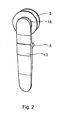
- the tab has a basically flat, elongated shape, wherein a center section spans between opposite end regions.
- the two end portions are semicircular.
- Of the Center section has a constant width, which initially continues in the two end regions and ends represents the diameter of the semicircles.
- the observer facing surface of the tab is not interrupted by functional elements.
- the surface is formed slightly convex both in the longitudinal direction between the end regions and between the lateral edges, wherein the surface of the surrounding edges rises slightly in the body slightly raised. Overall, a visually uniform and smooth surface is created.
- a lid is integrated flush in the surface, which covers the mounting area of a rear-mounted lift-off.
- a roller is fastened to a bearing body at the upper end region of the tab, which roller serves for displaceably guiding the tab on the rail.
- the bearing body is hidden by the rounded end for the viewer.
- the rear side in the center section arranged lift-off prevents unauthorized lifting the tab from the rail.
- the lift-out safety device is mounted on the rail after attaching the tab and fastened on the front.
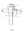
- a stopper can be mounted laterally on the tab, which ensures a quiet and gentle stopping of the element at a corresponding boundary.
- fasteners / openings are required on the back. In order to create an optically uniform surface, this area is closed by a cover. At the same time it prevents dirt from entering the area and impairing the functions.
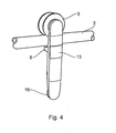
- FIGS. 1 to 6 a tab is designated in FIGS. 1 to 6, by means of which a non-illustrated element can be displaceably arranged on a rail 2.
- the tab 1 is guided over a supporting roller 3 at the top of the rail 2, which is attached to a substructure, not shown.
- point holders 4 by means of which the element is fastened, can be arranged on the lug 1.
- a lift-5 and / or a stopper 6 can be attached.
- the element may be a space-locking door or a locker door of a cabinet or shelf. It is also conceivable position-variable elements that represent separating functions both in rooms and in cabinets or shelves.
- the tab 1 has a basically flat, elongated shape, wherein integrally spans a central portion 9 between opposite end portions 7 and 8.
- the two end regions 7 and 8 protrude semicircular into the space.
- the middle section 9 has a constant width B, which is initially in the two end regions 7, 8 continues and ends the diameter D of the semicircular end portions 7, 8 represents.
- the observer facing surface 10 of the tab 1 is not interrupted by functional elements and is slightly convex, the surface 10 of the surrounding marginal edges 11 increases slightly in the body slightly raised.
- the transition between the end regions 7 and 8 and the center section 9 is in each case optically highlighted by a transverse groove 12.
- a cover 13 is flush with the surface 10 integrated. The cover 13 covers the attachment of the rear-mounted lifting lock 5 from.
- the roller 3 On the rear side facing away from the viewer 14, the roller 3 is attached to the upper end portion 7 of the tab 1, which serves for the sliding guide of the tab 1 on the rail 2.
- the bearing of the roller 3 takes place on a bearing body 15 connected to the bracket 1, which is circular in shape and has at most the same diameter D of the semicircular end portion 7.
- the bearing body 15 is arranged concealed by the end portion 7 for the viewer.
- the back two point holder 4 for attachment of the element to be slidably guided on the rail 2.
- the attachment of the point holder 4 takes place connected to the tab 1 lugs 16, which include corresponding fastening means and are circular.
- the diameter D of the lugs 16 corresponds at most to the width B of the tab 1 or at most the diameter D of the semicircular end region 8, so that the lugs 16 are concealed by the end region 8 for the viewer.
- the rear side in the middle section 9 arranged lift-out 5 prevents unauthorized lifting the tab 1 of the rail 2.
- the lift-5 is mounted after mounting the tab 1 on the rail 2 and fastened front.
- a stopper 6 can be mounted laterally on the tab 1, which ensures a quiet and gentle stopping of the element at a corresponding boundary. Both options require fasteners / openings on the back.
- a visually uniform surface create this area is closed by a cover 17. At the same time it prevents dirt from entering the area and impairing the functions.
Landscapes
- Engineering & Computer Science (AREA)
- Mechanical Engineering (AREA)
- Support Devices For Sliding Doors (AREA)
- Vehicle Body Suspensions (AREA)
- Transition And Organic Metals Composition Catalysts For Addition Polymerization (AREA)
- Input Circuits Of Receivers And Coupling Of Receivers And Audio Equipment (AREA)
- Mirrors, Picture Frames, Photograph Stands, And Related Fastening Devices (AREA)
- Hooks, Suction Cups, And Attachment By Adhesive Means (AREA)
- Supporting Of Heads In Record-Carrier Devices (AREA)
- Wire Bonding (AREA)
- Electrical Discharge Machining, Electrochemical Machining, And Combined Machining (AREA)
- Bearings For Parts Moving Linearly (AREA)
- Holders For Apparel And Elements Relating To Apparel (AREA)
- Moving Of Heads (AREA)
- Connection Of Plates (AREA)
- Purses, Travelling Bags, Baskets, Or Suitcases (AREA)
Description
- Die Erfindung betrifft eine Lasche gemäß dem Oberbegriff des Patentanspruches 1.
- Mit derartigen Laschen können Elemente verschiebbar an einer Schienenanordnung aufgehängt und geführt werden. Meist wird die Lasche über eine tragende Rolle an der Oberseite einer Schiene geführt, die an einer Unterkonstruktion befestigt ist.
- Aus der US 1,116,331 ist eine derartige Lasche bekannt. Zwischen der an einer Schiene geführten Rolle und der Befestigung des verschiebbaren Elementes ist zusätzlich eine verstellbare Aushebesicherung realisiert. Die ausladende und mehrteilige Gestaltung der Lasche erfordert eine aufwendige Fertigung und ist unter dem Aspekt eines ökonomischen Materialeinsatzes nicht optimal.
- Die US 1,606,450 zeigt eine Lasche zur Befestigung einer Glasscheibe an eine Schiene, die in Querrichtung eine ballige Oberfläche aufweist, in die die ebenen Köpfe von Senkkopfschrauben eingelassen sind. Im oberen Bereich der Lasche ist eine Schraube mit einem von der Lasche abstehenden Schraubenkopf angebracht, mit der das Spiel zur Schiene eingestellt werden soll. Diese Schraube wird seitlich durch eine weitere Schraube gegen Verstellung abgesichert.
- Es ist daher die Aufgabe der vorliegenden Erfindung, eine Lasche nach dem Oberbegriff des Patentanspruches 1 zu schaffen, die eine kornpakte und optisch ansprechende Einheit mit geringstmöglicher räumlicher Ausdehnung bildet, wobei die bisherige Anwendungsvielfalt und die unterschiedlichen Funktionen beibehalten werden.
- Gelöst wird diese Aufgabe durch die im Patentanspruch 1 angegebenen Merkmale. Vorteilhafte Ausgestaltungen des Gegenstandes des Patentanspruches 1 ergeben sich aus den Unteransprüchen.
- Bei der erfindungsgemäßen Lasche ist es gelungen, durch eine besonders vorteilhafte Kombination der eingesetzten Materialmenge und der Formgestaltung, eine funktionsfähige und gleichzeitig optisch ansprechende Einheit zu schaffen. Eine ballige Oberfläche und abgerundete Endbereiche ermöglichen eine geringe Bautiefe und eine geringe Längserstreckung, so dass eine kompakte Einheit geschaffen wurde. Die derartig gestaltete Lasche ermöglicht eine optimale Ausnutzung des Bauraumes und eine Optimierung des Fertigungsaufwandes und des eingesetzten Materials.
- Obwohl der Materialbedarf für die erfindungsgemäße Lasche äußerst gering ist, sind die Stabilitäts- und Funktionseigenschaften gewährleistet. Die sich ergebenden Außenkonturen werden durch fließende Übergänge optisch ansprechend gestaltet. Alle Kanten und Ränder sind mit Radien versehen. Alle Materialstärken sind auf ein Minimum reduziert. Der fließende Verlauf der Außenkonturen, insbesondere der Front- und Randflächen, reduziert den Materialeinsatz erheblich und vermindert gießtechnische Fertigungsprobleme. Denkbar sind sowohl metallische Materialien, Kunststoffe oder so genannte Hybridwerkstoffe. Die farbliche Gestaltung ist weitgehend unbeschränkt. Die genannten Eigenschaften tragen außerdem wesentlich zur Reduzierung der Herstellungskosten bei.
- Durch eine verdeckte Anordnung von Befestigungsansätzen/-bereichen für Laufrollen und Verbindungen zu einem zu tragenden Element oder weiteren Anbauteilen wird ein vorteilhaftes optisches Konzept geschaffen, das sich besonders gut in das klare und transparente Erscheinungsbild entmaterialisierter Glas-Metall-Konstruktionen einfügt. Die frontseitig und/ oder rückseitig angeordneten Befestigungsbereiche sind mittels Deckeln geschützt, so dass funktionshemmende Verschmutzungen vermieden werden. Die Lasche weist keine vorstehenden oder scharfkantigen Teile auf, so dass Reinigungsarbeiten erleichtert werden und diesbezügliche Verletzungsquellen eliminiert worden sind.
- Die Lasche weist eine prinzipiell flache, längliche Form auf, wobei sich zwischen gegenüberliegenden Endbereichen ein Mittenabschnitt aufspannt. Die beiden Endbereiche sind halbkreisförmig ausgebildet. Der Mittenabschnitt weist eine gleichbleibende Breite auf, die sich zunächst in den beiden Endbereichen fortsetzt und endseitig den Durchmesser der Halbkreise darstellt.
- Die dem Betrachter zugewandte Oberfläche der Lasche wird nicht durch Funktionselemente unterbrochen. Die Oberfläche ist sowohl in Längserstreckung zwischen den Endbereichen als auch zwischen den seitlichen Rändern leicht ballig ausgebildet, wobei die Oberfläche von den umgebenden Randkanten körpereinwärts leicht erhaben ansteigt. Insgesamt wird eine optisch einheitliche und glatte Fläche geschaffen. Im Mittenabschnitt ist ein Deckel bündig in die Oberfläche integriert, der den Befestigungsbereich einer rückseitig angeordneten Aushebesicherung verdeckt.
- Auf der dem Betrachter abgewandten Rückseite ist am oberen Endbereich der Lasche eine Rolle an einem Lagerkörper befestigt, die zur verschiebbaren Führung der Lasche an der Schiene dient. Der Lagerkörper ist durch den abgerundeten Endbereich für den Betrachter verdeckt angeordnet. Am unteren Endbereich befinden sich rückseitig zwei Punkthalter zur Befestigung des Elementes, das verschiebbar an der Schiene geführt werden soll. Die Befestigung der Punkthalter erfolgt an mit der Lasche verbundenen Ansätzen, die für den Betrachter ebenfalls verdeckt angeordnet sind.
- Die rückseitig im Mittenabschnitt angeordnete Aushebesicherung verhindert ein unberechtigtes Abheben der Lasche von der Schiene. Die Aushebesicherung wird nach Aufsetzen der Lasche auf die Schiene montiert und frontseitig befestigt. Des Weiteren kann seitlich an der Lasche ein Stopper montiert werden, der ein geräuscharmes und sanftes Stoppen des Elementes an einer entsprechenden Begrenzung gewährleistet. Für beide Funktionen werden rückseitig Befestigungsmittel/-öffnungen benötigt. Um auch hier eine optisch einheitliche Oberfläche zu schaffen, wird dieser Bereich von einer Abdeckung verschlossen. Gleichzeitig wird verhindert, dass Schmutz in den Bereich eindringt und die Funktionen beeinträchtigt werden.
- Weitere Einzelheiten der Erfindung ergeben sich aus nachfolgender Beschreibung bevorzugter Ausführungsbeispiele anhand der Zeichnungen.
- Es zeigen:
- Figur 1:
- Eine Frontansicht einer Lasche.
- Figur 2:
- Eine Frontansicht einer Lasche, an der eine Tragrolle montiert ist.
- Figur 3:
- Eine Ansicht einer Lasche, die einen Stopper aufweist und die mittels einer Tragrolle an einer Führungsschiene verschiebbar geführt ist.
- Figur 4:
- Eine Ansicht einer Lasche, die mittels einer Tragrolle an einer Führungsschiene verschiebbar geführt ist.
- Figur 5:
- Eine rückwärtige Ansicht der Lasche gemäß der Figur 4.
- Figur 6:
- Eine Seitenansicht der Lasche gemäß der Figur 2 ohne Tragrolle.
- Mit 1 ist in den Figuren 1 bis 6 eine Lasche bezeichnet, mittels der ein nicht dargestelltes Element verschiebbar an einer Schiene 2 angeordnet werden kann. Die Lasche 1 wird über eine tragende Rolle 3 an der Oberseite der Schiene 2 geführt, die an einer nicht näher dargestellten Unterkonstruktion befestigt ist. An der Lasche 1 sind des Weiteren Punkthalter 4 anordbar, mittels derer das Element befestigt wird. Zwischen der Rolle 3 und den Punkthaltern 4 ist optional eine Aushebesicherung 5 und/oder ein Stopper 6 anbringbar. Das Element kann eine raumverschließende Tür oder eine Verschlusstür eines Schrankes oder Regales sein. Denkbar sind auch positionsveränderliche Elemente, die trennende Funktionen sowohl in Räumen als auch in Schränken oder Regalen darstellen.
- Die Lasche 1 weist eine prinzipiell flache, längliche Form auf, wobei sich zwischen gegenüberliegenden Endbereichen 7 und 8 einstückig ein Mittenabschnitt 9 aufspannt. Die beiden Endbereiche 7 und 8 ragen halbkreisförmig ausgebildet in den Raum. Der Mittenabschnitt 9 weist eine gleichbleibende Breite B auf, die sich zunächst in den beiden Endbereichen 7, 8 fortsetzt und endseitig den Durchmesser D der halbkreisförmigen Endbereiche 7, 8 darstellt.
- Die dem Betrachter zugewandte Oberfläche 10 der Lasche 1 wird nicht durch Funktionselemente unterbrochen und ist leicht ballig ausgebildet, wobei die Oberfläche 10 von den umgebenden Randkanten 11 körpereinwärts leicht erhaben ansteigt. Der Übergang zwischen den Endbereichen 7 und 8 und dem Mittenabschnitt 9 ist jeweils durch eine quer verlaufende Nut 12 optisch hervorgehoben. Im Mittenabschnitt 9 ist ein Deckel 13 bündig in die Oberfläche 10 integriert. Der Deckel 13 deckt die Befestigung der rückseitig angeordneten Aushebesicherung 5 ab.
- Auf der dem Betrachter abgewandten Rückseite 14 ist am oberen Endbereich 7 der Lasche 1 die Rolle 3 befestigt, die zur verschiebbaren Führung der Lasche 1 an der Schiene 2 dient. Die Lagerung der Rolle 3 erfolgt an einem mit der Lasche 1 verbundenen Lagerkörper 15, der kreisrund ausgebildet ist und maximal den gleichen Durchmesser D des halbkreisförmigen Endbereiches 7 aufweist. Der Lagerkörper 15 ist so durch den Endbereich 7 für den Betrachter verdeckt angeordnet.
- Am unteren Endbereich 8 befinden sich rückseitig zwei Punkthalter 4 zur Befestigung des Elementes, das verschiebbar an der Schiene 2 geführt werden soll. Die Befestigung der Punkthalter 4 erfolgt an mit der Lasche 1 verbundenen Ansätzen 16, die entsprechende Befestigungsmittel beinhalten und kreisrund ausgebildet sind. Der Durchmesser D der Ansätze 16 entspricht maximal der Breite B der Lasche 1 bzw. maximal dem Durchmesser D des halbkreisförmigen Endbereiches 8, so dass die Ansätze 16 durch den Endbereich 8 für den Betrachter verdeckt angeordnet sind.
- Die rückseitig im Mittenabschnitt 9 angeordnete Aushebesicherung 5 verhindert ein unberechtigtes Abheben der Lasche 1 von der Schiene 2. Die Aushebesicherung 5 wird nach Aufsetzen der Lasche 1 auf die Schiene 2 montiert und frontseitig befestigt. Des Weiteren kann seitlich an der Lasche 1 ein Stopper 6 montiert werden, der ein geräuscharmes und sanftes Stoppen des Elementes an einer entsprechenden Begrenzung gewährleistet. Für beide Optionen werden rückseitig Befestigungsmittel/-öffnungen benötigt. Um auch hier eine optisch einheitliche Oberfläche zu schaffen, wird dieser Bereich von einer Abdeckung 17 verschlossen. Gleichzeitig wird verhindert, dass Schmutz in den Bereich eindringt und die Funktionen beeinträchtigt werden.
- Die vorstehende Beschreibung der Ausführungsbeispiele gemäß der vorliegenden Erfindung dient nur zu illustrativen Zwecken und nicht zum Zwecke der Beschränkung der Erfindung. Im Rahmen der Erfindung sind verschiedene Änderungen und Modifikationen möglich, ohne den Umfang der Erfindung sowie ihrer Äquivalente zu verlassen.
Claims (9)
- Lasche zur verschiebbaren Führung eines an einer Schiene (2) hängend gelagerten Elementes, wobei die Lasche (1) sich flach und längs erstreckt und zwischen gegenüberliegenden Endbereichen (7, 8) einen Mittenabschnitt (9) aufweist, wobei die Endbereiche (7, 8) abgerundet ausgebildet sind, dadurch gekennzeichnet, dass die frontseitige Oberfläche (10) der Lasche (1) ohne Unterbrechung durch Funktionselemente sowohl in Längserstreckung zwischen den Endbereichen (7, 8) als auch zwischen den seitlichen Randkanten (11) ballig ausgebildet ist.
- Lasche nach Patentanspruch 1, dadurch gekennzeichnet, dass die Endbereiche (7, 8) halbkreisförmig ausgebildet sind.
- Lasche nach Patentanspruch 1 oder 2, dadurch gekennzeichnet, dass der Durchmesser (D) der Endbereiche (7, 8) der Breite (B) des Mittenabschnittes (9) entspricht.
- Lasche nach einem der Patentansprüche 1 oder 3, dadurch gekennzeichnet, dass ein Deckel (13) bündig in die Oberfläche (10) der Lasche (1) einsetzbar ist.
- Lasche nach einem der Patentansprüche 1 bis 4, dadurch gekennzeichnet, dass an der Rückseite (14) der Lasche (1) ein Lagerkörper (15) angeordnet ist, der mit einer auf der Schiene (2) verschiebbaren Rolle (3) verbindbar ist.
- Lasche nach einem der Patentansprüche 1 bis 5, dadurch gekennzeichnet, dass an der Rückseite (14) der Lasche (1) mindestens ein Ansatz (16) angeordnet ist, der mit einem an dem Element befestigbaren Punkthalter (4) verbindbar ist.
- Lasche nach Patentanspruch 5 oder 6, dadurch gekennzeichnet, dass der Lagerkörper (15) und/oder der Ansatz (16) nicht breiter als der Durchmesser (D) der Endbereiche (7, 8) sind.
- Lasche nach einem der Patentansprüche 1 bis 7, dadurch gekennzeichnet, dass an der Rückseite (14) ausgebildete Befestigungsbereiche von einer Abdeckung (17) verschlossen sind.
- Lasche nach Patentanspruch 8, dadurch gekennzeichnet, dass an den Befestigungsbereichen eine Aushebesicherung (5) und/oder ein Stopper (6) befestigbar ist/sind.
Applications Claiming Priority (3)
| Application Number | Priority Date | Filing Date | Title |
|---|---|---|---|
| DE10218873 | 2002-04-26 | ||
| DE10218873A DE10218873B4 (de) | 2002-04-26 | 2002-04-26 | Lasche |
| PCT/EP2003/004299 WO2003091522A1 (de) | 2002-04-26 | 2003-04-25 | Lasche |
Publications (3)
| Publication Number | Publication Date |
|---|---|
| EP1501995A1 EP1501995A1 (de) | 2005-02-02 |
| EP1501995B1 true EP1501995B1 (de) | 2006-05-03 |
| EP1501995B2 EP1501995B2 (de) | 2010-11-17 |
Family
ID=29224819
Family Applications (1)
| Application Number | Title | Priority Date | Filing Date |
|---|---|---|---|
| EP03725094A Expired - Lifetime EP1501995B2 (de) | 2002-04-26 | 2003-04-25 | Lasche |
Country Status (13)
| Country | Link |
|---|---|
| US (1) | US7137172B2 (de) |
| EP (1) | EP1501995B2 (de) |
| JP (1) | JP4273005B2 (de) |
| CN (1) | CN100439645C (de) |
| AT (1) | ATE325249T1 (de) |
| AU (1) | AU2003227675A1 (de) |
| DE (2) | DE10218873B4 (de) |
| ES (1) | ES2263970T3 (de) |
| HU (1) | HUP0400449A2 (de) |
| PL (1) | PL371352A1 (de) |
| PT (1) | PT1501995E (de) |
| RU (1) | RU2315845C2 (de) |
| WO (1) | WO2003091522A1 (de) |
Families Citing this family (13)
| Publication number | Priority date | Publication date | Assignee | Title |
|---|---|---|---|---|
| US7637059B2 (en) * | 2007-06-28 | 2009-12-29 | Door & Window Hardware Co. | Roller assembly for a frameless sliding glass door |
| US9163445B2 (en) * | 2010-06-24 | 2015-10-20 | Stefan B. Andren | Alignment mechanism |
| US8407941B2 (en) * | 2011-03-14 | 2013-04-02 | Door & Window Hardware Co. | Driving device for driving two door panels to synchronously move |
| US20130325670A1 (en) | 2012-05-30 | 2013-12-05 | Liberty Hardware Mfg. Corp. | Shower door assembly display and retail |
| US9676543B2 (en) | 2014-01-29 | 2017-06-13 | Liberty Hardware Mfg. Corp. | Shower door glass pane packaging assembly |
| USD763023S1 (en) | 2014-01-29 | 2016-08-09 | Liberty Hardware Mfg. Corp. | Shower door display |
| USD758771S1 (en) | 2014-01-29 | 2016-06-14 | Liberty Hardware Mfg. Corp. | Shower door display |
| US10070739B2 (en) | 2014-01-29 | 2018-09-11 | Liberty Hardware Mfg. Corp. | Shower door assembly display |
| US9907415B2 (en) * | 2015-03-13 | 2018-03-06 | Liberty Hardware Mfg. Corp. | Article divider assembly |
| USD777564S1 (en) | 2015-03-13 | 2017-01-31 | Liberty Hardware Mfg. Corp. | Carton divider |
| US9745786B2 (en) | 2015-05-19 | 2017-08-29 | Krown Lab, Inc. | Roller assemblies for hanging panels |
| US9743810B2 (en) | 2015-07-31 | 2017-08-29 | Liberty Hardware Mfg. Corp. | Shower door guide assembly |
| GB2591456B (en) * | 2020-01-22 | 2023-04-05 | Knorr Bremse Rail Systems Uk Ltd | Platform screen door |
Family Cites Families (29)
| Publication number | Priority date | Publication date | Assignee | Title |
|---|---|---|---|---|
| DE564572C (de) | 1932-11-21 | Wilhelm Hautau | Mittels eines Exzenters in der Hoehe verstellbares Gehaenge fuer Schiebetueren | |
| US365240A (en) * | 1887-06-21 | Trolley-track | ||
| US1116331A (en) * | 1914-07-08 | 1914-11-03 | Jacob Schlosser | Door-hanger. |
| US1606450A (en) | 1925-07-16 | 1926-11-09 | Elam M Royer | Door hanger |
| US1994782A (en) * | 1932-05-21 | 1935-03-19 | American Linen Company | Hanger |
| US2482855A (en) * | 1946-04-16 | 1949-09-27 | Harkiso Corp | Door hanger |
| US2654114A (en) * | 1950-05-12 | 1953-10-06 | Graber Company | Drapery hanger for traverse rods |
| US2680875A (en) * | 1951-12-24 | 1954-06-15 | Mengel Company | Adjustable hanger for sliding doors |
| US2726420A (en) * | 1954-09-17 | 1955-12-13 | James O Kemp | Door hanger assembly |
| US2843872A (en) * | 1956-05-11 | 1958-07-22 | Mckinney Mfg Co | Sliding door hanger |
| US3055420A (en) * | 1956-07-30 | 1962-09-25 | Del Faro | Drapery hardware |
| US2999267A (en) * | 1959-08-07 | 1961-09-12 | John Sterling Corp | Sliding door hanger assembly |
| US3011209A (en) * | 1960-09-22 | 1961-12-05 | American Screen Products Compa | Hanger assembly for sliding doors |
| US3076222A (en) * | 1961-04-13 | 1963-02-05 | Kirsch Co | Structural device |
| US3203027A (en) * | 1962-07-02 | 1965-08-31 | Ohman Thor | Sliding door support |
| US3182350A (en) * | 1963-03-18 | 1965-05-11 | Alvin E Witten | Adjustable hanger device for sliding doors |
| US3261052A (en) * | 1964-09-04 | 1966-07-19 | Klemer | Drapery hanger |
| US3555612A (en) * | 1967-09-25 | 1971-01-19 | Jerome C Procton | Guide roller assembly |
| US3747158A (en) * | 1971-06-11 | 1973-07-24 | Cox & Sons Inc City Of Ind | Door hanger |
| SU508586A1 (ru) * | 1974-11-29 | 1976-03-30 | Предприятие П/Я А-1528 | Подвеска дл горизонтально-перемещающейс створки |
| AT377324B (de) * | 1979-02-26 | 1985-03-11 | Guenter & Co Oni Metall | Schiebetuerfluegel fuer dusch- oder badewannenabtrennungen |
| US4905345A (en) * | 1989-03-09 | 1990-03-06 | Air-Lec Industries, Inc. | Track system for sliding door |
| JPH0921268A (ja) * | 1995-07-07 | 1997-01-21 | Yogou Sumikin Sangyo Kk | 引戸吊具 |
| US5598666A (en) * | 1996-01-04 | 1997-02-04 | Kohler Co. | Anti-derailing mechanism for track mounted bath doors |
| FR2748515B1 (fr) † | 1996-05-09 | 1999-08-20 | Adler Sa | Charniere a systeme de rappel par anneau elastique |
| FI990856A7 (fi) | 1999-04-16 | 2000-10-17 | Ido Kylpyhuone Oy | Laite liukumekanismissa |
| DE29916376U1 (de) † | 1999-09-17 | 2000-11-02 | Fischbach, Joachim, 88214 Ravensburg | Türbeschlag |
| DE19960722C2 (de) † | 1999-12-16 | 2002-08-01 | Dorma Gmbh & Co Kg | Justierbarer Beschlag |
| CN2494414Y (zh) * | 2000-12-30 | 2002-06-05 | 张宝楼 | 悬吊门用轨道组合结构 |
-
2002
- 2002-04-26 DE DE10218873A patent/DE10218873B4/de not_active Revoked
-
2003
- 2003-04-25 US US10/498,630 patent/US7137172B2/en not_active Expired - Fee Related
- 2003-04-25 CN CNB038006251A patent/CN100439645C/zh not_active Expired - Fee Related
- 2003-04-25 DE DE50303206T patent/DE50303206D1/de not_active Expired - Lifetime
- 2003-04-25 RU RU2003137764/12A patent/RU2315845C2/ru active
- 2003-04-25 AT AT03725094T patent/ATE325249T1/de not_active IP Right Cessation
- 2003-04-25 ES ES03725094T patent/ES2263970T3/es not_active Expired - Lifetime
- 2003-04-25 PL PL03371352A patent/PL371352A1/xx not_active Application Discontinuation
- 2003-04-25 JP JP2003588038A patent/JP4273005B2/ja not_active Expired - Fee Related
- 2003-04-25 EP EP03725094A patent/EP1501995B2/de not_active Expired - Lifetime
- 2003-04-25 AU AU2003227675A patent/AU2003227675A1/en not_active Abandoned
- 2003-04-25 PT PT03725094T patent/PT1501995E/pt unknown
- 2003-04-25 WO PCT/EP2003/004299 patent/WO2003091522A1/de not_active Ceased
- 2003-04-25 HU HU0400449A patent/HUP0400449A2/hu unknown
Also Published As
| Publication number | Publication date |
|---|---|
| PL371352A1 (en) | 2005-06-13 |
| CN100439645C (zh) | 2008-12-03 |
| US20050072890A1 (en) | 2005-04-07 |
| PT1501995E (pt) | 2006-09-29 |
| HUP0400449A2 (en) | 2004-10-28 |
| DE50303206D1 (de) | 2006-06-08 |
| DE10218873A1 (de) | 2003-11-13 |
| CN1524155A (zh) | 2004-08-25 |
| RU2315845C2 (ru) | 2008-01-27 |
| WO2003091522A1 (de) | 2003-11-06 |
| ATE325249T1 (de) | 2006-06-15 |
| EP1501995B2 (de) | 2010-11-17 |
| JP4273005B2 (ja) | 2009-06-03 |
| RU2003137764A (ru) | 2005-06-10 |
| HK1066844A1 (zh) | 2005-04-01 |
| ES2263970T3 (es) | 2006-12-16 |
| AU2003227675A1 (en) | 2003-11-10 |
| EP1501995A1 (de) | 2005-02-02 |
| JP2005527750A (ja) | 2005-09-15 |
| DE10218873B4 (de) | 2004-02-26 |
| US7137172B2 (en) | 2006-11-21 |
Similar Documents
| Publication | Publication Date | Title |
|---|---|---|
| EP1501995B1 (de) | Lasche | |
| EP0187190B1 (de) | Trennwand für Dusche | |
| DE10329518B4 (de) | Führungseinrichtung für eine Schiebetür | |
| EP0387731B1 (de) | Trennwand | |
| EP0633166A1 (de) | Dachreling für Fahrzeuge | |
| EP1267691B1 (de) | Duschabtrennung | |
| DE10021330A1 (de) | Verstellbare Scharnier-Rahmen-Anordnung | |
| WO2004083579A1 (de) | Beschlag | |
| DE3511493C2 (de) | ||
| AT391065B (de) | Schublade mit metallischen schubladenzargen | |
| DE3713282A1 (de) | Schublade | |
| DE20221782U1 (de) | Lasche | |
| EP0702946A1 (de) | Rollstuhl mit Verkleidungsteilen | |
| DE29915621U1 (de) | Profilelement | |
| EP1538291A1 (de) | Vorrichtung zur lösbaren Halterung von wenigstens einem Flächenelement und deren Verwendung | |
| DE10210478C1 (de) | Band | |
| DE10023761A1 (de) | Aufliegender Türantrieb | |
| EP0504602B1 (de) | Duschabtrennung | |
| DE19514867C2 (de) | Scharnier für Fenster, Türen od. dgl., insbesondere für Dreh-Kippbeschläge mit einer Ausstellvorrichtung | |
| DE10049244A1 (de) | Band | |
| EP1170514A2 (de) | Vorrichtung zur lösbaren Halterung von wenigstens zwei Flächenelementen und deren Verwendung | |
| DE2934260A1 (de) | Aufhaengevorrichtung fuer moebelteile | |
| DE3721833A1 (de) | Bohrungs-anordnung an schraenken fuer die halterung von moebelbeschlaegen | |
| DE3538239C2 (de) | ||
| DE29800269U1 (de) | Trennwand mit einem Wandelement und einem Türelement |
Legal Events
| Date | Code | Title | Description |
|---|---|---|---|
| PUAI | Public reference made under article 153(3) epc to a published international application that has entered the european phase |
Free format text: ORIGINAL CODE: 0009012 |
|
| 17P | Request for examination filed |
Effective date: 20041126 |
|
| AK | Designated contracting states |
Kind code of ref document: A1 Designated state(s): AT BE BG CH CY CZ DE DK EE ES FI FR GB GR HU IE IT LI LU MC NL PT RO SE SI SK TR |
|
| 17Q | First examination report despatched |
Effective date: 20050426 |
|
| GRAP | Despatch of communication of intention to grant a patent |
Free format text: ORIGINAL CODE: EPIDOSNIGR1 |
|
| GRAS | Grant fee paid |
Free format text: ORIGINAL CODE: EPIDOSNIGR3 |
|
| GRAA | (expected) grant |
Free format text: ORIGINAL CODE: 0009210 |
|
| AK | Designated contracting states |
Kind code of ref document: B1 Designated state(s): AT BE BG CH CY CZ DE DK EE ES FI FR GB GR HU IE IT LI LU MC NL PT RO SE SI SK TR |
|
| PG25 | Lapsed in a contracting state [announced via postgrant information from national office to epo] |
Ref country code: IT Free format text: LAPSE BECAUSE OF FAILURE TO SUBMIT A TRANSLATION OF THE DESCRIPTION OR TO PAY THE FEE WITHIN THE PRESCRIBED TIME-LIMIT;WARNING: LAPSES OF ITALIAN PATENTS WITH EFFECTIVE DATE BEFORE 2007 MAY HAVE OCCURRED AT ANY TIME BEFORE 2007. THE CORRECT EFFECTIVE DATE MAY BE DIFFERENT FROM THE ONE RECORDED. Effective date: 20060503 Ref country code: SI Free format text: LAPSE BECAUSE OF FAILURE TO SUBMIT A TRANSLATION OF THE DESCRIPTION OR TO PAY THE FEE WITHIN THE PRESCRIBED TIME-LIMIT Effective date: 20060503 Ref country code: IE Free format text: LAPSE BECAUSE OF FAILURE TO SUBMIT A TRANSLATION OF THE DESCRIPTION OR TO PAY THE FEE WITHIN THE PRESCRIBED TIME-LIMIT Effective date: 20060503 Ref country code: SK Free format text: LAPSE BECAUSE OF FAILURE TO SUBMIT A TRANSLATION OF THE DESCRIPTION OR TO PAY THE FEE WITHIN THE PRESCRIBED TIME-LIMIT Effective date: 20060503 Ref country code: RO Free format text: LAPSE BECAUSE OF FAILURE TO SUBMIT A TRANSLATION OF THE DESCRIPTION OR TO PAY THE FEE WITHIN THE PRESCRIBED TIME-LIMIT Effective date: 20060503 Ref country code: CZ Free format text: LAPSE BECAUSE OF FAILURE TO SUBMIT A TRANSLATION OF THE DESCRIPTION OR TO PAY THE FEE WITHIN THE PRESCRIBED TIME-LIMIT Effective date: 20060503 |
|
| REG | Reference to a national code |
Ref country code: GB Ref legal event code: FG4D Free format text: NOT ENGLISH |
|
| REG | Reference to a national code |
Ref country code: CH Ref legal event code: EP |
|
| REF | Corresponds to: |
Ref document number: 50303206 Country of ref document: DE Date of ref document: 20060608 Kind code of ref document: P |
|
| REG | Reference to a national code |
Ref country code: IE Ref legal event code: FG4D Free format text: LANGUAGE OF EP DOCUMENT: GERMAN |
|
| REG | Reference to a national code |
Ref country code: SE Ref legal event code: TRGR |
|
| PG25 | Lapsed in a contracting state [announced via postgrant information from national office to epo] |
Ref country code: DK Free format text: LAPSE BECAUSE OF FAILURE TO SUBMIT A TRANSLATION OF THE DESCRIPTION OR TO PAY THE FEE WITHIN THE PRESCRIBED TIME-LIMIT Effective date: 20060803 |
|
| GBT | Gb: translation of ep patent filed (gb section 77(6)(a)/1977) |
Effective date: 20060726 |
|
| REG | Reference to a national code |
Ref country code: PT Ref legal event code: SC4A Effective date: 20060724 |
|
| ET | Fr: translation filed | ||
| REG | Reference to a national code |
Ref country code: ES Ref legal event code: FG2A Ref document number: 2263970 Country of ref document: ES Kind code of ref document: T3 |
|
| REG | Reference to a national code |
Ref country code: IE Ref legal event code: FD4D |
|
| PLBI | Opposition filed |
Free format text: ORIGINAL CODE: 0009260 |
|
| PLAX | Notice of opposition and request to file observation + time limit sent |
Free format text: ORIGINAL CODE: EPIDOSNOBS2 |
|
| 26 | Opposition filed |
Opponent name: GEZE GMBH Effective date: 20070202 |
|
| NLR1 | Nl: opposition has been filed with the epo |
Opponent name: GEZE GMBH |
|
| PLAF | Information modified related to communication of a notice of opposition and request to file observations + time limit |
Free format text: ORIGINAL CODE: EPIDOSCOBS2 |
|
| PLBB | Reply of patent proprietor to notice(s) of opposition received |
Free format text: ORIGINAL CODE: EPIDOSNOBS3 |
|
| REG | Reference to a national code |
Ref country code: CH Ref legal event code: PL |
|
| PG25 | Lapsed in a contracting state [announced via postgrant information from national office to epo] |
Ref country code: CH Free format text: LAPSE BECAUSE OF NON-PAYMENT OF DUE FEES Effective date: 20070430 Ref country code: LI Free format text: LAPSE BECAUSE OF NON-PAYMENT OF DUE FEES Effective date: 20070430 |
|
| PG25 | Lapsed in a contracting state [announced via postgrant information from national office to epo] |
Ref country code: GR Free format text: LAPSE BECAUSE OF FAILURE TO SUBMIT A TRANSLATION OF THE DESCRIPTION OR TO PAY THE FEE WITHIN THE PRESCRIBED TIME-LIMIT Effective date: 20060804 |
|
| PG25 | Lapsed in a contracting state [announced via postgrant information from national office to epo] |
Ref country code: BG Free format text: LAPSE BECAUSE OF FAILURE TO SUBMIT A TRANSLATION OF THE DESCRIPTION OR TO PAY THE FEE WITHIN THE PRESCRIBED TIME-LIMIT Effective date: 20060803 |
|
| PG25 | Lapsed in a contracting state [announced via postgrant information from national office to epo] |
Ref country code: EE Free format text: LAPSE BECAUSE OF FAILURE TO SUBMIT A TRANSLATION OF THE DESCRIPTION OR TO PAY THE FEE WITHIN THE PRESCRIBED TIME-LIMIT Effective date: 20060503 |
|
| PG25 | Lapsed in a contracting state [announced via postgrant information from national office to epo] |
Ref country code: MC Free format text: LAPSE BECAUSE OF NON-PAYMENT OF DUE FEES Effective date: 20070430 |
|
| PGFP | Annual fee paid to national office [announced via postgrant information from national office to epo] |
Ref country code: ES Payment date: 20090422 Year of fee payment: 7 |
|
| PG25 | Lapsed in a contracting state [announced via postgrant information from national office to epo] |
Ref country code: CY Free format text: LAPSE BECAUSE OF FAILURE TO SUBMIT A TRANSLATION OF THE DESCRIPTION OR TO PAY THE FEE WITHIN THE PRESCRIBED TIME-LIMIT Effective date: 20060503 |
|
| PGFP | Annual fee paid to national office [announced via postgrant information from national office to epo] |
Ref country code: FI Payment date: 20090417 Year of fee payment: 7 Ref country code: FR Payment date: 20090414 Year of fee payment: 7 Ref country code: IT Payment date: 20090423 Year of fee payment: 7 Ref country code: LU Payment date: 20090414 Year of fee payment: 7 Ref country code: NL Payment date: 20090415 Year of fee payment: 7 Ref country code: PT Payment date: 20090406 Year of fee payment: 7 Ref country code: SE Payment date: 20090416 Year of fee payment: 7 Ref country code: TR Payment date: 20090403 Year of fee payment: 7 |
|
| PLAB | Opposition data, opponent's data or that of the opponent's representative modified |
Free format text: ORIGINAL CODE: 0009299OPPO |
|
| PG25 | Lapsed in a contracting state [announced via postgrant information from national office to epo] |
Ref country code: HU Free format text: LAPSE BECAUSE OF FAILURE TO SUBMIT A TRANSLATION OF THE DESCRIPTION OR TO PAY THE FEE WITHIN THE PRESCRIBED TIME-LIMIT Effective date: 20061104 |
|
| PGFP | Annual fee paid to national office [announced via postgrant information from national office to epo] |
Ref country code: BE Payment date: 20090528 Year of fee payment: 7 |
|
| R26 | Opposition filed (corrected) |
Opponent name: GEZE GMBH Effective date: 20070202 |
|
| PGFP | Annual fee paid to national office [announced via postgrant information from national office to epo] |
Ref country code: GB Payment date: 20090421 Year of fee payment: 7 |
|
| NLR1 | Nl: opposition has been filed with the epo |
Opponent name: GEZE GMBH |
|
| PGFP | Annual fee paid to national office [announced via postgrant information from national office to epo] |
Ref country code: AT Payment date: 20100415 Year of fee payment: 8 |
|
| PUAH | Patent maintained in amended form |
Free format text: ORIGINAL CODE: 0009272 |
|
| STAA | Information on the status of an ep patent application or granted ep patent |
Free format text: STATUS: PATENT MAINTAINED AS AMENDED |
|
| BERE | Be: lapsed |
Owner name: *DORMA G.M.B.H. + CO. K.G. Effective date: 20100430 |
|
| REG | Reference to a national code |
Ref country code: PT Ref legal event code: MM4A Free format text: LAPSE DUE TO NON-PAYMENT OF FEES Effective date: 20101025 |
|
| REG | Reference to a national code |
Ref country code: NL Ref legal event code: V1 Effective date: 20101101 |
|
| 27A | Patent maintained in amended form |
Effective date: 20101117 |
|
| AK | Designated contracting states |
Kind code of ref document: B2 Designated state(s): AT BE BG CH CY CZ DE DK EE ES FI FR GB GR HU IE IT LI LU MC NL PT RO SE SI SK TR |
|
| EUG | Se: european patent has lapsed | ||
| GBPC | Gb: european patent ceased through non-payment of renewal fee |
Effective date: 20100425 |
|
| REG | Reference to a national code |
Ref country code: FR Ref legal event code: ST Effective date: 20101230 |
|
| PG25 | Lapsed in a contracting state [announced via postgrant information from national office to epo] |
Ref country code: FI Free format text: LAPSE BECAUSE OF NON-PAYMENT OF DUE FEES Effective date: 20100425 Ref country code: NL Free format text: LAPSE BECAUSE OF NON-PAYMENT OF DUE FEES Effective date: 20101101 |
|
| REG | Reference to a national code |
Ref country code: PT Ref legal event code: MP4A Effective date: 20110217 |
|
| PG25 | Lapsed in a contracting state [announced via postgrant information from national office to epo] |
Ref country code: PT Free format text: LAPSE BECAUSE OF NON-PAYMENT OF DUE FEES Effective date: 20101025 |
|
| PG25 | Lapsed in a contracting state [announced via postgrant information from national office to epo] |
Ref country code: IT Free format text: LAPSE BECAUSE OF NON-PAYMENT OF DUE FEES Effective date: 20100425 Ref country code: GB Free format text: LAPSE BECAUSE OF NON-PAYMENT OF DUE FEES Effective date: 20100425 Ref country code: BE Free format text: LAPSE BECAUSE OF NON-PAYMENT OF DUE FEES Effective date: 20100430 |
|
| PGFP | Annual fee paid to national office [announced via postgrant information from national office to epo] |
Ref country code: DE Payment date: 20110421 Year of fee payment: 9 |
|
| REG | Reference to a national code |
Ref country code: ES Ref legal event code: FD2A Effective date: 20111219 |
|
| REG | Reference to a national code |
Ref country code: AT Ref legal event code: MM01 Ref document number: 325249 Country of ref document: AT Kind code of ref document: T Effective date: 20110425 |
|
| PG25 | Lapsed in a contracting state [announced via postgrant information from national office to epo] |
Ref country code: ES Free format text: LAPSE BECAUSE OF NON-PAYMENT OF DUE FEES Effective date: 20100426 |
|
| PG25 | Lapsed in a contracting state [announced via postgrant information from national office to epo] |
Ref country code: AT Free format text: LAPSE BECAUSE OF NON-PAYMENT OF DUE FEES Effective date: 20110425 |
|
| PG25 | Lapsed in a contracting state [announced via postgrant information from national office to epo] |
Ref country code: FR Free format text: LAPSE BECAUSE OF NON-PAYMENT OF DUE FEES Effective date: 20100430 |
|
| PG25 | Lapsed in a contracting state [announced via postgrant information from national office to epo] |
Ref country code: LU Free format text: LAPSE BECAUSE OF NON-PAYMENT OF DUE FEES Effective date: 20100425 Ref country code: SE Free format text: LAPSE BECAUSE OF NON-PAYMENT OF DUE FEES Effective date: 20100426 |
|
| PG25 | Lapsed in a contracting state [announced via postgrant information from national office to epo] |
Ref country code: TR Free format text: LAPSE BECAUSE OF NON-PAYMENT OF DUE FEES Effective date: 20100425 |
|
| REG | Reference to a national code |
Ref country code: DE Ref legal event code: R119 Ref document number: 50303206 Country of ref document: DE Effective date: 20121101 |
|
| PG25 | Lapsed in a contracting state [announced via postgrant information from national office to epo] |
Ref country code: DE Free format text: LAPSE BECAUSE OF NON-PAYMENT OF DUE FEES Effective date: 20121101 |