EP1498885B1 - Procédé d'enregistrement d'informations et appareil d'enregistrement d'informations - Google Patents
Procédé d'enregistrement d'informations et appareil d'enregistrement d'informations Download PDFInfo
- Publication number
- EP1498885B1 EP1498885B1 EP04253990A EP04253990A EP1498885B1 EP 1498885 B1 EP1498885 B1 EP 1498885B1 EP 04253990 A EP04253990 A EP 04253990A EP 04253990 A EP04253990 A EP 04253990A EP 1498885 B1 EP1498885 B1 EP 1498885B1
- Authority
- EP
- European Patent Office
- Prior art keywords
- recording
- erase power
- linear velocity
- recording linear
- erase
- Prior art date
- Legal status (The legal status is an assumption and is not a legal conclusion. Google has not performed a legal analysis and makes no representation as to the accuracy of the status listed.)
- Expired - Fee Related
Links
Images


Classifications
-
- G—PHYSICS
- G11—INFORMATION STORAGE
- G11B—INFORMATION STORAGE BASED ON RELATIVE MOVEMENT BETWEEN RECORD CARRIER AND TRANSDUCER
- G11B7/00—Recording or reproducing by optical means, e.g. recording using a thermal beam of optical radiation by modifying optical properties or the physical structure, reproducing using an optical beam at lower power by sensing optical properties; Record carriers therefor
- G11B7/12—Heads, e.g. forming of the optical beam spot or modulation of the optical beam
- G11B7/125—Optical beam sources therefor, e.g. laser control circuitry specially adapted for optical storage devices; Modulators, e.g. means for controlling the size or intensity of optical spots or optical traces
- G11B7/126—Circuits, methods or arrangements for laser control or stabilisation
- G11B7/1263—Power control during transducing, e.g. by monitoring
-
- G—PHYSICS
- G11—INFORMATION STORAGE
- G11B—INFORMATION STORAGE BASED ON RELATIVE MOVEMENT BETWEEN RECORD CARRIER AND TRANSDUCER
- G11B7/00—Recording or reproducing by optical means, e.g. recording using a thermal beam of optical radiation by modifying optical properties or the physical structure, reproducing using an optical beam at lower power by sensing optical properties; Record carriers therefor
- G11B7/004—Recording, reproducing or erasing methods; Read, write or erase circuits therefor
- G11B7/006—Overwriting
- G11B7/0062—Overwriting strategies, e.g. recording pulse sequences with erasing level used for phase-change media
Definitions
- the present invention generally relates to information recording methods and information recording apparatuses for phase change optical disks such as DVD-RWs (ReWritable), which include a recording layer whose phase is reversibly changed between a crystal phase and an amorphous phase and are compatible with the formats of, for example, DVD-Videos (Digital Videos or Digital Versatile Discs) and playback-only DVDs such as DVD-ROMs.
- DVD-RWs ReWritable
- examples include playback-only disks such as DVD-Videos and DVD-ROMs, recordable DVD-Rs using an organic dye material for a recording layer, and rewritable DVD-RWs using a phase change material for a recording layer.
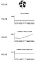
- FIGS. 2A through 2D In order to perform recording on a disk while maintaining a constant rotational speed of the disk without performing speed variation control, it has also been conceived to make the format of information recorded on a disk as shown in FIGS. 2A through 2D . That is, as shown in FIG. 2D , the frequency of a channel clock used in recording of the disk is decreased in the inner tracks and increased in the outer tracks such that the frequency is proportional to the radius position of the track. In this case, since the recording linear velocity becomes small in the inner tracks and large in the outer tracks, the recording linear density is constant as shown in FIG. 2B . In addition, it is possible to record information on the disk while maintaining a constant number of revolutions (rotational speed) of the disk as shown in FIG. 2C , i.e., by using a CAV (Constant Angular Velocity) method.
- CAV Constant Angular Velocity
- a ZCLV method in which an optical disk medium is divided into a plurality of regions (zones) in the radial direction thereof, and the recording speed for each of the zones is varied such that the average number of revolutions (angular velocity) of the disk over the zones becomes constant while maintaining a constant recording linear velocity in each of the zones by using the above-mentioned CLV method.
- the ratio among the pulse width of a recording pulse sequence, heating power, and erase power of a laser emission during recording at a specific recording linear velocity is optimized, and the states of marks and spaces formed vary at a different recording linear velocity.
- the heat capacity of a top heating pulse, which is necessary for formation of a mark may be excessive or deficient
- the average length of marks may be different due to variation in cooling rate
- faulty erasing and degradation of a recording film may occur due to excessive or deficient erase power.
- jitter may be degraded or the number of times of overwriting may be decreased.
- the optimum light volume is obtained at the same recording linear velocity for each of at least two positions in a test-writing region. Then, by performing interpolation or extrapolation with respect to the optimum recording light volumes at the two recording linear velocities obtained by an interpolating routine, the optimum recording light volumes are obtained for all of the recording linear velocities.
- an optical disk in order to provide an optical disk apparatus capable of high-speed and highly-reliable recording, an optical disk, an optical head, synchronization signal generating means, a VCO, phase comparing means, a controller, and recording signal generating means are provided, and the height and width of a pulse of a recording signal is varied in accordance with the recording linear velocity, such that recording can be consistently performed under the best recording conditions.
- Japanese Laid-Open Patent Application No. 2001-118245 discloses a method in which, among a top heating pulse duty ratio Ttop for varying the front edge of the top heating pulse in a recording pulse sequence, an end-off cooling pulse duty ratio Tecp for varying the rear edge of the end-off cooling pulse in the recording pulse sequence, and an erase power ratio E that is the ratio of an erase power Pe with respect to a heating power Pw, at least two of the above-mentioned set values are updated at predetermined intervals. Thereby, even if the recording linear velocity is varied by CAV control that makes the number of revolutions of a disk constant, recording is performed in which uniform characteristics are obtained over the entire surface of a phase change optical disk medium.
- phase change optical disk it is difficult for a phase change optical disk to correspond to a wide-range recording linear velocity. Particularly, in a case where recording is performed at a high recording linear velocity, it is necessary to adjust the length of a recording mark by lowering the level of erase power. Thus, there is a problem in that erase power sufficient for overwriting cannot be supplied.
- the set values of some elements of a recording pulse sequence such as the duty ratio of pulse emission, are varied in accordance with the recording linear velocity as in the CAV method.
- the set values of some elements of a recording pulse sequence such as the duty ratio of pulse emission, are varied in accordance with the recording linear velocity as in the CAV method.
- merely qualitative effects with respect to an optical disk medium are obtained, which are not sufficient for recording disks, particularly, for DVDs.
- US-B-6459666 discloses a technique to change a recording power, a cooling power and a duty of multiple pulses for forming a mark part for forming a recording mark, when performing recording on a phase-change medium (RW) at a different linear velocity (including CAV).
- RW phase-change medium
- CAV linear velocity
- EP-A-1298650 discloses a technique for recording data on an optical recording medium by forming a mark or space by using a recording waveform having an erase pattern containing a multi-pulse.
- a general object of the present invention is to provide an improved and useful information recording method and information recording apparatus in which one or more of the above-mentioned problems are eliminated.
- the invention provides an information recording method and an information recording apparatus in accordance with claims 1 and 8 below respectively.
- Another and more specific object of the present invention is to provide an information recording method and an information recording apparatus that can perform recording while achieving uniform signal characteristics over the entire surface of a phase change optical disk medium having a recording layer whose phase reversibly varies between a crystal phase and an amorphous phase, and that can avoid a decrease in the number of times of overwriting with good overwriting characteristics by using a simple method without performing speed variation control of the rotational speed of the optical disk at the time of recording of information while rotating the optical disk, and while maintaining compatibility with the recording formats of conventional playback-only optical disks.
- a further object of the present invention is to provide an information recording method and an information recording apparatus that are effective in controlling the emitted light volume of a LD at the time of recording to be a constant value by means of a drive circuit.
- an information recording method of performing recording on an optical disk medium having a recording layer on which mark information is recorded by a laser beam emitted in accordance with a waveform based on a recording pulse sequence comprising the steps of:
- the recording linear velocity is varied as in the CAV method and the erase condition of an optical disk medium varies, it is possible to constantly supply a sufficient erase power by using the erase power Pe1 in the multiple pulses without increasing the average erase power.
- the set values of the erase powers Pe1 and Pe2 are sequentially updated (set) at predetermined intervals in accordance with the recording linear velocity, it is possible to perform recording with good overwriting characteristics over an entire surface of the optical disk medium.
- an information recording method of performing recording on an optical disk medium having a recording layer on which mark information is recorded by a laser beam emitted in accordance with a waveform based on a recording pulse sequence comprising the steps of:
- an optimum duty ratio of the pulse width of the erase power is sequentially and constantly updated (set).
- the edge position of the erasing pulse of the erase power Pe1 may be varied in accordance with the recording linear velocity.
- an information recording method of performing recording on an optical disk medium having a recording layer on which mark information is recorded by a laser beam emitted in accordance with a waveform based on a recording pulse sequence comprising the steps of:
- the recording linear velocity is varied as in the CAV method and the erase condition of an optical disk medium varies, it is possible to constantly supply a sufficient erase power by using the erase power Pe1 in the multiple pulses without increasing the average erase power.
- the set values of the eraser powers Pe1 and Pe2 are sequentially updated (set) at predetermined intervals in accordance with the recording linear velocity, it is possible to perform recording with good overwriting characteristics over an entire surface of the optical disk medium.
- the edge position of the erasing pulse of the erase power Pe1 may be varied in accordance with the recording linear velocity.
- the control is easy and the process can be simplified.
- the step of updating may include the step of updating the set values of the erase power Pe1 and the erase power Pe2 at predetermined intervals in accordance with the recording linear velocity such that the difference between the erase power Pe1 and the erase power Pe2 is increased in accordance with an increase in the recording linear velocity.
- an information recording method may further include the step of updating a set value of a duty ratio Te1 of a pulse width of the erase power Pe1 at predetermined intervals in accordance with the recording linear velocity such that the duty ratio Te1 with respect to the cycle of the multiple pulses defined by the erase power Pe1 and the erase power Pe2, where Pe1 > Pe2, is decreased in accordance with an increase in the recording linear velocity.
- the step of updating may include the steps of:
- the step of updating may include the step of reading one of:
- the step of updating may include the steps of:
- the step of updating may include the steps of:
- an information recording apparatus that performs recording on an optical disk medium having a recording layer on which mark information is recorded by a laser beam emitted in accordance with a waveform based on a recording pulse sequence while varying a recording clock cycle T in accordance with a variation in a recording linear velocity such that a recording linear density becomes substantially constant, the information recording apparatus including:
- an information recording apparatus that performs recording on an optical disk medium having a recording layer on which mark information is recorded by a laser beam emitted in accordance with a waveform based on a recording pulse sequence while varying a recording clock cycle T in accordance with a variation in a recording linear velocity such that a recording linear density becomes substantially constant, the information recording apparatus including:
- FIGS. 3A through 8 a description is given below of a first embodiment of the present invention.
- the pulse width is set by: a top heating pulse duty ratio Ttop of the top heating pulse constituting a recording pulse sequence; a duty pulse Tmp of a heating pulse in a multi-pulse part following the top heating pulse; and an end-off cooling pulse duty ratio Tecp of the end-off cooling pulse of the recording pulse sequence.
- recording power is set by heating power Pw, erase power Pe0, and bias power Pb.
- a heating pulse (erasing pulse) in an erasing region, which forms a space part between mark parts is set in more detail by setting a duty ratio Te1 of the erasing pulse for multiple pulses formed by erase power Pe1 and erase power Pe2.
- the erase power ratio ⁇ 0 is reduced compared to a disk corresponding to low speed. This is because even if the erase power is set to a sufficiently high value at which optimum overwriting characteristics are obtained at low speeds, the reflection rate is reduced at high speeds due to formation of an amorphous phase, which is achieved during a cooling state from the time at which the erase power is applied.
- the set values are updated in the following manner so as to perform good recording over the entire surface of a disk.
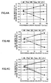
- Specific examples of the set values are as follows. As shown in FIG. 4A , the top heat pulse duty ratio Ttop is varied from 0.55 T ( ⁇ 7.0 ns) at the minimum velocity (the innermost track position) to 0.75 T ( ⁇ 3.5 ns) at the maximum velocity (the outermost track position). That is, the set value (the top heat pulse duty ratio Ttop) is updated (varied) such that the set value is varied by 0.2 T in total.
- the end-off cooling pulse duty ratio Tecp is varied from 0.5 T ( ⁇ 6.4 ns) at the innermost track position to 0.2 T ( ⁇ 1.0 ns) at the outermost track position. That is, the set value (the end-off cooling pulse duty ratio Tecp) is updated (changed) such that the set value is varied by 0.3 T in total. Additionally, the intervals at which the set value of the end-off cooling pulse duty ratio Tecp is updated are the same as those at which the top heat pulse duty ratio Ttop is updated.
- the set value of the erase power ratio ⁇ 0 of the erase power Pe to the heating power Pw is updated (varied) from 0.4 at the innermost track position to 0.5 at the outermost track position, that is, a variation of 0.1 in total.
- each of the set values relating to a recording mark part with respect to the recording linear velocity is calculated by linear approximation (linear expression) by using the set values of the recording linear velocity for two positions: the innermost track position and the outermost track position.
- Each of the set values may be obtained, for example by using the following approximate expressions.
- Ttop T 0.013 ⁇ LV m / s + 0.41
- FIGS. 4B and 4C show cases where each of the set values is updated in stages or at intervals, each stage or interval being approximately 1.0 m/s in the recording linear velocity.
- an erasing pulse part (space part) is set in more detail at a high recording linear velocity.
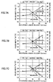
- the duty ratio Te1 of an erasing pulse having the erase power of Pe1 is 1 ( ⁇ 12.7 ns) at the innermost track position but is varied from 0.8 T ( ⁇ 5.9 ns) at an intermediate track position (intermediate track speed) to 0.3 T ( ⁇ 1.6 ns) at the outermost track position. That is, the set value of the duty ratio Te1 is updated (varied) such that the set value is decreased by 0.7 T in total.
- the duty ratio Te1 of an erasing pulse of the erase power Pe1 is not linearly varied in the range from the innermost track position to the outermost track position. This is because, in a case where recording is performed on a phase change optical disk at the recording linear velocity that is varied in a wide range as mentioned above, it is possible to achieve both overwriting characteristics and jitter characteristics (reproduction signal quality) at a low recording linear velocity even if erasing pulses are of a constant power level. However, at a high recording linear velocity, it is necessary to form an erasing pulse by multiple pulses defined by: a high erase power Pe1, which is a high erasing level; and a low erase power Pe2, which can reduce the average erasing power.
- the duty ratio Te1 of the erase power is decreased or/and the range is set where the difference between the erase power Pe1 and the erase power Pe2 is increased.
- the range may be set where the difference between the ratios ⁇ 1 and ⁇ 2 of the erase power is increased.
- various applicable ranges may be used for the recording linear velocity of a phase change optical disk. It is possible to determine the set values relating to an erasing pulse at an arbitrary recording linear velocity based on the parameters (the duty ratio Te1 and the power ratios ⁇ 1 and ⁇ 2) composing erasing pulses that correspond to the recording linear velocities of at least three positions.
- the parameters the duty ratio Te1 and the power ratios ⁇ 1 and ⁇ 2
- a region that requires multiple pulses as an erasing pulse is derived from linear approximation (linear expression) by using two kinds of the set values: the set values at the intermediate velocity and those at the maximum velocity.
- Each of the parameters may be obtained, for example, by using the following approximations.
- the duty ratio of an erasing pulse composed by multiple pulses may be set to a fixed value, and only the set values of the erase powers Pe1 and Pe2 may be updated in accordance with the variation of the recording linear velocity.
- the erase power ratios ⁇ 1 and ⁇ 2 so as to achieve a desired erase power level, it is possible to perform recording while practically preventing degradation of jitter characteristics and overwriting characteristics.
- the erase power Pe1 (or ⁇ 1) and the erase power Pe2 (or ⁇ 2) of an erasing pulse composed by multiple pulses may be set to fixed values, and the set value of the duty ratio Te1, which is the pulse width of the erase power Pe1 with respect to the multi-pulse cycle, may be updated in accordance with the variation of the recording linear velocity.
- the duty ratio Te1 of an erasing pulse so as to match erase power levels serving as execution values, it is possible to perform recording while practically preventing degradation of jitter characteristics and overwriting characteristics.
- the recording speed for a phase change optical disk depends on the crystallization speed of the material of a recording layer. For this reason, there exists two kinds of ranges for the recording linear velocity: a range allowing good erasing with a single erasing pulse and erase power; and a range allowing the optimum erasing without faulty erasing with multiple erasing pulses and erase powers as shown in FIG. 5B . Accordingly, at least in the recording linear velocity range in which multiple erasing pulses are used, the erase power Pe1 is increased, which is the higher erase power and affects the overwriting characteristics, to a further higher power in accordance with the increase of the recording linear velocity.
- the erase power Pe2 is decreased, which is the lower erase power, to a further lower power in accordance with the increase of the recording linear velocity. That is, in yet another embodiment of the present invention, by increasing the difference between the erase power Pe1 and the erase power Pe2, i.e., by decreasing the duty ratio Te1, in accordance with the increase of the recording linear velocity, it is possible to achieve both the overwriting characteristics and the jitter characteristics.
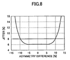
- the asymmetry is the value obtained by normalizing the difference between the average level of the longest data amplitude of the RF signal and the average level of the shortest data amplitude thereof by the longest data amplitude.
- the asymmetry represents the asymmetry between the mark length and the space length.
- the heating power Pw and the erase power ratio ⁇ 0 the most preferred values thereof may be obtained in accordance with the recording linear velocity by test writing (OPC).
- OPC recording linear velocity by test writing
- different setting values of the heating power Pw and the erase power ratio ⁇ 0 may be set for the minimum velocity (at the innermost track position), the maximum velocity (at the outermost track position), and the intermediate velocity.
- Each of the above-mentioned set values (the erase powers Pe1 and Pe2, and the duty ratio Te1, which is the width of an erasing pulse) has its own effects. However, since characteristic variation of the RF signal has interaction, it is preferable to update at least two of the set values. As will be appreciated, it is most effective to update all of the three set values as in this embodiment.
- each of the above-mentioned set values is a typical value of a phase change optical disk and may be set to a different value by, for example, various tunings and various compositions of a material of the recording layer.
- phase change optical disks there has been used, for example, the recording layer of the GeSbTe system, the GeTeSbS system, the TeGeSnAu system, the GeTeSn system, the SbSe system, the SbSeTe system, the SnSeTe system, the GaSeTe system, the GaSeTeGe system, the GaGeSbTe system, the GaSb system, the InSe system, the InSeTe system, and the AgInSbTe system.
- a material of the AgInSbTe system is used for the recording layer.
- phase change optical disk formation of an amorphous phase highly depends on change in a rapid cooling condition of heating ⁇ cooling caused by variation in the recording linear velocity, and the state of a crystal depends on change of cooling ⁇ heating caused by variation in the recording linear velocity, which affects the overwriting characteristics. That is, the shape and size of a mark is affected by the top heating pulse duty ratio Ttop and the end-off cooling pulse duty ratio Tecp, corresponding to the front and rear edge portions of the mark, respectively, and the erase power ratio ⁇ 0. Additionally, the noise level (jitter characteristics) of a space part is affected by the erase power level during an erasing pulse period.
- a wobbled groove is formed on a phase change optical disk for obtaining a tracking error signal (push-pull signal).
- Wobble signals obtained from the wobble of the groove are superimposed.
- Each of the wobble signals is detected by a programmable BPF (Band Pass Filter) at each recording linear velocity, as is described below.
- the wobble signals include address information coded by frequency modulation or phase modulation. By demodulating the address information, it is possible to obtain as the pre-format information the address information and disk information that are inherent to a disk even from an unrecorded disk.
- a method is also known in which such information is generated from intermittent pits (Land Pre-Pit signal) provided in a land portion of a disk.
- step S1 the pre-format information or the recording condition information is read so as to obtain the optimum setting values for each recording linear velocity. Then, in step S2, the variations (or the inclinations) of the set values that are linearly approximated (linear expression) with respect to arbitrary recording linear velocities are calculated. It should be noted that the variations or the inclinations may be calculated in accordance with the characteristics of an optical disk medium, and may be calculated by an approximate expression (quadratic expression) other than linear approximation.
- step S3 update intervals for the set values are calculated from the range of the recording linear velocity in the entire surface of a disk as in the CAV method (in this embodiment, the interval is set to approximately 1.0 m/s).
- the variations of the set values thus obtained are in relation to the recording linear velocity.
- the variations are recognized, for example, in relation to arbitrary address information during recording, which is obtained by demodulation of the above-mentioned wobble signal and the LPP signal.
- Specific addresses are determined from the innermost track position to the outermost track position and can be associated with the recording linear velocity. Therefore, in step S4, the intervals at which the set values are updated and the ranges of addresses corresponding to the intervals are associated. Thereby, it is possible to update the set values, as in step S5, when the addresses at which the set values are to be updated are reached.
- step S7 it is determined in step S7 whether the current address in recording falls within the current set range.
- the set values are updated to newly calculated values in steps S4 and S5.
- step S9 it is determined whether the address of the end of recording is reached.
- the decision result in step S9 is NO, the process returns to step S6. Similar processes are repeated until the address of the end of recording is reached (YES in step S9).
- the decision result in step S9 is YES, the recording ends.
- This embodiment relates to an information recording apparatus for performing recording on a phase change optical disk medium 1 by using the information recording method in which the set values of the duty ratio Te1 of the width of an erasing pulse and the erase powers Pe1 and Pe2 for dividing the erasing pulse part (space part) into multiple pulses are updated in accordance with the variation in the recording linear velocity.
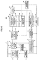
- FIG. 10 is a block diagram showing an information recording apparatus 100 according to the third embodiment of the present invention.
- the information recording apparatus 100 includes: a spindle motor 2, a rotation mechanism 3, an optical head 5; an actuator mechanism 6; a servo mechanism 7; a wobble detector 9; an address demodulation circuit 10; a recording clock generator 12; a drive controller 13; a system controller 14; an EFM encoder 15; an erasing pulse sequence controller 16; and a LD driver 17.
- the rotation mechanism 3 includes the spindle motor 2 that rotates the optical disk medium 1.
- the optical head 5 is provided with: a light receiving part; an objective lens for converging laser light with respect to the optical disk medium 1; and a light source such as a semiconductor laser (LD) 4.
- the optical head 5 performs tracking along a track (groove).
- the actuator mechanism 6, which drives the objective lens of the optical head 5, is radially movable for seeking.
- the rotation mechanism 3 and the actuator mechanism 6 are connected to the servo mechanism 7.
- the optical head 5 is connected to the wobble detector 9 including a programmable BPF 8.
- the wobble detector 9 is connected to the address demodulation circuit 10, which demodulates an address from a detected wobble signal.
- the address demodulation circuit 10 is connected to the recording clock generator 12 including a PLL synthesizer circuit 11.
- the PLL synthesizer circuit 11 is connected to the drive controller 13.
- the drive controller 13 is connected to the system controller 14.
- the drive controller 13 is also connected to the servo mechanism 7, the wobble detector 9, and the address demodulation circuit 10.
- the system controller 14 is connected to the EFM encoder 15, the recording/erasing pulse sequence controller 16, and the LD driver 17.
- the recording/erasing pulse sequence controller 16 includes:
- the center frequency of the BPF corresponding to the recording linear velocity is set to the programmable BPF 8 by the drive controller 13.
- Addresses are demodulated by the address demodulation circuit 10 from the wobble signal detected by the wobble detector 9.
- a recording channel clock at an arbitrary recording linear velocity is generated by the PLL synthesizer circuit 11, whose basic clock frequency is varied by the drive controller 13, and is output to the recording/erasing pulse sequence controller 16.
- the recording channel clock and EFM data which are recording information, are input to the recording/erasing pulse sequence controller 16 from the recording clock generator 12 and the EFM encoder 15, respectively.
- the heating pulse generator 18 of the recording/erasing pulse sequence controller 16 generates the heating pulse control signal including top heating pulses and heating pulses in multi-pulse parts following the top heating pulses.
- the erasing pulse generator 19 generates from the EFM data the erasing pulse control signal including erasing pulses having multi-pulse structures.
- the LD driver 17 performs switching of the respective drive current sources 22 for the heating power Pw, the erase powers Pe1 and Pe2, and the bias power Pb.
- a recording pulse sequence control signal formed by the top heating pulse control signal, the heating pulse control signal of multi-pulse parts following the top pulses, and the end-off cooling pulse control signal.
- the recording pulse sequence control signal is generated by arranging a multi-stage delay (gate delay) element having the delay amount of about 0.3 ns in a top heating pulse generator in the heating pulse generator 18, generating a plurality of edge pulses from the EFM data, inputting the generated multi-stage edge pulse into the edge selector 20 formed by a multiplexer, and varying the front edges and the rear edges by edge pulses selected by the system controller 14.
- the erasing pulse generator 19 generates the erasing pulse control signal whose duty ratio Te1 of the width of an erasing pulse is set to a calculated target duty ratio by edge pulses selected by the system controller 14.
- the information recording apparatus of this embodiment with a simple and small circuit configuration, it is possible to easily update(set) the set values including the top heating pulse duty ratio Ttop, the end-off cooling pulse duty ratio Tecp, the erase power ratio ⁇ 1, the erase powers Pe1 and Pe2 in erasing regions, and the duty ratio Te1 of the width of an erasing pulse.
- the set values including the top heating pulse duty ratio Ttop, the end-off cooling pulse duty ratio Tecp, the erase power ratio ⁇ 1, the erase powers Pe1 and Pe2 in erasing regions, and the duty ratio Te1 of the width of an erasing pulse.
- each of the set values is determined as in the above-mentioned information recording method, an optimum edge pulse is selected at a desired recording linear velocity, and a desired recording pulse is generated. Additionally, when the generated erasing pulse is updated at predetermined intervals, each of the set values is varied in a stair-like pattern as shown in FIGS. 6B and 7B .
- each pulse width becomes a fixed value, and the duty ratio of the pulse width is varied in accordance with the variation in the recording channel clock.
- a pulse edge generator having a PLL structure may be used that uses a phase comparator, a loop filter, a VCO (voltage controlled oscillator), and a divider.
- a high resolution clock which is 20 times the frequency of the recording channel clock, is generated by the PLL, and the pulse edge signal has a resolution of about 0.05 T.
- the pulse edge generator 21 may be a ring oscillator that is formed by a plurality of number of voltage-control type delay elements in series and performs voltage control such that a final stage signal becomes a clock of desired times by a phase comparator and a loop filter.
- each of the set values is determined as in the above-mentioned information recording method, an optimum edge pulse for a desired recording linear velocity is selected, and desired erasing pulses are generated.
- the set value of each pulse width during an update interval is varied in a sawtooth shape as shown in FIGS. 4C , 6C and 7C .
- each of the set values during an update interval becomes a constant value with respect to the variation in the recording clock frequency as shown in FIGS. 4B , 6B and 7B .
- the information recording apparatus of this embodiment with a simple and small circuit configuration, it is possible to perform recording according to the CAV control using the information recording method that includes updating of the duty ratio Te1 of the pulse width of an erasing pulse, and the erase powers Pe1 and Pe2.
- the description is given above by taking an example where the present invention is applied to the CAV method, the present invention may also be similarly applied to the ZCLV method.
- the recording linear velocity is varied as in the CAV method and the erase condition of an optical disk medium varies, it is possible to constantly supply a sufficient erase power by using the erase power Pe1 in the multiple pulses without increasing the average erase power.
- the set values of the eraser powers Pe1 and Pe2 are sequentially updated (set) at predetermined intervals in accordance with the recording linear velocity, it is possible to perform recording with good overwriting characteristics over an entire surface of the optical disk medium.
- an optimum duty ratio of the pulse width of the erase power is sequentially and constantly updated (set).
- the edge position of the erasing pulse of the erase power Pe1 may be varied in accordance with the recording linear velocity.
- the recording linear velocity is varied as in the CAV method and the erase condition of an optical disk medium varies, it is possible to constantly supply a sufficient erase power by using the erase power Pe1 in the multiple pulses without increasing the average erase power.
- the set values of the eraser powers Pe1 and Pe2 are sequentially updated (set) at predetermined intervals in accordance with the recording linear velocity, it is possible to perform recording with good overwriting characteristics over an entire surface of the optical disk medium.
- the edge position of the erasing pulse of the erase power Pe1 may be varied in accordance with the recording linear velocity.
- the erase power Pe1 which is the higher power and affects the overwriting characteristics
- the erase power Pe2 which is the lower power
- the erase power Pe1 and Pe2 is increased to a higher power in accordance with an increase in the recording linear velocity.
- the erase power Pe2 which is the lower power
- the difference between the erase powers Pe1 and Pe2 in accordance with the increase in the recording linear velocity it is possible to achieve both overwriting characteristics and jitter characteristics.
- the erase power Pe1 which is the higher power and affects the overwriting characteristics
- the erase power Pe2 which is the lower power
- the duty ratio Te1 of the pulse width of the erase power Pe1 with respect to the cycle of the multiple pulses in accordance with the increase in the recording linear velocity, it is possible to achieve both overwriting characteristics and jitter characteristics.
- the present invention even in a case where recording or overwriting is performed on the optical disk medium, by using the optimum set values that are obtained from the optimum set values recorded in a previous time, it is possible to determine the minimum intervals for updating the set values without calculating again the erase power values and the duty ratio of the pulse width of the erasing pulse formed by the multiple pulses. Thus, it is possible to reduce the process time required until recording is started. Also, it is possible to perform recording with uniform characteristics over an entire surface of the optical disk by a simple method.
- the present invention even during recording, it is possible to easily and accurately determine the intervals for updating the set values such that the calculated optimum set values of an erasing pulse sequence formed by multiple pulses are not shifted.
- the recording linear velocity is varied and the erase condition of an optical disk medium varies as in the CAV method, it is possible to constantly update with a high degree of accuracy the optimum erase powers and the optimum duty ratio of the pulse width of the erasing pulse.
- an information recording method such as the CAV method, in which the recording linear velocity is varied is used for an optical disk medium corresponding to a wide range of the recording linear velocity, it is possible to perform recording with good overwriting characteristics over an entire surface of the optical disk medium with a simple and small circuit configuration.
- an information recording method such as the CAV method, in which the recording linear velocity is varied is used for an optical disk medium corresponding to a wide range of the recording linear velocity
Claims (9)
- Procédé d'enregistrement d'informations pour effectuer un enregistrement sur un support de disque optique (1) possédant une couche d'enregistrement sur laquelle une information de marque est enregistrée par un faisceau laser émis conformément à une forme d'onde en fonction d'une séquence d'impulsion d'enregistrement, ledit procédé d'enregistrement d'information comporte les étapes consistant à :effectuer un enregistrement tout en faisant varier un cycle d'horloge d'enregistrement T conformément à une variation d'une vitesse linéaire d'enregistrement de sorte qu'une densité linéaire d'enregistrement devient sensiblement constante ; etcaractérisé en ce que lorsqu'un enregistrement est effectué en utilisant de multiples impulsions définies par une puissance d'effacement Pe1 et une puissance d'effacement Pe2 en tant qu'impulsion d'effacement pour former une partie d'espace entre des parties de marques, mettre à jour des valeurs fixées de la puissance d'effacement Pe1 et de la valeur d'effacement Pe2 à des intervalles prédéterminés conformément à la vitesse linéaire d'enregistrement, de sorte que la différence entre la puissance d'effacement Pe1 et la puissance d'effacement Pe2 est augmentée conformément à une augmentation de la vitesse linéaire d'enregistrement.
- Procédé d'enregistrement d'informations selon la revendication 1, dans lequel l'étape de mise à jour comporte l'étape de mise à jour des valeurs fixées d'un coefficient ε1 et d'un coefficient ε2 à des intervalles prédéterminés conformément à la vitesse linéaire d'enregistrement de sorte que la différence entre le coefficient ε1 et le coefficient ε2 est augmentée conformément à une augmentation de la vitesse linéaire d'enregistrement, où, lorsqu'une puissance d'effacement Pe0 pour une unique impulsion d'effacement est une puissance cible, la puissance d'effacement Pe1 est définie par Pe1 = ε1 x Pe0, et la puissance d'effacement Pe2 est définie par Pe2 = ε2 x Pe0.
- Procédé d'enregistrement d'informations selon la revendication 1, comportant en outre l'étape de la mise à jour d'une valeur fixée d'un rapport cyclique Te1 d'une largeur d'impulsion de la puissance d'effacement Pe1 à des intervalles prédéterminés conformément à la vitesse linéaire d'enregistrement de sorte que le rapport cyclique Te1 par rapport au cycle d'impulsions multiples défini par la puissance d'effacement Pe1 et la puissance d'effacement Pe2, où Pe1 > Pe2, est réduit conformément à une augmentation de la vitesse linéaire d'enregistrement.
- Procédé d'enregistrement d'informations selon la revendication 1, dans lequel l'étape de mise à jour comporte les étapes consistant à :mettre à jour une valeur fixée d'un rapport cyclique Te1 d'une largeur d'impulsion de la puissance d'effacement Pe1 à des intervalles prédéterminés conformément à la vitesse linéaire d'enregistrement ;détecter les valeurs d'indice qui sont préformatées sur le support de disque optique (1) d'une pluralité de vitesses linéaires d'enregistrement, la puissance d'effacement Pe1 et la puissance d'effacement Pe2 correspondant aux vitesses linéaires d'enregistrement, et le rapport cyclique Te1 d'une largeur d'impulsion de l'impulsion d'effacement correspondant aux vitesses linéaires d'enregistrement ;calculer les variations des valeurs fixées de la puissance d'effacement Pe1, la puissance d'effacement Pe2, et le rapport cyclique Te1 qui sont mises à jour à des intervalles prédéterminés en fonction des valeurs d'indice détectés ; etdéterminer la puissance d'effacement Pe1 et la puissance d'effacement Pe2 par rapport à la vitesse linéaire d'enregistrement désirée.
- Procédé d'enregistrement d'informations selon la revendication 1, dans lequel l'étape de mise à jour comporte:la mise à jour d'une valeur fixée d'un rapport cyclique Te1 d'une largeur d'impulsion de la puissance d'effacement Pe1 à des intervalles prédéterminés conformément à la vitesse linéaire d'enregistrement ;la lecture d'une parmi :des premières valeurs fixées optimum : d'une pluralité de vitesses d'enregistrement linéaires ; des puissances d'effacement Pe1 et des puissances d'effacement Pe2 correspondant aux vitesses linéaires d'enregistrement ; et des rapports cycliques Te1 de la largeur d'impulsion correspondant aux vitesses linéaires d'enregistrement, lesdites premières valeurs fixées optimum étant comprises dans l'information de disque préalablement enregistrée dans une zone prédéterminée du support de disque optique (1) dans le passé ; etdes secondes valeurs fixées optimum : d'une pluralité de vitesses linéaires d'enregistrement ; des puissances d'effacement Pe1 et des puissances d'effacement Pe2 correspondant aux vitesses linéaires d'enregistrement ; et des rapports cycliques Te1 de la largeur d'impulsion correspondant aux vitesses linéaires d'enregistrement, lesdites secondes valeurs fixées optimum étant mémorisées dans un appareil d'enregistrement d'informations préalablement, etla détermination de la puissance d'effacement Pe1 et de la puissance d'effacement Pe2 par rapport à la vitesse linéaire d'enregistrement en calculant les variations des valeurs fixées : de la puissance d'effacement Pe1 ; de la puissance d'effacement Pe2 ; et du rapport cyclique Te1 de la largeur d'impulsion, qui sont mises à jour à des intervalles prédéterminés, en fonction de l'une parmi les premières et secondes valeurs fixées optimum qui sont lues.
- Procédé d'enregistrement d'informations selon la revendication 1, dans lequel l'étape de mise à jour comporte les étapes consistant à :mettre à jour une valeur fixée de rapport cyclique Te1 d'une largeur d'impulsion de la puissance d'effacement Pe1 à des intervalles prédéterminés conformément à la vitesse linéaire d'enregistrement ;détecter une information d'adresse qui est pré-formatée sur le support de disque optique (1) ;calculer les valeurs fixées de la puissance d'effacement Pe1, de la puissance d'effacement Pe2, et d'un rapport cyclique Te1 d'une largeur d'impulsion de l'impulsion d'effacement par rapport à l'information d'adresse correspondant à la vitesse linéaire d'enregistrement à partir des variations des valeurs fixées qui sont mises à jour à des intervalles prédéterminés ; etcalculer les valeurs fixées de la puissance d'effacement Pe1, de la puissance d'effacement Pe2, et du rapport cyclique Te1 par rapport à l'information d'adresse désirée en associant les intervalles prédéterminés aux plages correspondantes de l'information d'adresse.
- Procédé d'enregistrement d'informations selon la revendication 1, dans lequel l'étape de mise à jour comporte les étapes consistant à :mettre à jour une valeur fixée d'un rapport cyclique Te1 d'une largeur d'impulsion de la puissance d'effacement Pe1 à des intervalles prédéterminés conformément à la vitesse linéaire d'enregistrement ;détecter l'une des valeurs d'indice ou des valeurs fixées optimum : d'une pluralité de vitesses linéaires d'enregietrement ; et de la puissance d'effacement Pe1, de la puissance d'effacement Pe2, et d'un rapport cyclique Te1 d'une largeur d'impulsion de l'impulsion d'effacement qui correspondent aux vitesses linéaires d'enregistrement ; etcalculer les variations des valeurs fixées de la puissance d'effacement Pe1, de la puissance d'effacement Pe2, et du rapport cyclique Te1 qui sont mises à jour à des intervalles prédéterminés par l'une d'une approximation de fonction linéaire ou d'une approximation de fonction quadratique en fonction de l'une détectée des valeurs d'indice ou des valeurs fixées optimum.
- Appareil d'enregistrement d'informations qui effectue l'enregistrement sur un support de disque optique (1) possédant une couche d'enregistrement sur laquelle une information de marque est enregistrée par un faisceau laser émis conformément à une forme d'onde en fonction d'une séquence d'impulsion d'enregistrement tout en faisant varier un cycle d'horloge d'enregistrement T conformément à une variation d'une vitesse linéaire d'enregistrement de sorte qu'une densité linéaire d'enregistrement devient sensiblement constante, ledit appareil d'enregistrement d'informations étant caractérisé en ce qu'il comporte :un contrôleur (14) qui, lorsqu'un enregistrement est effectué en utilisant une pluralité d'impulsions multiples définies par une puissance d'effacement Pe1 et une puissance d'effacement Pe2 en tant qu'impulsion d'effacement pour former une partie d'espace entre des parties de marques, met à jour les valeurs fixées d'une puissance d'effacement Pe1 et d'une puissance d'effacement Pe2 à des intervalles prédéterminés conformément à la vitesse linéaire d'enregistrement, de sorte que la différence entre la puissance d'effacement Pe1 et la puissance d'effacement Pe2 est augmentée conformément à une augmentation de la vitesse linéaire d'enregistrement ;une partie de variation de largeur d'impulsion (16) qui fait varier une position d'un bord de l'impulsion d'effacement pour les impulsions multiples conformément au rapport cyclique Te1 mis à jour ; etun circuit de commande (17) qui met à jour et contrôle une quantité de lumière émise depuis une source de lumière laser conformément à la puissance d'effacement Pe1 mise à jour et la puissance d'effacement Pe2 mise à jour.
- Appareil d'enregistrement d'informations selon la revendication 8, dans lequel le contrôleur (14) est agencé pour mettre à jour à des intervalles prédéterminés les valeurs fixées de Pe1 et de Pe2 et pour mettre à jour un rapport cyclique Te1 d'une largeur d'impulsion de la puissance d'effacement Pe1 par rapport au cycle d'impulsions multiples.
Applications Claiming Priority (2)
| Application Number | Priority Date | Filing Date | Title |
|---|---|---|---|
| JP2003196865 | 2003-07-15 | ||
| JP2003196865A JP4602648B2 (ja) | 2003-07-15 | 2003-07-15 | 情報記録方法及び情報記録装置 |
Publications (3)
| Publication Number | Publication Date |
|---|---|
| EP1498885A2 EP1498885A2 (fr) | 2005-01-19 |
| EP1498885A3 EP1498885A3 (fr) | 2007-10-10 |
| EP1498885B1 true EP1498885B1 (fr) | 2009-04-29 |
Family
ID=33475486
Family Applications (1)
| Application Number | Title | Priority Date | Filing Date |
|---|---|---|---|
| EP04253990A Expired - Fee Related EP1498885B1 (fr) | 2003-07-15 | 2004-07-01 | Procédé d'enregistrement d'informations et appareil d'enregistrement d'informations |
Country Status (4)
| Country | Link |
|---|---|
| US (2) | US7426166B2 (fr) |
| EP (1) | EP1498885B1 (fr) |
| JP (1) | JP4602648B2 (fr) |
| DE (1) | DE602004020842D1 (fr) |
Families Citing this family (12)
| Publication number | Priority date | Publication date | Assignee | Title |
|---|---|---|---|---|
| KR20040111623A (ko) * | 2002-05-17 | 2004-12-31 | 티디케이가부시기가이샤 | 광기록 매체에의 데이터의 기록 방법, 광기록 매체에의데이터의 기록 장치 및 광기록 매체 |
| JP3954438B2 (ja) * | 2002-05-31 | 2007-08-08 | Tdk株式会社 | 光記録媒体への情報記録方法、情報記録装置及び光記録媒体 |
| EP1557828B1 (fr) * | 2002-10-28 | 2010-08-11 | Panasonic Corporation | Procede d'enregistrement d'information optique et dispositif d'enregistrement d'information optique |
| JP3740151B2 (ja) | 2003-08-27 | 2006-02-01 | 株式会社リコー | 光記録方法及び光記録装置 |
| JP2006252729A (ja) * | 2005-03-14 | 2006-09-21 | Hitachi-Lg Data Storage Inc | 光ディスク装置及びその記録情報の消去方法 |
| JP2007109368A (ja) * | 2005-09-14 | 2007-04-26 | Ricoh Co Ltd | 色素系追記型光記録媒体の記録方法、記録媒体、及び記録装置 |
| JP2007334921A (ja) * | 2006-06-12 | 2007-12-27 | Hitachi Ltd | 記録方法、レーザ駆動装置及びそれらを用いた光ディスク装置 |
| JP4512582B2 (ja) * | 2006-12-07 | 2010-07-28 | 株式会社日立製作所 | 記録再生方法、及び、記録再生装置 |
| JP2009151862A (ja) * | 2007-12-20 | 2009-07-09 | Hitachi-Lg Data Storage Inc | 光ディスク装置及びオーバーライトパワー制御方法 |
| JP2009245557A (ja) * | 2008-03-31 | 2009-10-22 | Toshiba Corp | 情報記録方法および情報記録装置 |
| JP2011118996A (ja) * | 2009-12-04 | 2011-06-16 | Hitachi-Lg Data Storage Inc | 光学式記録媒体の記録装置、及び光学式記録媒体の記録方法 |
| US9368218B2 (en) * | 2014-10-03 | 2016-06-14 | HGST Netherlands B.V. | Fast secure erase in a flash system |
Family Cites Families (22)
| Publication number | Priority date | Publication date | Assignee | Title |
|---|---|---|---|---|
| US4984873A (en) | 1987-08-31 | 1991-01-15 | Ricoh Company, Ltd. | Liquid crystal display device |
| US5056896A (en) | 1988-08-29 | 1991-10-15 | Ricoh Company, Ltd. | Liquid crystal display device with dielectric anisotropy |
| JP2707774B2 (ja) | 1989-12-13 | 1998-02-04 | 松下電器産業株式会社 | 光学情報の記録方法および記録装置 |
| JP3039099B2 (ja) | 1992-02-14 | 2000-05-08 | ソニー株式会社 | 光ディスク記録装置およびその方法 |
| JPH05274678A (ja) | 1992-03-27 | 1993-10-22 | Canon Inc | 光ディスクに情報を記録する方法及び装置 |
| US5732062A (en) | 1995-10-16 | 1998-03-24 | Ricoh Company, Ltd. | Information recording apparatus, method and computer program product |
| JPH10106008A (ja) | 1996-09-30 | 1998-04-24 | Seiko Epson Corp | 光ディスク装置 |
| US7239602B2 (en) | 1998-08-27 | 2007-07-03 | Ricoh Company, Ltd. | Optical information recording medium with a partition wall between an information tracks groove and a preformat pit encoding information therefor |
| JP4063978B2 (ja) | 1998-07-03 | 2008-03-19 | 株式会社リコー | 情報記録方法 |
| JP3734621B2 (ja) | 1998-07-03 | 2006-01-11 | 株式会社リコー | 光情報記録方法及びその装置 |
| US6487149B1 (en) | 1998-10-09 | 2002-11-26 | Ricoh Company, Ltd. | Optical recording and reproducing methods for optical disk |
| JP2001243626A (ja) | 2000-02-24 | 2001-09-07 | Ricoh Co Ltd | 情報記録方法、情報記録装置及び情報処理装置 |
| US6459666B1 (en) | 1999-09-06 | 2002-10-01 | Ricoh Company, Ltd. | Information recording apparatus and method |
| US6771577B2 (en) | 1999-09-06 | 2004-08-03 | Ricoh Company, Ltd. | Information recording apparatus and method |
| JP2001118245A (ja) | 1999-10-14 | 2001-04-27 | Ricoh Co Ltd | 情報記録方法及びその装置 |
| EP1206772B1 (fr) | 2000-05-09 | 2009-03-25 | Koninklijke Philips Electronics N.V. | Procede et dispositif d'enregistrement d'un signal d'information sur une couche d'information d'un support d'enregistrement |
| US6664526B2 (en) | 2000-11-15 | 2003-12-16 | Ricoh Company, Ltd. | Optical information recording employing improved recording power control scheme |
| JP3921046B2 (ja) | 2000-12-07 | 2007-05-30 | 株式会社日立製作所 | 情報記録方法及び光ディスク装置 |
| US6801240B2 (en) | 2001-04-12 | 2004-10-05 | Ricoh Company, Ltd. | Information recording with effective pulse control scheme |
| TWI251234B (en) | 2001-09-29 | 2006-03-11 | Samsung Electronics Co Ltd | Apparatus for recording data on optical recording medium |
| JP2003157536A (ja) | 2001-11-16 | 2003-05-30 | Ricoh Co Ltd | 光情報記録媒体への記録方法及び装置 |
| JP3521141B2 (ja) | 2002-01-08 | 2004-04-19 | 株式会社リコー | 情報記録装置 |
-
2003
- 2003-07-15 JP JP2003196865A patent/JP4602648B2/ja not_active Expired - Fee Related
-
2004
- 2004-06-25 US US10/875,167 patent/US7426166B2/en active Active
- 2004-07-01 DE DE602004020842T patent/DE602004020842D1/de active Active
- 2004-07-01 EP EP04253990A patent/EP1498885B1/fr not_active Expired - Fee Related
-
2008
- 2008-05-23 US US12/153,808 patent/US7848201B2/en not_active Expired - Fee Related
Also Published As
| Publication number | Publication date |
|---|---|
| DE602004020842D1 (de) | 2009-06-10 |
| EP1498885A3 (fr) | 2007-10-10 |
| US7426166B2 (en) | 2008-09-16 |
| JP4602648B2 (ja) | 2010-12-22 |
| EP1498885A2 (fr) | 2005-01-19 |
| JP2005038455A (ja) | 2005-02-10 |
| US20080253253A1 (en) | 2008-10-16 |
| US7848201B2 (en) | 2010-12-07 |
| US20050013229A1 (en) | 2005-01-20 |
Similar Documents
| Publication | Publication Date | Title |
|---|---|---|
| US7848201B2 (en) | Information recording apparatus that can achieve uniform signal characteristics and overwriting characteristics over an entire surface of an optical disk medium | |
| US6459666B1 (en) | Information recording apparatus and method | |
| US7019273B2 (en) | Optical information recording employing improved recording power control scheme | |
| US7388821B2 (en) | Information recording device | |
| US6771577B2 (en) | Information recording apparatus and method | |
| US7724628B2 (en) | Method and apparatus for recording data on optical recording medium | |
| JP4063978B2 (ja) | 情報記録方法 | |
| JP4480295B2 (ja) | 情報記録方法、情報記録装置及び情報処理装置 | |
| JP2001243626A (ja) | 情報記録方法、情報記録装置及び情報処理装置 | |
| JP2001118245A (ja) | 情報記録方法及びその装置 | |
| JP2001076341A (ja) | 情報記録方法及びその装置 | |
| JP2002208139A (ja) | 情報記録方法、情報記録装置及び情報処理装置 | |
| JP4139280B2 (ja) | 情報記録方法、情報記録装置及び情報処理装置 | |
| JP2001297436A (ja) | 情報記録方法、情報記録装置及び情報処理装置 | |
| JP3740151B2 (ja) | 光記録方法及び光記録装置 | |
| US20080069158A1 (en) | Laser power control technique and apparatus for recording and reproducing data in and from optical disk under laser power control | |
| JP2001110053A (ja) | 情報記録方法及びその装置 | |
| JP2007095303A (ja) | 情報記録方法、情報記録装置及び情報処理装置 | |
| JP2004030914A (ja) | 情報記録装置 |
Legal Events
| Date | Code | Title | Description |
|---|---|---|---|
| PUAI | Public reference made under article 153(3) epc to a published international application that has entered the european phase |
Free format text: ORIGINAL CODE: 0009012 |
|
| 17P | Request for examination filed |
Effective date: 20040722 |
|
| AK | Designated contracting states |
Kind code of ref document: A2 Designated state(s): AT BE BG CH CY CZ DE DK EE ES FI FR GB GR HU IE IT LI LU MC NL PL PT RO SE SI SK TR |
|
| AX | Request for extension of the european patent |
Extension state: AL HR LT LV MK |
|
| PUAL | Search report despatched |
Free format text: ORIGINAL CODE: 0009013 |
|
| AK | Designated contracting states |
Kind code of ref document: A3 Designated state(s): AT BE BG CH CY CZ DE DK EE ES FI FR GB GR HU IE IT LI LU MC NL PL PT RO SE SI SK TR |
|
| AX | Request for extension of the european patent |
Extension state: AL HR LT LV MK |
|
| 17Q | First examination report despatched |
Effective date: 20080414 |
|
| AKX | Designation fees paid |
Designated state(s): DE ES FR GB IT NL |
|
| GRAP | Despatch of communication of intention to grant a patent |
Free format text: ORIGINAL CODE: EPIDOSNIGR1 |
|
| RAP1 | Party data changed (applicant data changed or rights of an application transferred) |
Owner name: RICOH COMPANY, LTD. |
|
| GRAS | Grant fee paid |
Free format text: ORIGINAL CODE: EPIDOSNIGR3 |
|
| GRAA | (expected) grant |
Free format text: ORIGINAL CODE: 0009210 |
|
| AK | Designated contracting states |
Kind code of ref document: B1 Designated state(s): DE ES FR GB IT NL |
|
| REG | Reference to a national code |
Ref country code: GB Ref legal event code: FG4D |
|
| REF | Corresponds to: |
Ref document number: 602004020842 Country of ref document: DE Date of ref document: 20090610 Kind code of ref document: P |
|
| NLV1 | Nl: lapsed or annulled due to failure to fulfill the requirements of art. 29p and 29m of the patents act | ||
| PG25 | Lapsed in a contracting state [announced via postgrant information from national office to epo] |
Ref country code: ES Free format text: LAPSE BECAUSE OF FAILURE TO SUBMIT A TRANSLATION OF THE DESCRIPTION OR TO PAY THE FEE WITHIN THE PRESCRIBED TIME-LIMIT Effective date: 20090809 |
|
| PG25 | Lapsed in a contracting state [announced via postgrant information from national office to epo] |
Ref country code: NL Free format text: LAPSE BECAUSE OF FAILURE TO SUBMIT A TRANSLATION OF THE DESCRIPTION OR TO PAY THE FEE WITHIN THE PRESCRIBED TIME-LIMIT Effective date: 20090429 |
|
| PLBE | No opposition filed within time limit |
Free format text: ORIGINAL CODE: 0009261 |
|
| STAA | Information on the status of an ep patent application or granted ep patent |
Free format text: STATUS: NO OPPOSITION FILED WITHIN TIME LIMIT |
|
| 26N | No opposition filed |
Effective date: 20100201 |
|
| PG25 | Lapsed in a contracting state [announced via postgrant information from national office to epo] |
Ref country code: IT Free format text: LAPSE BECAUSE OF FAILURE TO SUBMIT A TRANSLATION OF THE DESCRIPTION OR TO PAY THE FEE WITHIN THE PRESCRIBED TIME-LIMIT Effective date: 20090429 |
|
| REG | Reference to a national code |
Ref country code: FR Ref legal event code: PLFP Year of fee payment: 13 |
|
| REG | Reference to a national code |
Ref country code: FR Ref legal event code: PLFP Year of fee payment: 14 |
|
| REG | Reference to a national code |
Ref country code: FR Ref legal event code: PLFP Year of fee payment: 15 |
|
| PGFP | Annual fee paid to national office [announced via postgrant information from national office to epo] |
Ref country code: FR Payment date: 20190719 Year of fee payment: 16 |
|
| PGFP | Annual fee paid to national office [announced via postgrant information from national office to epo] |
Ref country code: GB Payment date: 20190719 Year of fee payment: 16 |
|
| GBPC | Gb: european patent ceased through non-payment of renewal fee |
Effective date: 20200701 |
|
| PG25 | Lapsed in a contracting state [announced via postgrant information from national office to epo] |
Ref country code: GB Free format text: LAPSE BECAUSE OF NON-PAYMENT OF DUE FEES Effective date: 20200701 Ref country code: FR Free format text: LAPSE BECAUSE OF NON-PAYMENT OF DUE FEES Effective date: 20200731 |
|
| PGFP | Annual fee paid to national office [announced via postgrant information from national office to epo] |
Ref country code: DE Payment date: 20210630 Year of fee payment: 18 |
|
| REG | Reference to a national code |
Ref country code: DE Ref legal event code: R119 Ref document number: 602004020842 Country of ref document: DE |
|
| PG25 | Lapsed in a contracting state [announced via postgrant information from national office to epo] |
Ref country code: DE Free format text: LAPSE BECAUSE OF NON-PAYMENT OF DUE FEES Effective date: 20230201 |