EP1494598B1 - Dispositif de pince hemostatique - Google Patents
Dispositif de pince hemostatique Download PDFInfo
- Publication number
- EP1494598B1 EP1494598B1 EP03719796A EP03719796A EP1494598B1 EP 1494598 B1 EP1494598 B1 EP 1494598B1 EP 03719796 A EP03719796 A EP 03719796A EP 03719796 A EP03719796 A EP 03719796A EP 1494598 B1 EP1494598 B1 EP 1494598B1
- Authority
- EP
- European Patent Office
- Prior art keywords
- clip
- arms
- clip device
- sliding ring
- retainer
- Prior art date
- Legal status (The legal status is an assumption and is not a legal conclusion. Google has not performed a legal analysis and makes no representation as to the accuracy of the status listed.)
- Expired - Lifetime
Links
Images

Classifications
-
- A—HUMAN NECESSITIES
- A61—MEDICAL OR VETERINARY SCIENCE; HYGIENE
- A61B—DIAGNOSIS; SURGERY; IDENTIFICATION
- A61B17/00—Surgical instruments, devices or methods, e.g. tourniquets
- A61B17/12—Surgical instruments, devices or methods, e.g. tourniquets for ligaturing or otherwise compressing tubular parts of the body, e.g. blood vessels, umbilical cord
- A61B17/122—Clamps or clips, e.g. for the umbilical cord
-
- A—HUMAN NECESSITIES
- A61—MEDICAL OR VETERINARY SCIENCE; HYGIENE
- A61B—DIAGNOSIS; SURGERY; IDENTIFICATION
- A61B17/00—Surgical instruments, devices or methods, e.g. tourniquets
- A61B17/12—Surgical instruments, devices or methods, e.g. tourniquets for ligaturing or otherwise compressing tubular parts of the body, e.g. blood vessels, umbilical cord
- A61B17/128—Surgical instruments, devices or methods, e.g. tourniquets for ligaturing or otherwise compressing tubular parts of the body, e.g. blood vessels, umbilical cord for applying or removing clamps or clips
- A61B17/1285—Surgical instruments, devices or methods, e.g. tourniquets for ligaturing or otherwise compressing tubular parts of the body, e.g. blood vessels, umbilical cord for applying or removing clamps or clips for minimally invasive surgery
-
- A—HUMAN NECESSITIES
- A61—MEDICAL OR VETERINARY SCIENCE; HYGIENE
- A61B—DIAGNOSIS; SURGERY; IDENTIFICATION
- A61B17/00—Surgical instruments, devices or methods, e.g. tourniquets
- A61B17/064—Surgical staples, i.e. penetrating the tissue
- A61B17/0643—Surgical staples, i.e. penetrating the tissue with separate closing member, e.g. for interlocking with staple
-
- A—HUMAN NECESSITIES
- A61—MEDICAL OR VETERINARY SCIENCE; HYGIENE
- A61B—DIAGNOSIS; SURGERY; IDENTIFICATION
- A61B17/00—Surgical instruments, devices or methods, e.g. tourniquets
- A61B17/30—Surgical pincettes without pivotal connections
-
- A—HUMAN NECESSITIES
- A61—MEDICAL OR VETERINARY SCIENCE; HYGIENE
- A61B—DIAGNOSIS; SURGERY; IDENTIFICATION
- A61B17/00—Surgical instruments, devices or methods, e.g. tourniquets
- A61B17/064—Surgical staples, i.e. penetrating the tissue
- A61B2017/0641—Surgical staples, i.e. penetrating the tissue having at least three legs as part of one single body
-
- A—HUMAN NECESSITIES
- A61—MEDICAL OR VETERINARY SCIENCE; HYGIENE
- A61B—DIAGNOSIS; SURGERY; IDENTIFICATION
- A61B17/00—Surgical instruments, devices or methods, e.g. tourniquets
- A61B17/28—Surgical forceps
- A61B17/29—Forceps for use in minimally invasive surgery
- A61B2017/2901—Details of shaft
- A61B2017/2905—Details of shaft flexible
-
- A—HUMAN NECESSITIES
- A61—MEDICAL OR VETERINARY SCIENCE; HYGIENE
- A61B—DIAGNOSIS; SURGERY; IDENTIFICATION
- A61B17/00—Surgical instruments, devices or methods, e.g. tourniquets
- A61B17/30—Surgical pincettes without pivotal connections
- A61B2017/301—Surgical pincettes without pivotal connections with three legs
Definitions
- the present invention relates to a clip, and more specifically to a clip that can be used to cause hemostasis of blood vessels along the gastrointestinal tract, or that can be used as an endoscopic tool for holding tissue or the like.
- a clip may be introduced into a body cavity through an endoscope to grasp living tissue of a body cavity for hemostasis, marking, and/or ligating.
- clips are now being used in a number of applications related to gastrointestinal bleeding such as peptic ulcers, Mallory-Weiss tears, Dieulafoy's lesions, angiomas, post-papillotomy bleeding, and small varices with active bleeding.
- Gastrointestinal bleeding is a somewhat common and serious condition that is often fatal if left untreated. This problem has prompted the development of a number of endoscopic therapeutic approaches to achieve hemostasis such as the injection of sclerosing agents and contact thermo-coagulation techniques. Although such approaches are often effective, bleeding continues for many patients and corrective surgery therefore becomes necessary. Because surgery is an invasive technique that is associated with a high mortality rate and many other undesirable side effects, there exists a need for highly effective less invasive procedures.
- haemostatic devices have been used in various parts of the body, including gastrointestinal applications. Such devices are typically in the form of clamps, clips, staples, sutures, etc. that are able to apply sufficient constrictive forces to blood vessels so as to limit or interrupt blood flow.
- One of the problems associated with conventional haemostatic devices is that they can only be delivered using rigid shafted instruments via incision or trocar cannula.
- none of the conventional haemostatic devices are strong enough to cause permanent hemostasis.
- the clip of the present invention solves this and other problems by providing a clip having at least three arms.
- Another problem often encountered with conventional haemostatic devices is the difficulty in securing the clip device to the delivery apparatus prior to reaching the target area within the patient, and then quickly and easily releasing the clip device from the delivery apparatus once the clip has been attached to the target site.
- the clip of the present invention solves this and other problems by providing a clip having retainer system that is secured by a sliding ring.
- the clip of the present invention solves this and other problems by providing an integrated flushing feature.
- DE-U-29811510 is regarded as the prior art closest to the present invention, and discloses a clip device differing from that of claim 1 in the shape of the engagement notch and in that the sliding ring has a single inner diameter.
- a clip device for a living tissue in a body cavity comprises an introducing tube that is insertable into the body cavity. Disposed within the introducing tube (also referred to as the outer sheath) is an inner sheath. The inner sheath is independently slidable within the introducing tube. In other words, the inner sheath can be advanced and retracted independently of the movement of the introducing tube.
- a clip is provided with a proximal end from which at least three arms extend. The arms are formed of a resilient material and are shaped such that the arms have a tendency to be in an open position.
- a first retainer is attached to the proximal end of the clip.
- An operating wire is slidably disposed within an inner portion of the inner sheath, and has a distal end portion with a second retainer attached to the distal end thereof. The second retainer releasably mates with the first retainer to connect the clip to the operating wire.
- a sliding ring is provided and is configured such that when the sliding ring is moved over the arms it holds them in a closed position.
- the sliding ring has a portion that is sized to contact the inner sheath so that when the inner sheath is advanced, the sliding ring slides over the arms of the clip to close them.
- the sliding ring is removable from the clip, Also described is a device wherein the sliding ring cannot be removed from the clip.
- the two retainers are joined together and the sliding ring is moved to a position such that the sliding ring covers the two retainers.
- the clip is joined with the operating wire.
- the outer sheath is advanced to a position over the clip to compress or collapse the arms within the device so that it may be passed into a channel of the scope.
- the outer sheath is retracted to expose the arms.
- the inner sheath is advanced, pushing the sliding ring over the arms so as to close the arms onto the tissue. Thereafter, when the inner sheath is retracted, the retainers are released, the device is retracted, and the clip is left behind.
- an object of the present invention is to deliver a clip that can reliably grasp the tissue, but will not injure the tissue, during the treatment.
- a method of delivering a clip device described above includes releasably attaching a clip having at least three arms to an operating wire.
- the operating wire is located within an inner sheath, which in turn is located within an outer sheath.
- the outer sheath is advanced over the arms of the clip so that the clip device can be passed into the channel of the scope.
- the outer sheath is retracted to expose the arms.
- the inner sheath is advanced forward, pushing the sliding ring over the arms to close the arms onto the tissue. Thereafter, when the inner sheath is retracted, the retainers are released, the device is retracted, and the clip is left behind.
- An additional object of the present invention is to provide a clip device having an integrated flushing feature.
- the flushing feature includes a port located in the forward portion of the handle.
- the port is in fluid communication with a cavity or open volume that is disposed between the inner and outer sheaths. This cavity extends forward from the handle to the distal ends of the inner and outer sheaths.
- any fluid such as saline solution
- the flushing feature permits the surgical site to be flushed of blood or other bodily fluids prior to and/or while positioning the clip to grasp the targeted tissue.
- the clip is first delivered to the surgical site where the targeted tissue is generally located. If it is determined that the targeted tissue is obscured by blood or other bodily fluids, then saline is injected through the port in the handle so as to pass through the cavity between the inner and outer sheaths. The saline exits the cavity at the distal end of the outer sheath, thereby flushing the area surrounding the clip of any blood or other bodily fluids. Injection of saline through the port is continued or repeated as necessary to flush the surgical site during the treatment.
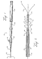
- FIG. 1 is an illustration of a clip device similar to the present invention.
- FIG. 2 is an illustration of a portion of the clip device of fig.1 before the retainers are joined.
- FIG. 3 is an illustration of a portion of the clip device of fig.1 after the retainers are joined.
- the present invention provides a clip device for tissue or the like.
- a clip device similar to the present invention is shown.
- the clip device 10 includes a clip 12 with a proximal end 14 having at least three arms 16 extending from the proximal end. Each arm is preferably inwardly bent at its end 18 to better grasp the tissue. While three arms are preferred, it is contemplated that more than three arms may be used.
- the clip may be made from any suitable resilient material such as stainless steel, nitinol, plastic, and the like.
- the arms may have a cross-sectional shape that is round, square, triangular, pie-shaped, truncated cone, and the like.
- the proximal end 14 has a first retainer 20 attached to the arms.
- the first retainer is permanently attached to the arms.
- the retainer is provided with a shape that will complement a shape provided on a second retainer so that the first and second retainers will matingly join with each other.
- the first retainer has a first end 22 and a second end 24 with a notch 26 disposed between the first end and the second end.
- the first retainer at the first end has a first diameter 23 and at the second end 24, the retainer is in the shape of a half-cylinder having a flat top surface 25. As will be explained in more detail below, this shape advantageously provides secure mating with a complementary second retainer without increasing the diameter beyond that of the first end of the retainer.
- the clip device 10 also has an outer sheath 30 (or introducing tube) having an inner diameter that receives an inner sheath 40.
- the inner sheath can be advanced and retracted independently of the outer sheath.
- the inner sheath has an inner diameter that receives an operating wire 50 with a distal end 52.
- the outer sheath is attached at its proximal end to a forward handle portion 80.
- the inner sheath extends through the forward handle portion 80 and is attached at its proximal end to a middle handle portion 82, which is disposed proximally of the forward handle portion.
- the operating wire extends through the forward and middle handle portions, and is attached at its proximal end to a rearward handle portion 84, which telescopically extends over the proximal portion of the middle handle portion.
- longitudinal movement of the operating wire and the inner and outer sheaths with respect to each other is controlled by longitudinal manipulation of the forward, middle and rearward handles portions with respect to each other.
- the forward handle portion includes a flushing port 86.
- the flushing port can comprise a standard male or female luer fitting, or any other valve mechanism that permits the injection of fluid therethrough.
- the flushing port is in fluid communication with the interior volume of the forward handle portion, which in turn is in fluid communication with a cavity or gap 88 that is disposed between the inner and outer sheaths. Accordingly, any fluid injected through the flushing port will necessarily enter the cavity between the inner and outer sheaths, and will subsequently exit the cavity near the distal end 90 of the outer sheath (see FIG. 2 ). In other words, the fluid injected through the flushing port will exit the clip device near the clip.
- the cavity can be disposed inside the inner sheath, or either the inner or the outer sheath can comprise a lumen disposed therein through which fluid can be passed along the length thereof.
- the flushing port could be alternatively located on either of the middle or rearward handle portions, or on a portion of the outer sheath distally of any of the handle portions.
- a second retainer 60 is attached to the distal end of the operating wire.
- the second retainer is complementary to the first retainer so that the first and second retainers can be matingly joined.
- the second retainer has a first end 62 and a second end 64 with a notch 66 disposed between the first end and the second end.
- the second retainer at the first end has a first diameter 63 and at the second end 64, the retainer is in the shape of a half-cylinder having a flat surface 65.
- the first diameter of the second retainer is substantially identical to the first diameter of the first retainer.
- the first and second retainers are joined with each by locating the flat surface 25 of the first retainer within the notch 66 of the second retainer and by locating the flat surface 65 of the second retainer within the notch 26 of the first retainer. Because the second end of each of the first and second retainers are each about one-half the diameter of the first diameter of their respective retainers, when joined, the first and second retainers form a substantially continuous cylinder shape having substantially the same diameter from the first end of the second retainer to the first end of the first retainer.
- a sliding ring 70' is provided, with an inner diameter slightly larger than the first diameter of the first retainer and the second retainer (Note that sliding ring 70 as illustrated has an inner diameter smaller than the first diameter of the first retainer).
- the inner diameter of the sliding ring is such that the sliding ring can slide over the retainers yet hold and maintain them in a joined position.
- the sliding ring can slide over the first and second retainers to hold them in a mating position.
- the sliding ring can slide toward the ends of the arms of the clip causing the arms to move to a closed position.
- the sliding ring 70 has an inner diameter smaller than the first diameter on the first retainer.
- the sliding ring is not removable from the clip. Accordingly, the sliding ring can be located adjacent the proximal end of the clip so that the arms are in an open position. The sliding ring can then be moved to a position toward the ends of the arms to close them.
- the operation of the invention will be described.
- the outer sheath of the clip device is retracted to expose the inner sheath, the operating wire, and the second retainer.
- a clip according to the present invention is provided and the first retainer is matingly joined with the second retainer.
- the sliding ring is pushed over the first and second retainers so that they are maintained in a joined position.
- the outer sheath is pushed toward the distal end of the inner sheath and beyond the clip causing the arms of the clip to close.
- the outer tube is introduced into a body cavity via a channel of an endoscope that has been previously inserted into the body cavity. While the body cavity is observed via the endoscope, the distal end portion of the outer sheath is guided to a part to be treated.
- a fluid such as saline is injected through the flushing port on the forward handle portion.
- the saline enters the cavity or gap between the inner and outer sheaths, and exits the distal end of the outer sheath.
- the saline floods the area so as to flush any blood or bodily fluids away from the part to be treated.
- the injection of saline is continued and/or repeated as necessary during the following steps so as to keep the area free of blood and other bodily fluids.
- a vacuum is applied to the flushing port so as to create suction within the cavity or gap between the inner and outer sheaths.
- This suction can be used to remove blood or other bodily fluids from the area surrounding the part to be treated.
- the outer sheath is pulled toward the proximal end (i.e., retracted) to expose the clip and the distal end portion of the inner sheath.
- the inner sheath is then advanced toward the clip causing the sliding ring to slide toward the arms of the clip causing the arms to close.
- the inner sheath is then retracted and when the distal end of the inner sheath passes the first and second retainers, they detach and release from each other and the clip is left inside the body cavity, holding the tissue.
- the clip operating device is removed from the channel of the endoscope. The operation of the illustrated clip device and system will be described.
- the outer sheath of the clip device is retracted to expose the inner sheath, the operating wire, and the second retainer.
- a clip is provided and the first retainer is matingly joined with the second retainer.
- the sliding ring cannot slide and is pushed toward the distal end unit so that the first and second retainers are maintained in a joined position.
- the outer sheath is pushed toward the distal end of the inner sheath and beyond to the clip causing the arms of the clip to close.
- the outer tube is introduced into a body cavity via a channel of an endoscope that has been previously inserted into the body cavity. While the body cavity is observed via the endoscope, the distal end portion of the outer sheath is guided to a part to be treated.
- the outer sheath is pulled toward the proximal end side to expose the clip and the distal end portion of the inner sheath.
- the inner sheath is then advanced toward the clip causing the sliding ring to slide toward the arms of the clip causing the arms to close.
- the inner sheath is then retracted and when the distal end of the inner sheath passes the first and second retainers, they detach and release from each other and the clip is left inside the body cavity, holding the tissue. After disengaging the retainers, the clip operating device is removed from the channel of the endoscope.
Landscapes
- Health & Medical Sciences (AREA)
- Surgery (AREA)
- Life Sciences & Earth Sciences (AREA)
- Heart & Thoracic Surgery (AREA)
- Molecular Biology (AREA)
- Vascular Medicine (AREA)
- Engineering & Computer Science (AREA)
- Biomedical Technology (AREA)
- Reproductive Health (AREA)
- Medical Informatics (AREA)
- Nuclear Medicine, Radiotherapy & Molecular Imaging (AREA)
- Animal Behavior & Ethology (AREA)
- General Health & Medical Sciences (AREA)
- Public Health (AREA)
- Veterinary Medicine (AREA)
- Surgical Instruments (AREA)
- Gripping Jigs, Holding Jigs, And Positioning Jigs (AREA)
Claims (7)
- Dispositif de pince (10) destiné à l'utilisation dans des procédures médicales endoscopiques, comprenant :a) un premier dispositif de retenue (20) ayant une portion proximale (22) en forme de segment de cercle en section transversale, ayant une portion distale (24) de forme cylindrique de même diamètre, et ayant une encoche (26) en forme de segment du même cercle en section transversale, pratiquée entre la portion proximale et la portion distale ;b) une pluralité de bras (16) ayant chacun une extrémité proximale et une extrémité distale (18), l'extrémité proximale de chacun des bras étant réunie au premier dispositif de retenue (20) et s'étendant distalement depuis celui-ci, chacun desdits bras étant formé d'un matériau élastique et formé de manière à ce que les extrémités distales aient tendance à s'écarter les unes des autres lorsque ledit dispositif de pince est dans une position ouverte et à se trouver adjacentes les unes aux autres lorsque ledit dispositif de pince est dans une position fermée ;c) une bague coulissante (70') disposée autour de la pluralité de bras, ladite bague coulissante étant déplaçable entre une première position lorsque ledit dispositif de pince est dans la position ouverte et une deuxième position lorsque ledit dispositif de pince est dans la position fermée, ladite bague coulissante étant configurée de manière à amener les extrémités distales (18) desdits bras de manière adjacente les unes aux autres dans la deuxième position, le premier dispositif de retenue (20) étant disposé dans la bague coulissante (70') lorsque la bague coulissante est dans la première position, et étant disposé à proximité de la bague coulissante lorsque la bague coulissante est dans la deuxième position, et la bague coulissante (70') comprenant une portion proximale et une portion distale, la portion proximale ayant une première section transversale tubulaire définissant une surface intérieure qui est configurée de manière à s'engager par coulissement avec une surface extérieure du premier dispositif de retenue (20), et la portion distale ayant une deuxième section transversale tubulaire qui est configurée de manière à s'engager par coulissement avec une surface extérieure de chacun desdits bras (16), la deuxième section transversale tubulaire étant plus petite que la première section transversale tubulaire pour empêcher que ladite bague coulissante ne soit enlevée de l'extrémité proximale du dispositif de pince.
- Dispositif de pince (10) selon la revendication 1, dans lequel l'extrémité distale de chacun desdits bras (16) comprend une portion de pointe recourbée vers l'intérieur (18).
- Dispositif de pince (10) selon l'une quelconque des revendications précédentes, dans lequel ledit dispositif de pince comprend trois bras équidistants (16), chacun desdits bras étant recourbé le long d'une portion entre l'extrémité distale et l'extrémité proximale.
- Système de pince comprenant le dispositif de pince (10) selon l'une quelconque des revendications précédentes en combinaison avec un système de distribution, dans lequel le système de distribution comprend un fil opérationnel (50), une gaine intérieure (40), une gaine extérieure (30) et une poignée (80), le fil opérationnel étant disposé de manière coulissante dans la gaine intérieure et étant attaché à un deuxième dispositif de retenue (60) de forme complémentaire dudit premier dispositif de retenue (20), la gaine intérieure étant disposée de manière coulissante dans la gaine extérieure et étant configurée de manière à s'engager avec une extrémité proximale de la bague coulissante (70'), et la gaine extérieure étant configurée de manière à enfermer le dispositif de pince lorsque le dispositif de pince est dans la position fermée.
- Système selon la revendication 4, dans lequel la poignée (80) comporte un orifice de rinçage (86) qui est en communication fluidique avec un volume intérieur du système de distribution.
- Système selon la revendication 5, dans lequel l'orifice de rinçage (86) est en communication fluidique avec une cavité entre la gaine intérieure (40) et la gaine extérieure (30), l'orifice de rinçage étant configuré de manière à permettre l'entrée de fluide depuis les environs du dispositif de pince.
- Système selon la revendication 5 ou 6, dans lequel l'orifice de rinçage (86) comprend un connecteur de verrouillage Luer standard.
Applications Claiming Priority (5)
| Application Number | Priority Date | Filing Date | Title |
|---|---|---|---|
| US37250402P | 2002-04-15 | 2002-04-15 | |
| US372504P | 2002-04-15 | ||
| US42452402P | 2002-11-07 | 2002-11-07 | |
| US424524P | 2002-11-07 | ||
| PCT/US2003/011820 WO2003088850A1 (fr) | 2002-04-15 | 2003-04-15 | Dispositif de pince hemostatique |
Publications (2)
| Publication Number | Publication Date |
|---|---|
| EP1494598A1 EP1494598A1 (fr) | 2005-01-12 |
| EP1494598B1 true EP1494598B1 (fr) | 2009-01-07 |
Family
ID=29254490
Family Applications (2)
| Application Number | Title | Priority Date | Filing Date |
|---|---|---|---|
| EP03728398A Withdrawn EP1494599A1 (fr) | 2002-04-15 | 2003-04-15 | Dispositif de pose d'agrafes avec moyen de rin age |
| EP03719796A Expired - Lifetime EP1494598B1 (fr) | 2002-04-15 | 2003-04-15 | Dispositif de pince hemostatique |
Family Applications Before (1)
| Application Number | Title | Priority Date | Filing Date |
|---|---|---|---|
| EP03728398A Withdrawn EP1494599A1 (fr) | 2002-04-15 | 2003-04-15 | Dispositif de pose d'agrafes avec moyen de rin age |
Country Status (10)
| Country | Link |
|---|---|
| US (1) | US7122041B2 (fr) |
| EP (2) | EP1494599A1 (fr) |
| JP (2) | JP4362069B2 (fr) |
| AT (1) | ATE419796T1 (fr) |
| AU (2) | AU2003223655B2 (fr) |
| CA (2) | CA2481738C (fr) |
| DE (1) | DE60325711D1 (fr) |
| DK (1) | DK1494598T3 (fr) |
| ES (1) | ES2321181T3 (fr) |
| WO (2) | WO2003088850A1 (fr) |
Families Citing this family (21)
| Publication number | Priority date | Publication date | Assignee | Title |
|---|---|---|---|---|
| US7837631B2 (en) * | 2003-03-14 | 2010-11-23 | Boston Scientific Scimed Inc. | Biopsy forceps with removable jaw segments |
| US7758594B2 (en) * | 2005-05-20 | 2010-07-20 | Neotract, Inc. | Devices, systems and methods for treating benign prostatic hyperplasia and other conditions |
| US10195014B2 (en) | 2005-05-20 | 2019-02-05 | Neotract, Inc. | Devices, systems and methods for treating benign prostatic hyperplasia and other conditions |
| AU2007225266B2 (en) * | 2006-03-10 | 2013-06-06 | Cook Medical Technologies Llc | A clip device and a protective cap for drawing the target tissue into it before the clip is deployed |
| EP2020925B1 (fr) * | 2006-06-01 | 2013-07-10 | Cook Medical Technologies LLC | Mécanismes de libération d'un dispositif d'agrafe |
| US8945153B2 (en) * | 2006-06-05 | 2015-02-03 | Cook Medical Technologies Llc | Endoscopic apparatus having a clip device |
| US8425412B2 (en) * | 2006-07-14 | 2013-04-23 | Cook Medical Technologies Llc | Papilla spreader |
| US8152822B2 (en) * | 2006-12-05 | 2012-04-10 | Cook Medical Technologies Llc | Combination therapy hemostatic clip |
| US8133242B1 (en) | 2007-04-27 | 2012-03-13 | Q-Tech Medical Incorporated | Image-guided extraluminal occlusion |
| ITMC20080082A1 (it) * | 2008-05-19 | 2009-11-20 | Vincenzo Magliani | Pinza per laminectomia. |
| DE102008031387A1 (de) | 2008-07-02 | 2010-01-07 | Medi-Globe Gmbh | Medizinischer Clip |
| DE102009036365A1 (de) | 2009-08-06 | 2011-02-10 | Norbert Lemke | Chirurgische Klammer sowie Vorrichtung zum intrakorporalen Einbringen der chirurgischen Klammer |
| US8211121B1 (en) | 2010-03-06 | 2012-07-03 | Q-Tech Medical Incorporated | Methods and apparatus for image-guided extraluminal occlusion using clamping jaws |
| US9044240B2 (en) | 2010-03-10 | 2015-06-02 | Boston Scientific Scimed, Inc. | Hemostasis clip |
| AU2011237745A1 (en) | 2010-04-08 | 2012-10-25 | Cook Medical Technologies Llc | Marker clip device |
| US8764774B2 (en) | 2010-11-09 | 2014-07-01 | Cook Medical Technologies Llc | Clip system having tether segments for closure |
| CN105310738B (zh) * | 2014-12-24 | 2017-12-26 | 石益海 | 一种三瓣式可脱落夹持装置 |
| JP6595232B2 (ja) * | 2015-07-02 | 2019-10-23 | ソニー・オリンパスメディカルソリューションズ株式会社 | 内視鏡用撮像装置、内視鏡装置、及び内視鏡用ケーブル |
| WO2017059598A1 (fr) * | 2015-10-10 | 2017-04-13 | 杭州安杰思医学科技有限公司 | Pince hémostatique pour nettoyage des suintements sanguins sur des sites hémorragiques |
| CN110960285A (zh) * | 2020-01-15 | 2020-04-07 | 付志刚 | 一种带止血功能血管鞘组 |
| WO2023028250A1 (fr) | 2021-08-25 | 2023-03-02 | GastroLogic LLC | Appareil et procédés d'attache endoscopique |
Family Cites Families (114)
| Publication number | Priority date | Publication date | Assignee | Title |
|---|---|---|---|---|
| US45909A (en) * | 1865-01-17 | Improvement in combs | ||
| US62130A (en) * | 1867-02-19 | Improvement in the manufacture of oaebonate of lead | ||
| US55750A (en) * | 1866-06-19 | Improvement | ||
| US32462A (en) * | 1861-06-04 | Improvement in harrows | ||
| US49497A (en) * | 1865-08-22 | Improvement in harvesting-machines | ||
| US173805A (en) * | 1876-02-22 | Improvement in grates | ||
| US69592A (en) * | 1867-10-08 | Improvement in brick machines | ||
| US138083A (en) * | 1873-04-22 | Improvement in invalid-bedsteads | ||
| US138085A (en) * | 1873-04-22 | Improvement in cultivators | ||
| US69593A (en) * | 1867-10-08 | Improvement in straw-cutters | ||
| US151916A (en) * | 1874-06-09 | Improvement in snow-plows | ||
| US36720A (en) * | 1862-10-21 | Improvement in vapor-baths | ||
| US133178A (en) * | 1872-11-19 | Improvement in imdia-ink slabs | ||
| US128667A (en) * | 1872-07-02 | Improvement in lumber-wagons | ||
| US943263A (en) | 1909-05-06 | 1909-12-14 | Ernest Moraweck | Surgical forceps. |
| US1510416A (en) | 1922-04-15 | 1924-09-30 | Pietz Frederick | Forceps |
| US1578800A (en) * | 1926-01-19 | 1926-03-30 | Carl F Brandenberger | Grabbing tool |
| US2113246A (en) | 1937-05-17 | 1938-04-05 | Wappler Frederick Charles | Endoscopic forceps |
| US2384697A (en) | 1944-10-18 | 1945-09-11 | Riccardi Peter | Umbilical clip |
| US2968041A (en) | 1958-09-25 | 1961-01-17 | John F Skold | Applicator for surgical clamps |
| US3378010A (en) | 1965-07-28 | 1968-04-16 | Coldling | Surgical clip with means for releasing the clamping pressure |
| US3518993A (en) | 1967-05-01 | 1970-07-07 | American Hospital Supply Corp | Surgical clip applicator |
| US3616497A (en) | 1970-06-24 | 1971-11-02 | Vincent J Esposito Jr | Integral clamping instruments for medical and surgical applications |
| US3777538A (en) | 1972-03-15 | 1973-12-11 | Weck & Co Edward | Surgical clip applicator |
| DE2330182A1 (de) | 1973-06-14 | 1975-01-02 | Wolf Gmbh Richard | Zange zum setzen von tantal-clips |
| US3882854A (en) | 1973-08-23 | 1975-05-13 | Research Corp | Surgical clip and applicator |
| DE2342490A1 (de) * | 1973-08-23 | 1975-03-06 | Praemeta | Abschnuervorrichtung zur durchfuehrung von staueffekten an koerperteilen |
| JPS5320957Y2 (fr) * | 1973-11-14 | 1978-06-01 | ||
| JPS552966Y2 (fr) | 1974-02-08 | 1980-01-24 | ||
| US4046149A (en) | 1975-01-31 | 1977-09-06 | Olympus Optical Co., Ltd. | Instrument for removing a foreign substance from the body cavity of human being |
| US4169476A (en) | 1977-08-12 | 1979-10-02 | Wolf Medical Instruments Corporation | Applicator for surgical clip |
| US4215871A (en) | 1979-03-05 | 1980-08-05 | Vargus Ltd. | Hand held collet |
| AR218795A1 (es) | 1979-12-11 | 1980-06-30 | Derechinsky V | Instrumento porta-clips para el "clipado" de vasos sanguineos |
| US4446865A (en) | 1981-03-16 | 1984-05-08 | Ethicon, Inc. | Plastic ligating clips |
| US4394864A (en) | 1981-04-15 | 1983-07-26 | Jeffrey Sandhaus | Apparatus and method for effecting occlusion of the vas deferens |
| US4394861A (en) | 1981-05-11 | 1983-07-26 | Sciortino Lawrence A | Outside air breathing supply system |
| US4496090A (en) | 1982-03-10 | 1985-01-29 | Crevier Paul H | Surgical stapler |
| US4485817A (en) | 1982-05-28 | 1984-12-04 | United States Surgical Corporation | Surgical stapler apparatus with flexible shaft |
| US4512345A (en) | 1982-09-30 | 1985-04-23 | United States Surgical Corporation | Surgical clip applying apparatus, and clips and clip train for use therein |
| US4492232A (en) | 1982-09-30 | 1985-01-08 | United States Surgical Corporation | Surgical clip applying apparatus having fixed jaws |
| GB8422863D0 (en) | 1984-09-11 | 1984-10-17 | Univ London | Sewing machine |
| US4821721A (en) | 1985-01-14 | 1989-04-18 | Thomas J. Fogarty | Apparatus and method for applying hemostatic scalp clips |
| US4706668A (en) | 1985-09-16 | 1987-11-17 | B & B Tools | Aneurysm clip pliers |
| DE3533423A1 (de) | 1985-09-19 | 1987-03-26 | Wolf Gmbh Richard | Applikator-zangeneinsatz fuer chirurgische handhabe zur anwendung in der endoskopie |
| US4681107A (en) | 1985-12-31 | 1987-07-21 | Kees Surgical Specialty Co. | Device for holding an aneurysm clip |
| US4714075A (en) | 1986-02-10 | 1987-12-22 | Welch Allyn, Inc. | Biopsy channel for endoscope |
| US4796627A (en) | 1986-08-26 | 1989-01-10 | Tucker Wilson H | Clip applicator and spreadable clips for use therein |
| US4735194C1 (en) | 1987-01-13 | 2001-05-08 | Dept Of Veterans Affairs The U | Flexile endoscopic ligating instrument |
| US5366459A (en) | 1987-05-14 | 1994-11-22 | Inbae Yoon | Surgical clip and clip application procedures |
| US5100418A (en) | 1987-05-14 | 1992-03-31 | Inbae Yoon | Suture tie device system and applicator therefor |
| US4945920A (en) | 1988-03-28 | 1990-08-07 | Cordis Corporation | Torqueable and formable biopsy forceps |
| US4835824A (en) | 1988-04-13 | 1989-06-06 | Durham Vaughn L | Medical clamp |
| US4887612A (en) | 1988-04-27 | 1989-12-19 | Esco Precision, Inc. | Endoscopic biopsy forceps |
| US4971067A (en) | 1988-05-05 | 1990-11-20 | Lee Bolduc | Biopsy instrument with a disposable cutting blade |
| US4880015A (en) | 1988-06-03 | 1989-11-14 | Nierman David M | Biopsy forceps |
| US5486185A (en) | 1989-01-30 | 1996-01-23 | Dexide, Inc. | Surgical apparatus |
| US4983176A (en) | 1989-03-06 | 1991-01-08 | University Of New Mexico | Deformable plastic surgical clip |
| US5015249A (en) | 1989-12-26 | 1991-05-14 | Nakao Naomi L | Endoscopic stapling device and method |
| US5049153A (en) | 1989-12-26 | 1991-09-17 | Nakao Naomi L | Endoscopic stapling device and method |
| US5222961A (en) | 1989-12-26 | 1993-06-29 | Naomi Nakao | Endoscopic stapling device and related staple |
| US5156609A (en) | 1989-12-26 | 1992-10-20 | Nakao Naomi L | Endoscopic stapling device and method |
| US5062848A (en) | 1990-03-07 | 1991-11-05 | Frazee John G | Hemostatic clip and applicator therefor |
| USRE36720E (en) | 1990-12-13 | 2000-05-30 | United States Surgical Corporation | Apparatus and method for applying latchless surgical clips |
| US5366458A (en) | 1990-12-13 | 1994-11-22 | United States Surgical Corporation | Latchless surgical clip |
| US5112343A (en) | 1991-04-05 | 1992-05-12 | Edward Weck Incorporated | Endoscopic clip appliers |
| US5242456A (en) | 1991-11-21 | 1993-09-07 | Kensey Nash Corporation | Apparatus and methods for clamping tissue and reflecting the same |
| CA2088883A1 (fr) | 1992-02-13 | 1993-08-14 | David T. Green | Instrument endoscopique de ligature |
| US5304183A (en) | 1992-03-23 | 1994-04-19 | Laparomed Corporation | Tethered clamp retractor |
| CA2094463A1 (fr) | 1992-04-28 | 1993-10-29 | Claude Vidal | Pinces pour vaisseaux |
| CN1049172C (zh) * | 1992-06-19 | 2000-02-09 | 爱德华·波里斯·施洛 | 一种可调整夹紧装置 |
| US5342373A (en) | 1992-09-14 | 1994-08-30 | Ethicon, Inc. | Sterile clips and instrument for their placement |
| US5300081A (en) | 1992-10-09 | 1994-04-05 | United States Surgical Corporation | Surgical clip applier having clip advancement control |
| US5464416A (en) | 1992-11-10 | 1995-11-07 | Ethicon, Inc. | Ligating clip |
| US5569274A (en) | 1993-02-22 | 1996-10-29 | Heartport, Inc. | Endoscopic vascular clamping system and method |
| JPH071905U (ja) * | 1993-06-15 | 1995-01-13 | オリンパス光学工業株式会社 | クリップ装置 |
| US6155968A (en) | 1998-07-23 | 2000-12-05 | Wilk; Peter J. | Method and device for improving cardiac function |
| JP3523712B2 (ja) * | 1995-04-13 | 2004-04-26 | オリンパス株式会社 | 結紮装置 |
| JPH08126648A (ja) * | 1994-11-02 | 1996-05-21 | Olympus Optical Co Ltd | 内視鏡用処置具 |
| WO1996014020A1 (fr) | 1994-11-02 | 1996-05-17 | Olympus Optical Co. Ltd. | Instrument fonctionnant avec un endoscope |
| US5514148A (en) | 1994-11-04 | 1996-05-07 | Smith, Iii; Ray C. | Surgical clamp and method of use |
| US5695504A (en) | 1995-02-24 | 1997-12-09 | Heartport, Inc. | Devices and methods for performing a vascular anastomosis |
| US6464710B1 (en) | 1995-03-06 | 2002-10-15 | Cook Urological Incorporated | Releasable, surgical clamp |
| US5634932A (en) | 1995-10-10 | 1997-06-03 | Industrial & Scientific Designs, Ltd. | Cantilever aneurysm clip system |
| US5700271A (en) | 1995-10-20 | 1997-12-23 | United States Surgical Corporation | Apparatus for applying surgical clips |
| JP3776529B2 (ja) * | 1996-02-29 | 2006-05-17 | オリンパス株式会社 | クリップ装置 |
| DE69736174T2 (de) | 1996-04-19 | 2007-05-16 | Applied Medical Resources Corp., Laguna Hills | Vorrichtung zum anbringen von halteklammern |
| US5782747A (en) | 1996-04-22 | 1998-07-21 | Zimmon Science Corporation | Spring based multi-purpose medical instrument |
| DE29616632U1 (de) | 1996-09-24 | 1996-11-28 | Aesculap Ag, 78532 Tuttlingen | Chirurgisches Anlegegerät für U-förmige Clipse |
| US5733329A (en) | 1996-12-30 | 1998-03-31 | Target Therapeutics, Inc. | Vaso-occlusive coil with conical end |
| US6001110A (en) | 1997-06-20 | 1999-12-14 | Boston Scientific Corporation | Hemostatic clips |
| US6167605B1 (en) | 1997-09-12 | 2001-01-02 | Advanced Cardiovascular Systems, Inc. | Collet type crimping tool |
| GB9722203D0 (en) * | 1997-10-21 | 1997-12-17 | Univ London | Surgical clip |
| US5989268A (en) | 1997-10-28 | 1999-11-23 | Boston Scientific Corporation | Endoscopic hemostatic clipping device |
| DE19752331C1 (de) | 1997-11-26 | 1999-09-30 | Aesculap Ag & Co Kg | Magazin für ein chirurgisches Clipanlegegerät |
| WO2000015144A1 (fr) | 1998-06-10 | 2000-03-23 | Advanced Bypass Technologies, Inc. | Systemes de traitement de l'anevrisme de l'aorte |
| DE29811510U1 (de) | 1998-06-27 | 1998-10-08 | Tenckhoff, Dirk, 36100 Petersberg | Einrichtung zur Handhabung von Clips, insbesondere für mikrochirurgische Eingriffe |
| US5980534A (en) * | 1998-10-07 | 1999-11-09 | Gimpelson; Richard J. | Cervical clamp |
| AU6288799A (en) * | 1998-10-09 | 2000-05-01 | Cook Incorporated | Vasoocclusion coil device having a core therein |
| US6350269B1 (en) | 1999-03-01 | 2002-02-26 | Apollo Camera, L.L.C. | Ligation clip and clip applier |
| JP2000254143A (ja) * | 1999-03-08 | 2000-09-19 | Asahi Optical Co Ltd | 内視鏡用止血クリップ装置 |
| US6267776B1 (en) | 1999-05-03 | 2001-07-31 | O'connell Paul T. | Vena cava filter and method for treating pulmonary embolism |
| US6911032B2 (en) | 1999-11-18 | 2005-06-28 | Scimed Life Systems, Inc. | Apparatus and method for compressing body tissue |
| US6428548B1 (en) | 1999-11-18 | 2002-08-06 | Russell F. Durgin | Apparatus and method for compressing body tissue |
| AU2001249308A1 (en) | 2000-03-24 | 2001-10-15 | Johns Hopkins University | Peritoneal cavity device and method |
| JP4472217B2 (ja) | 2000-10-16 | 2010-06-02 | オリンパス株式会社 | 生体組織のクリップ装置 |
| JP4097924B2 (ja) | 2001-02-05 | 2008-06-11 | オリンパス株式会社 | 生体組織のクリップ装置 |
| JP2002224124A (ja) | 2001-02-06 | 2002-08-13 | Olympus Optical Co Ltd | 結紮装置 |
| JP4059656B2 (ja) | 2001-03-07 | 2008-03-12 | オリンパス株式会社 | 生体組織のクリップ装置 |
| JP4827304B2 (ja) | 2001-03-14 | 2011-11-30 | オリンパス株式会社 | 生体組織のクリップ装置 |
| JP4698864B2 (ja) | 2001-03-22 | 2011-06-08 | オリンパス株式会社 | 多機能外科用器具 |
| JP4578708B2 (ja) | 2001-03-26 | 2010-11-10 | オリンパス株式会社 | 生体組織のクリップ装置 |
| US7125421B2 (en) | 2001-08-31 | 2006-10-24 | Mitral Interventions, Inc. | Method and apparatus for valve repair |
| US7094245B2 (en) | 2001-10-05 | 2006-08-22 | Scimed Life Systems, Inc. | Device and method for through the scope endoscopic hemostatic clipping |
| US7727247B2 (en) | 2002-08-21 | 2010-06-01 | Olympus Corporation | Living tissue ligation device |
-
2003
- 2003-04-15 EP EP03728398A patent/EP1494599A1/fr not_active Withdrawn
- 2003-04-15 AU AU2003223655A patent/AU2003223655B2/en not_active Ceased
- 2003-04-15 CA CA002481738A patent/CA2481738C/fr not_active Expired - Fee Related
- 2003-04-15 EP EP03719796A patent/EP1494598B1/fr not_active Expired - Lifetime
- 2003-04-15 WO PCT/US2003/011820 patent/WO2003088850A1/fr active Application Filing
- 2003-04-15 JP JP2003585605A patent/JP4362069B2/ja not_active Expired - Lifetime
- 2003-04-15 US US10/414,417 patent/US7122041B2/en not_active Expired - Lifetime
- 2003-04-15 WO PCT/US2003/011496 patent/WO2003088849A1/fr active Application Filing
- 2003-04-15 JP JP2003585604A patent/JP2005522298A/ja active Pending
- 2003-04-15 AT AT03719796T patent/ATE419796T1/de not_active IP Right Cessation
- 2003-04-15 DE DE60325711T patent/DE60325711D1/de not_active Expired - Lifetime
- 2003-04-15 AU AU2003234092A patent/AU2003234092B2/en not_active Ceased
- 2003-04-15 ES ES03719796T patent/ES2321181T3/es not_active Expired - Lifetime
- 2003-04-15 DK DK03719796T patent/DK1494598T3/da active
- 2003-04-15 CA CA002481745A patent/CA2481745C/fr not_active Expired - Fee Related
Also Published As
| Publication number | Publication date |
|---|---|
| DK1494598T3 (da) | 2009-04-14 |
| WO2003088849A1 (fr) | 2003-10-30 |
| ATE419796T1 (de) | 2009-01-15 |
| US7122041B2 (en) | 2006-10-17 |
| DE60325711D1 (de) | 2009-02-26 |
| AU2003234092B2 (en) | 2009-06-11 |
| CA2481738C (fr) | 2009-11-17 |
| AU2003223655A1 (en) | 2003-11-03 |
| CA2481745A1 (fr) | 2003-10-30 |
| AU2003223655B2 (en) | 2009-06-25 |
| AU2003234092A1 (en) | 2003-11-03 |
| JP2005522299A (ja) | 2005-07-28 |
| EP1494598A1 (fr) | 2005-01-12 |
| JP4362069B2 (ja) | 2009-11-11 |
| JP2005522298A (ja) | 2005-07-28 |
| EP1494599A1 (fr) | 2005-01-12 |
| CA2481738A1 (fr) | 2003-10-30 |
| WO2003088850A1 (fr) | 2003-10-30 |
| ES2321181T3 (es) | 2009-06-03 |
| US20040092978A1 (en) | 2004-05-13 |
| CA2481745C (fr) | 2008-01-08 |
Similar Documents
| Publication | Publication Date | Title |
|---|---|---|
| CA2601234C (fr) | Dispositif multi-agrafe | |
| EP1494598B1 (fr) | Dispositif de pince hemostatique | |
| EP2034908B1 (fr) | Clip aspirant | |
| JP5204100B2 (ja) | クリップ器具用解除機構 | |
| EP2101653B1 (fr) | Pince hémostatique de thérapie combinée | |
| US20120083804A1 (en) | Marker clip device |
Legal Events
| Date | Code | Title | Description |
|---|---|---|---|
| PUAI | Public reference made under article 153(3) epc to a published international application that has entered the european phase |
Free format text: ORIGINAL CODE: 0009012 |
|
| 17P | Request for examination filed |
Effective date: 20041025 |
|
| AK | Designated contracting states |
Kind code of ref document: A1 Designated state(s): AT BE BG CH CY CZ DE DK EE ES FI FR GB GR HU IE IT LI LU MC NL PT RO SE SI SK TR |
|
| AX | Request for extension of the european patent |
Extension state: AL LT LV MK |
|
| 17Q | First examination report despatched |
Effective date: 20050216 |
|
| GRAP | Despatch of communication of intention to grant a patent |
Free format text: ORIGINAL CODE: EPIDOSNIGR1 |
|
| GRAS | Grant fee paid |
Free format text: ORIGINAL CODE: EPIDOSNIGR3 |
|
| GRAA | (expected) grant |
Free format text: ORIGINAL CODE: 0009210 |
|
| AK | Designated contracting states |
Kind code of ref document: B1 Designated state(s): AT BE BG CH CY CZ DE DK EE ES FI FR GB GR HU IE IT LI LU MC NL PT RO SE SI SK TR |
|
| REG | Reference to a national code |
Ref country code: GB Ref legal event code: FG4D |
|
| REG | Reference to a national code |
Ref country code: CH Ref legal event code: EP |
|
| REG | Reference to a national code |
Ref country code: IE Ref legal event code: FG4D |
|
| REF | Corresponds to: |
Ref document number: 60325711 Country of ref document: DE Date of ref document: 20090226 Kind code of ref document: P |
|
| REG | Reference to a national code |
Ref country code: DK Ref legal event code: T3 |
|
| PG25 | Lapsed in a contracting state [announced via postgrant information from national office to epo] |
Ref country code: SI Free format text: LAPSE BECAUSE OF FAILURE TO SUBMIT A TRANSLATION OF THE DESCRIPTION OR TO PAY THE FEE WITHIN THE PRESCRIBED TIME-LIMIT Effective date: 20090107 Ref country code: NL Free format text: LAPSE BECAUSE OF FAILURE TO SUBMIT A TRANSLATION OF THE DESCRIPTION OR TO PAY THE FEE WITHIN THE PRESCRIBED TIME-LIMIT Effective date: 20090107 |
|
| NLV1 | Nl: lapsed or annulled due to failure to fulfill the requirements of art. 29p and 29m of the patents act | ||
| REG | Reference to a national code |
Ref country code: ES Ref legal event code: FG2A Ref document number: 2321181 Country of ref document: ES Kind code of ref document: T3 |
|
| PG25 | Lapsed in a contracting state [announced via postgrant information from national office to epo] |
Ref country code: FI Free format text: LAPSE BECAUSE OF FAILURE TO SUBMIT A TRANSLATION OF THE DESCRIPTION OR TO PAY THE FEE WITHIN THE PRESCRIBED TIME-LIMIT Effective date: 20090107 |
|
| PG25 | Lapsed in a contracting state [announced via postgrant information from national office to epo] |
Ref country code: AT Free format text: LAPSE BECAUSE OF FAILURE TO SUBMIT A TRANSLATION OF THE DESCRIPTION OR TO PAY THE FEE WITHIN THE PRESCRIBED TIME-LIMIT Effective date: 20090107 Ref country code: SE Free format text: LAPSE BECAUSE OF FAILURE TO SUBMIT A TRANSLATION OF THE DESCRIPTION OR TO PAY THE FEE WITHIN THE PRESCRIBED TIME-LIMIT Effective date: 20090407 Ref country code: PT Free format text: LAPSE BECAUSE OF FAILURE TO SUBMIT A TRANSLATION OF THE DESCRIPTION OR TO PAY THE FEE WITHIN THE PRESCRIBED TIME-LIMIT Effective date: 20090608 |
|
| PG25 | Lapsed in a contracting state [announced via postgrant information from national office to epo] |
Ref country code: BE Free format text: LAPSE BECAUSE OF FAILURE TO SUBMIT A TRANSLATION OF THE DESCRIPTION OR TO PAY THE FEE WITHIN THE PRESCRIBED TIME-LIMIT Effective date: 20090107 |
|
| PG25 | Lapsed in a contracting state [announced via postgrant information from national office to epo] |
Ref country code: CZ Free format text: LAPSE BECAUSE OF FAILURE TO SUBMIT A TRANSLATION OF THE DESCRIPTION OR TO PAY THE FEE WITHIN THE PRESCRIBED TIME-LIMIT Effective date: 20090107 Ref country code: EE Free format text: LAPSE BECAUSE OF FAILURE TO SUBMIT A TRANSLATION OF THE DESCRIPTION OR TO PAY THE FEE WITHIN THE PRESCRIBED TIME-LIMIT Effective date: 20090107 |
|
| PLBE | No opposition filed within time limit |
Free format text: ORIGINAL CODE: 0009261 |
|
| STAA | Information on the status of an ep patent application or granted ep patent |
Free format text: STATUS: NO OPPOSITION FILED WITHIN TIME LIMIT |
|
| PG25 | Lapsed in a contracting state [announced via postgrant information from national office to epo] |
Ref country code: RO Free format text: LAPSE BECAUSE OF FAILURE TO SUBMIT A TRANSLATION OF THE DESCRIPTION OR TO PAY THE FEE WITHIN THE PRESCRIBED TIME-LIMIT Effective date: 20090107 Ref country code: SK Free format text: LAPSE BECAUSE OF FAILURE TO SUBMIT A TRANSLATION OF THE DESCRIPTION OR TO PAY THE FEE WITHIN THE PRESCRIBED TIME-LIMIT Effective date: 20090107 |
|
| REG | Reference to a national code |
Ref country code: CH Ref legal event code: PL |
|
| 26N | No opposition filed |
Effective date: 20091008 |
|
| PG25 | Lapsed in a contracting state [announced via postgrant information from national office to epo] |
Ref country code: CH Free format text: LAPSE BECAUSE OF NON-PAYMENT OF DUE FEES Effective date: 20090430 Ref country code: BG Free format text: LAPSE BECAUSE OF FAILURE TO SUBMIT A TRANSLATION OF THE DESCRIPTION OR TO PAY THE FEE WITHIN THE PRESCRIBED TIME-LIMIT Effective date: 20090407 Ref country code: LI Free format text: LAPSE BECAUSE OF NON-PAYMENT OF DUE FEES Effective date: 20090430 |
|
| PG25 | Lapsed in a contracting state [announced via postgrant information from national office to epo] |
Ref country code: MC Free format text: LAPSE BECAUSE OF NON-PAYMENT OF DUE FEES Effective date: 20090430 |
|
| PG25 | Lapsed in a contracting state [announced via postgrant information from national office to epo] |
Ref country code: GR Free format text: LAPSE BECAUSE OF FAILURE TO SUBMIT A TRANSLATION OF THE DESCRIPTION OR TO PAY THE FEE WITHIN THE PRESCRIBED TIME-LIMIT Effective date: 20090408 |
|
| PG25 | Lapsed in a contracting state [announced via postgrant information from national office to epo] |
Ref country code: LU Free format text: LAPSE BECAUSE OF NON-PAYMENT OF DUE FEES Effective date: 20090415 |
|
| PG25 | Lapsed in a contracting state [announced via postgrant information from national office to epo] |
Ref country code: HU Free format text: LAPSE BECAUSE OF FAILURE TO SUBMIT A TRANSLATION OF THE DESCRIPTION OR TO PAY THE FEE WITHIN THE PRESCRIBED TIME-LIMIT Effective date: 20090708 |
|
| PG25 | Lapsed in a contracting state [announced via postgrant information from national office to epo] |
Ref country code: TR Free format text: LAPSE BECAUSE OF FAILURE TO SUBMIT A TRANSLATION OF THE DESCRIPTION OR TO PAY THE FEE WITHIN THE PRESCRIBED TIME-LIMIT Effective date: 20090107 |
|
| REG | Reference to a national code |
Ref country code: GB Ref legal event code: 732E Free format text: REGISTERED BETWEEN 20110804 AND 20110810 |
|
| PG25 | Lapsed in a contracting state [announced via postgrant information from national office to epo] |
Ref country code: CY Free format text: LAPSE BECAUSE OF FAILURE TO SUBMIT A TRANSLATION OF THE DESCRIPTION OR TO PAY THE FEE WITHIN THE PRESCRIBED TIME-LIMIT Effective date: 20090107 |
|
| PGFP | Annual fee paid to national office [announced via postgrant information from national office to epo] |
Ref country code: ES Payment date: 20120419 Year of fee payment: 10 |
|
| PGFP | Annual fee paid to national office [announced via postgrant information from national office to epo] |
Ref country code: DK Payment date: 20130325 Year of fee payment: 11 |
|
| PGFP | Annual fee paid to national office [announced via postgrant information from national office to epo] |
Ref country code: IT Payment date: 20130416 Year of fee payment: 11 |
|
| REG | Reference to a national code |
Ref country code: DK Ref legal event code: EBP Effective date: 20140430 |
|
| PG25 | Lapsed in a contracting state [announced via postgrant information from national office to epo] |
Ref country code: IT Free format text: LAPSE BECAUSE OF NON-PAYMENT OF DUE FEES Effective date: 20140415 |
|
| PG25 | Lapsed in a contracting state [announced via postgrant information from national office to epo] |
Ref country code: DK Free format text: LAPSE BECAUSE OF NON-PAYMENT OF DUE FEES Effective date: 20140430 |
|
| REG | Reference to a national code |
Ref country code: ES Ref legal event code: FD2A Effective date: 20150529 |
|
| PG25 | Lapsed in a contracting state [announced via postgrant information from national office to epo] |
Ref country code: ES Free format text: LAPSE BECAUSE OF NON-PAYMENT OF DUE FEES Effective date: 20140416 |
|
| REG | Reference to a national code |
Ref country code: FR Ref legal event code: PLFP Year of fee payment: 14 |
|
| REG | Reference to a national code |
Ref country code: FR Ref legal event code: PLFP Year of fee payment: 15 |
|
| REG | Reference to a national code |
Ref country code: FR Ref legal event code: PLFP Year of fee payment: 16 |
|
| PGFP | Annual fee paid to national office [announced via postgrant information from national office to epo] |
Ref country code: IE Payment date: 20220328 Year of fee payment: 20 Ref country code: GB Payment date: 20220325 Year of fee payment: 20 |
|
| PGFP | Annual fee paid to national office [announced via postgrant information from national office to epo] |
Ref country code: FR Payment date: 20220324 Year of fee payment: 20 |
|
| PGFP | Annual fee paid to national office [announced via postgrant information from national office to epo] |
Ref country code: DE Payment date: 20220318 Year of fee payment: 20 |
|
| REG | Reference to a national code |
Ref country code: DE Ref legal event code: R071 Ref document number: 60325711 Country of ref document: DE |
|
| REG | Reference to a national code |
Ref country code: GB Ref legal event code: PE20 Expiry date: 20230414 |
|
| REG | Reference to a national code |
Ref country code: IE Ref legal event code: MK9A |
|
| PG25 | Lapsed in a contracting state [announced via postgrant information from national office to epo] |
Ref country code: IE Free format text: LAPSE BECAUSE OF EXPIRATION OF PROTECTION Effective date: 20230415 |
|
| PG25 | Lapsed in a contracting state [announced via postgrant information from national office to epo] |
Ref country code: GB Free format text: LAPSE BECAUSE OF EXPIRATION OF PROTECTION Effective date: 20230414 |