EP1493890A1 - Antrieb für einen Flügel eines Fensters oder einer Klappe - Google Patents
Antrieb für einen Flügel eines Fensters oder einer Klappe Download PDFInfo
- Publication number
- EP1493890A1 EP1493890A1 EP04006165A EP04006165A EP1493890A1 EP 1493890 A1 EP1493890 A1 EP 1493890A1 EP 04006165 A EP04006165 A EP 04006165A EP 04006165 A EP04006165 A EP 04006165A EP 1493890 A1 EP1493890 A1 EP 1493890A1
- Authority
- EP
- European Patent Office
- Prior art keywords
- wing
- drive
- output
- differential
- actuator
- Prior art date
- Legal status (The legal status is an assumption and is not a legal conclusion. Google has not performed a legal analysis and makes no representation as to the accuracy of the status listed.)
- Granted
Links
- 230000033001 locomotion Effects 0.000 claims abstract description 10
- 238000000034 method Methods 0.000 description 5
- 230000000694 effects Effects 0.000 description 2
- 230000002441 reversible effect Effects 0.000 description 2
- 230000005540 biological transmission Effects 0.000 description 1
- 238000010586 diagram Methods 0.000 description 1
- 238000006073 displacement reaction Methods 0.000 description 1
- 230000001105 regulatory effect Effects 0.000 description 1
Images

Classifications
-
- E—FIXED CONSTRUCTIONS
- E05—LOCKS; KEYS; WINDOW OR DOOR FITTINGS; SAFES
- E05B—LOCKS; ACCESSORIES THEREFOR; HANDCUFFS
- E05B47/00—Operating or controlling locks or other fastening devices by electric or magnetic means
- E05B47/0001—Operating or controlling locks or other fastening devices by electric or magnetic means with electric actuators; Constructional features thereof
- E05B47/0012—Operating or controlling locks or other fastening devices by electric or magnetic means with electric actuators; Constructional features thereof with rotary electromotors
-
- E—FIXED CONSTRUCTIONS
- E05—LOCKS; KEYS; WINDOW OR DOOR FITTINGS; SAFES
- E05C—BOLTS OR FASTENING DEVICES FOR WINGS, SPECIALLY FOR DOORS OR WINDOWS
- E05C9/00—Arrangements of simultaneously actuated bolts or other securing devices at well-separated positions on the same wing
-
- E—FIXED CONSTRUCTIONS
- E05—LOCKS; KEYS; WINDOW OR DOOR FITTINGS; SAFES
- E05F—DEVICES FOR MOVING WINGS INTO OPEN OR CLOSED POSITION; CHECKS FOR WINGS; WING FITTINGS NOT OTHERWISE PROVIDED FOR, CONCERNED WITH THE FUNCTIONING OF THE WING
- E05F11/00—Man-operated mechanisms for operating wings, including those which also operate the fastening
- E05F11/02—Man-operated mechanisms for operating wings, including those which also operate the fastening for wings in general, e.g. fanlights
- E05F11/04—Man-operated mechanisms for operating wings, including those which also operate the fastening for wings in general, e.g. fanlights with cords, chains or cables
- E05F11/06—Man-operated mechanisms for operating wings, including those which also operate the fastening for wings in general, e.g. fanlights with cords, chains or cables in guide-channels
-
- E—FIXED CONSTRUCTIONS
- E05—LOCKS; KEYS; WINDOW OR DOOR FITTINGS; SAFES
- E05F—DEVICES FOR MOVING WINGS INTO OPEN OR CLOSED POSITION; CHECKS FOR WINGS; WING FITTINGS NOT OTHERWISE PROVIDED FOR, CONCERNED WITH THE FUNCTIONING OF THE WING
- E05F15/00—Power-operated mechanisms for wings
- E05F15/60—Power-operated mechanisms for wings using electrical actuators
- E05F15/603—Power-operated mechanisms for wings using electrical actuators using rotary electromotors
- E05F15/611—Power-operated mechanisms for wings using electrical actuators using rotary electromotors for swinging wings
- E05F15/616—Power-operated mechanisms for wings using electrical actuators using rotary electromotors for swinging wings operated by push-pull mechanisms
- E05F15/619—Power-operated mechanisms for wings using electrical actuators using rotary electromotors for swinging wings operated by push-pull mechanisms using flexible or rigid rack-and-pinion arrangements
-
- E—FIXED CONSTRUCTIONS
- E05—LOCKS; KEYS; WINDOW OR DOOR FITTINGS; SAFES
- E05Y—INDEXING SCHEME ASSOCIATED WITH SUBCLASSES E05D AND E05F, RELATING TO CONSTRUCTION ELEMENTS, ELECTRIC CONTROL, POWER SUPPLY, POWER SIGNAL OR TRANSMISSION, USER INTERFACES, MOUNTING OR COUPLING, DETAILS, ACCESSORIES, AUXILIARY OPERATIONS NOT OTHERWISE PROVIDED FOR, APPLICATION THEREOF
- E05Y2201/00—Constructional elements; Accessories therefor
- E05Y2201/40—Motors; Magnets; Springs; Weights; Accessories therefor
- E05Y2201/43—Motors
- E05Y2201/434—Electromotors; Details thereof
-
- E—FIXED CONSTRUCTIONS
- E05—LOCKS; KEYS; WINDOW OR DOOR FITTINGS; SAFES
- E05Y—INDEXING SCHEME ASSOCIATED WITH SUBCLASSES E05D AND E05F, RELATING TO CONSTRUCTION ELEMENTS, ELECTRIC CONTROL, POWER SUPPLY, POWER SIGNAL OR TRANSMISSION, USER INTERFACES, MOUNTING OR COUPLING, DETAILS, ACCESSORIES, AUXILIARY OPERATIONS NOT OTHERWISE PROVIDED FOR, APPLICATION THEREOF
- E05Y2201/00—Constructional elements; Accessories therefor
- E05Y2201/60—Suspension or transmission members; Accessories therefor
- E05Y2201/622—Suspension or transmission members elements
- E05Y2201/644—Flexible elongated pulling elements
- E05Y2201/656—Chains
-
- E—FIXED CONSTRUCTIONS
- E05—LOCKS; KEYS; WINDOW OR DOOR FITTINGS; SAFES
- E05Y—INDEXING SCHEME ASSOCIATED WITH SUBCLASSES E05D AND E05F, RELATING TO CONSTRUCTION ELEMENTS, ELECTRIC CONTROL, POWER SUPPLY, POWER SIGNAL OR TRANSMISSION, USER INTERFACES, MOUNTING OR COUPLING, DETAILS, ACCESSORIES, AUXILIARY OPERATIONS NOT OTHERWISE PROVIDED FOR, APPLICATION THEREOF
- E05Y2201/00—Constructional elements; Accessories therefor
- E05Y2201/60—Suspension or transmission members; Accessories therefor
- E05Y2201/622—Suspension or transmission members elements
- E05Y2201/71—Toothed gearing
- E05Y2201/722—Racks
- E05Y2201/724—Flexible
-
- E—FIXED CONSTRUCTIONS
- E05—LOCKS; KEYS; WINDOW OR DOOR FITTINGS; SAFES
- E05Y—INDEXING SCHEME ASSOCIATED WITH SUBCLASSES E05D AND E05F, RELATING TO CONSTRUCTION ELEMENTS, ELECTRIC CONTROL, POWER SUPPLY, POWER SIGNAL OR TRANSMISSION, USER INTERFACES, MOUNTING OR COUPLING, DETAILS, ACCESSORIES, AUXILIARY OPERATIONS NOT OTHERWISE PROVIDED FOR, APPLICATION THEREOF
- E05Y2600/00—Mounting or coupling arrangements for elements provided for in this subclass
- E05Y2600/40—Mounting location; Visibility of the elements
- E05Y2600/46—Mounting location; Visibility of the elements in or on the wing
-
- E—FIXED CONSTRUCTIONS
- E05—LOCKS; KEYS; WINDOW OR DOOR FITTINGS; SAFES
- E05Y—INDEXING SCHEME ASSOCIATED WITH SUBCLASSES E05D AND E05F, RELATING TO CONSTRUCTION ELEMENTS, ELECTRIC CONTROL, POWER SUPPLY, POWER SIGNAL OR TRANSMISSION, USER INTERFACES, MOUNTING OR COUPLING, DETAILS, ACCESSORIES, AUXILIARY OPERATIONS NOT OTHERWISE PROVIDED FOR, APPLICATION THEREOF
- E05Y2900/00—Application of doors, windows, wings or fittings thereof
- E05Y2900/10—Application of doors, windows, wings or fittings thereof for buildings or parts thereof
- E05Y2900/13—Type of wing
- E05Y2900/148—Windows
Definitions
- the invention relates to a drive according to the preamble of claim 1.
- the arrangement has no possibility of locking the wing. Especially with large wings, this could be pressed by wind pressure and Do not close tightly.
- the invention has for its object to provide a drive for the operation of a on a wing or on a surrounding frame arranged latch train.
- the wings of windows are mostly due to their high mounting not directly operable, but will be either operated by hand lever and linkage or via mostly electric motor drives.
- a lock is provided, as the wings otherwise could be pressed by wind pressure or not close tightly. It is still common technique on hand-operated window sashes, that in the fold between the wing and the frame slidably mounted on the wing Bar elements are arranged, which arranged with the frame Interact with bolt receptacles.
- the drive according to the invention can with such a bar lock interact, with a rack, the rotational movement in a linear Movement can be implemented, and it is possible for the drive to be displaced to use on the wing or on the frame arranged latches.
- the output for the lock can also be, for example, a square, in place of a manual actuating handle with locking elements of the wing cooperates.
- the drive is designed so that at the beginning of the opening process or on End of the closing of the wing, the lock is actuated.
- the am Frame arranged drive has a flexible actuator, for example a chain, which is fixed on the wing via a console.
- the Arrangement can also be reversed, with the drive arranged on the wing is.
- the drive has a differential.
- a torque is introduced into the differential by operating the drive to open the wing.
- the differential has two outputs, one output for actuating the lock and the other for the actuator for pivoting the blade.
- the output of the differential which drives the actuator, blocked because the wing can not be pivoted. Therefore, upon actuation of the opening blade driver, the torque introduced into the differential is fully directed to the output of the latch, thereby unlocking the wing. After unlocking the output of the lock is blocked because it rests against a stop, whereby the torque introduced into the differential acts on the output for the actuator, and the actuator is pushed out to open the wing from the drive.
- the output for the lock has an effective at least in the locking direction brake through which the actuator is retracted when closing the wing first.
- the torque introduced into the differential, caused by this brake first at the output for the actuator effective. If the wing at the end of the closing movement of the frame, this output is blocked and the entire torque is delivered to the output for the lock, whereby the brake is overcome and the lock is guided to the locked position.
- the braking torque of the brake can be adjustable or regulated.
- the drive can furthermore have a control or regulation which determines the moments of the power take-offs or of the brake as a function of blade parameters, such as, for example, blade weight and opening angle.
- a drive 1 for a wing of a window or flap shown with a drive element 2, with a differential 5 and a brake 6.
- the differential 5 has an output A for the actuation of an actuating element 3 and an output B for the actuation of the Verrieglungselements 4, on, wherein the output B cooperates with a brake 6.
- the drive element 2 may be a motor, but also a hand lever or a hand crank, wherein the drive element 2 in or can be arranged outside the drive 1.
- the drive 1 has a displaceably movable actuating element 3, which interacts with the drive element 2 and to open the wing pushed out of the drive 1 and pulled to close the wing in the drive becomes.
- the actuating element 3 can be used as a chain or as a flexible element, for example as a flat band or as a rope with a stiffened starting area, be educated.
- the drive 1 can be attached to a stationary frame be pivotally mounted on the frame fixed wing, wherein the actuating element 3 of the drive 1 via a console with the wing interacts.
- the drive. 1 on the wing and the console on which the actuating element 3 is supported is arranged on the frame.
- the output B cooperates with a brake 6, whose effect below is explained in the description of the closing process.
- the brake 6 can be designed so that it has no effect during the opening process, because the brake 6 is not required for the opening process.
- Farther may also be a control or regulation, which with sensors the required torques for at least one of the drives A, B, or which determine the required braking torque of the brake 6, and a corresponding Torque distribution controls or regulates.
- the torque at the output B actuates a locking element 4, which with a cooperating with the wing or on the frame locking cooperates and unlocked the wing.
- the actuating element 4 is the fourth exemplified formed as a square, which are rotated in the direction of the arrow can.
- the square can, with an arrangement of the drive 1 on the wing, arranged so be that in place of a manual actuation handle in an am Wing provided locking device engages.
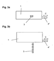
- the actuating element 4 can also, as shown in Figures 3a and 3b, as a sliding locking element 4 be formed, wherein an implementation of the rotational movement at the output B of the differential 5 in a linear movement, for example by a rack, can be done, including a toothing on the sliding Locking element 4 may be arranged.
- the displaceable locking element 4 acts with a arranged on the wing or on the frame locking device together and unlock the wing.
- the locking element 4 is required for unlocking Wheeloder Sliding motion blocked by a stop, causing the output B of the differential 5 is blocked.
- the torque applied to the differential can now cause a rotational movement on the output A, since the wing is unlocked and the actuator 3 from the drive 1 for pivoting the wing can be ejected.
- the drive element 2 In a corresponding pressed in opposite directions.
- the torque acts on both Drives A, B, since the actuator 3 and the locking element 4 actuated are.
- the brake 6 inhibits the Output B, whereby the torque of the drive element 2 is present at the output A. and the actuator 3 operates the wing in the closing direction. Reached the wing its closed position, the actuator 3, and thus the Output A, blocked.
- the torque now acts completely on the output B, wherein the braking force of the brake 6 overcome and the locking element 4th turned back or moved back and the locking device of the wing locking is actuated.
Landscapes
- Engineering & Computer Science (AREA)
- Mechanical Engineering (AREA)
- Power-Operated Mechanisms For Wings (AREA)
- Window Of Vehicle (AREA)
Abstract
Description
Der Abtrieb für die Verriegelung weist eine zumindest in Verriegelungsrichtung wirksame Bremse auf, durch welche beim Schließen des Flügels zuerst das Betätigungselement eingezogen wird. Durch die Betätigung des Antriebs zum Schließen des Flügels wird das in das Differential eingeleitete Drehmoment, durch diese Bremse bedingt, zunächst an dem Abtrieb für das Betätigungselement wirksam. Liegt der Flügel am Ende der Schließbewegung am Rahmen an, ist dieser Abtrieb blockiert und das gesamte Drehmoment wird an den Abtrieb für die Verriegelung abgegeben, wodurch die Bremse überwunden und die Verriegelung in die verriegelte Stellung geführt wird. Das Bremsmoment der Bremse kann einstellbar oder regelbar sein. Der Antrieb kann weiterhin eine Steuerung oder Regelung aufweisen, welche in Abhängigkeit von Flügel-Parametern, wie beispielsweise Flügelgewicht und Öffnungswinkel, die Momente der Abtriebe oder der Bremse bestimmt.
- Fig. 1
- eine Prinzipskizze eines Antriebs mit einem Differential zur Drehmomentverteilung;
- Fig. 2a
- ein Ausführungsbeispiel des Antriebs nach Fig. 1 mit Sicht auf das Betätigungselement;
- Fig. 2b
- den Antrieb nach Fig. 2a in der Draufsicht;
- Fig. 3a
- eine weitere Ausbildung des Antriebs nach Fig. 1 mit Sicht auf das Betätigungselement;
- Fig. 3b
- den Antrieb nach Fig. 3a in der Draufsicht.
- 1
- Antrieb
- 2
- Antriebselement
- 3
- Betätigungselement
- 4
- Verrieglungselement
- 5
- Differential
- 6
- Bremse
- A
- Abtrieb Betätigungselement
- B
- Abtrieb Verriegelungselement
- C
- Verschiebungsrichtung Verriegelungselement
Claims (5)
- Antrieb für einen Flügel eines Fensters oder einer Klappe, mit einem Antriebselement und mit einem in einer Führung des Antriebs verschiebbaren Betätigungselement zum Verschwenken des Flügels zwischen einer geschlossenen und einer geöffneten Stellung,
dadurch gekennzeichnet, dass der Antrieb (1) zur Steuerung der Flügelbewegung und einer Verrieglungseinrichtung des Flügels ein Differential (5) aufweist. - Antrieb nach Anspruch 1,
dadurch gekennzeichnet, dass das Differential (5) einen Abtrieb (A) und einen Abtrieb (B) aufweist, wobei der Abtrieb (A) mit dem Betätigungselement (3) zum Verschwenken des Flügels und der Abtrieb (B) mit einem Verriegelungselement (4) zur Betätigung der Verriegelungseinrichtung des Flügels, zusammenwirkt. - Antrieb nach Anspruch 2,
dadurch gekennzeichnet, dass der Abtrieb (B) mit einer Bremse (6) zusammenwirkt, welche den Abtrieb (B) zumindest in einer Bewegungsrichtung einstellbar oder regelbar hemmt. - Antrieb nach Anspruch 3,
dadurch gekennzeichnet, dass die Bremse (6) bei einer Betätigung des Antriebs (1) zum Öffnen des Flügels wirkungslos ist. - Antrieb nach Anspruch 2,
dadurch gekennzeichnet, dass das Verriegelungselement (4) an Stelle einer mechanischen Betätigungshandhabe mit der Verriegelungseinrichtung des Flügels zusammenwirkt.
Applications Claiming Priority (2)
| Application Number | Priority Date | Filing Date | Title |
|---|---|---|---|
| DE10329527 | 2003-06-30 | ||
| DE10329527A DE10329527A1 (de) | 2003-06-30 | 2003-06-30 | Antrieb für einen Flügel eines Fensters oder einer Klappe |
Publications (2)
| Publication Number | Publication Date |
|---|---|
| EP1493890A1 true EP1493890A1 (de) | 2005-01-05 |
| EP1493890B1 EP1493890B1 (de) | 2006-11-29 |
Family
ID=33426799
Family Applications (1)
| Application Number | Title | Priority Date | Filing Date |
|---|---|---|---|
| EP04006165A Expired - Lifetime EP1493890B1 (de) | 2003-06-30 | 2004-03-16 | Antrieb für einen Flügel eines Fensters oder einer Klappe |
Country Status (4)
| Country | Link |
|---|---|
| EP (1) | EP1493890B1 (de) |
| AT (1) | ATE347011T1 (de) |
| DE (2) | DE10329527A1 (de) |
| DK (1) | DK1493890T3 (de) |
Cited By (1)
| Publication number | Priority date | Publication date | Assignee | Title |
|---|---|---|---|---|
| WO2022069901A3 (en) * | 2020-10-01 | 2022-06-09 | Linear Building Innovations Limited | Smoke damper |
Citations (4)
| Publication number | Priority date | Publication date | Assignee | Title |
|---|---|---|---|---|
| US1815397A (en) * | 1927-02-05 | 1931-07-21 | Howard D Colman | Motor driven operator |
| US5050345A (en) * | 1988-12-28 | 1991-09-24 | Nakanishi Engineering Co., Ltd. | Window |
| EP0600105A1 (de) * | 1992-10-29 | 1994-06-08 | W. Hautau Gmbh | Kettenantrieb für ausstellbare Flügel von Fenstern, Türen oder dgl. |
| EP0644074A1 (de) * | 1993-09-13 | 1995-03-22 | Jan Dinkla | Mechanische Antriebseinrichtung für Schiebetür |
-
2003
- 2003-06-30 DE DE10329527A patent/DE10329527A1/de not_active Withdrawn
-
2004
- 2004-03-16 AT AT04006165T patent/ATE347011T1/de active
- 2004-03-16 EP EP04006165A patent/EP1493890B1/de not_active Expired - Lifetime
- 2004-03-16 DE DE502004002144T patent/DE502004002144D1/de not_active Expired - Lifetime
- 2004-03-16 DK DK04006165T patent/DK1493890T3/da active
Patent Citations (4)
| Publication number | Priority date | Publication date | Assignee | Title |
|---|---|---|---|---|
| US1815397A (en) * | 1927-02-05 | 1931-07-21 | Howard D Colman | Motor driven operator |
| US5050345A (en) * | 1988-12-28 | 1991-09-24 | Nakanishi Engineering Co., Ltd. | Window |
| EP0600105A1 (de) * | 1992-10-29 | 1994-06-08 | W. Hautau Gmbh | Kettenantrieb für ausstellbare Flügel von Fenstern, Türen oder dgl. |
| EP0644074A1 (de) * | 1993-09-13 | 1995-03-22 | Jan Dinkla | Mechanische Antriebseinrichtung für Schiebetür |
Cited By (2)
| Publication number | Priority date | Publication date | Assignee | Title |
|---|---|---|---|---|
| WO2022069901A3 (en) * | 2020-10-01 | 2022-06-09 | Linear Building Innovations Limited | Smoke damper |
| GB2602440A (en) * | 2020-10-01 | 2022-07-06 | Linear Building Innovations Ltd | Smoke damper |
Also Published As
| Publication number | Publication date |
|---|---|
| ATE347011T1 (de) | 2006-12-15 |
| DE502004002144D1 (de) | 2007-01-11 |
| DK1493890T3 (da) | 2007-04-02 |
| DE10329527A1 (de) | 2005-02-03 |
| EP1493890B1 (de) | 2006-11-29 |
Similar Documents
| Publication | Publication Date | Title |
|---|---|---|
| EP3942138B1 (de) | Aufstellvorrichtung für ein kraftfahrzeugtürelement | |
| EP3899179B1 (de) | Aufstellvorrichtung für ein kraftfahrzeugtürelement | |
| WO2012095084A1 (de) | Betätigungsvorrichtunq für eine fahrzeugtür | |
| EP1603213B1 (de) | Motorische Kraftfahrzeugkomponente | |
| DE102020101806A1 (de) | Aufstellvorrichtung für eine Kraftfahrzeugtür | |
| EP2166181B1 (de) | Steuerantrieb für ein Kraftfahrzeugschloss | |
| EP1947274B1 (de) | Antriebseinrichtung für einen Treibstangenbeschlag | |
| DD219985A5 (de) | Ausschwingtuer mit betaetigungseinrichtung | |
| DE2854713C2 (de) | ||
| EP3401475A1 (de) | Beschlaganordnung | |
| EP1507059B1 (de) | Hebeschiebebeschlag | |
| EP0600228B1 (de) | Vorrichtung zum Öffnen und Schliessen eines Lukendeckels an einem Kampffahrzeug, insbesondere einem Kampfpanzer | |
| EP1865130B1 (de) | Entriegelungsanordnung eines Fensters, einer Tür oder dergleichen | |
| DE10237492B3 (de) | Vorrichtung zum Öffnen und/oder Schließen eines Flügels relativ zu einem Rahmenstock | |
| DE102009050875A1 (de) | Vorrichtung zum Öffnen und Schließen von Fenstern an Wohnwagen, Wohnmobilen und dergleichen | |
| DE19713863C1 (de) | Kraftfahrzeugtürschloß, insbesondere Heckklappenschloß oder Seitentürschloß | |
| EP1243728B1 (de) | Antriebseinheit für Fenster oder Türen | |
| DE102020132139A1 (de) | Zuzieheinrichtung für ein Kraftfahrzeug-Schloss | |
| DE60121495T2 (de) | Verriegelungsvorrichtung | |
| DE19616299B4 (de) | Schließ- bzw. Öffnungshilfe für ein Verschließteil | |
| EP1493890B1 (de) | Antrieb für einen Flügel eines Fensters oder einer Klappe | |
| EP1529908A2 (de) | Verschluss für Verdecke, Klappen oder dergleichen an Fahrzeugen | |
| EP1288418B1 (de) | Beschlagseinheit für ein Kipp- oder Drehkippfenster | |
| EP2835487A1 (de) | Klappeneinrichtung eines Gebäudes | |
| EP1493892B1 (de) | Verriegelung für den Flügel eines Fensters oder einer Klappe |
Legal Events
| Date | Code | Title | Description |
|---|---|---|---|
| PUAI | Public reference made under article 153(3) epc to a published international application that has entered the european phase |
Free format text: ORIGINAL CODE: 0009012 |
|
| AK | Designated contracting states |
Kind code of ref document: A1 Designated state(s): AT BE BG CH CY CZ DE DK EE ES FI FR GB GR HU IE IT LI LU MC NL PL PT RO SE SI SK TR |
|
| AX | Request for extension of the european patent |
Extension state: AL LT LV MK |
|
| 17P | Request for examination filed |
Effective date: 20050701 |
|
| AKX | Designation fees paid |
Designated state(s): AT BE BG CH CY CZ DE DK EE ES FI FR GB GR HU IE IT LI LU MC NL PL PT RO SE SI SK TR |
|
| GRAP | Despatch of communication of intention to grant a patent |
Free format text: ORIGINAL CODE: EPIDOSNIGR1 |
|
| GRAS | Grant fee paid |
Free format text: ORIGINAL CODE: EPIDOSNIGR3 |
|
| GRAA | (expected) grant |
Free format text: ORIGINAL CODE: 0009210 |
|
| AK | Designated contracting states |
Kind code of ref document: B1 Designated state(s): AT BE BG CH CY CZ DE DK EE ES FI FR GB GR HU IE IT LI LU MC NL PL PT RO SE SI SK TR |
|
| PG25 | Lapsed in a contracting state [announced via postgrant information from national office to epo] |
Ref country code: IT Free format text: LAPSE BECAUSE OF FAILURE TO SUBMIT A TRANSLATION OF THE DESCRIPTION OR TO PAY THE FEE WITHIN THE PRESCRIBED TIME-LIMIT;WARNING: LAPSES OF ITALIAN PATENTS WITH EFFECTIVE DATE BEFORE 2007 MAY HAVE OCCURRED AT ANY TIME BEFORE 2007. THE CORRECT EFFECTIVE DATE MAY BE DIFFERENT FROM THE ONE RECORDED. Effective date: 20061129 Ref country code: RO Free format text: LAPSE BECAUSE OF FAILURE TO SUBMIT A TRANSLATION OF THE DESCRIPTION OR TO PAY THE FEE WITHIN THE PRESCRIBED TIME-LIMIT Effective date: 20061129 Ref country code: SK Free format text: LAPSE BECAUSE OF FAILURE TO SUBMIT A TRANSLATION OF THE DESCRIPTION OR TO PAY THE FEE WITHIN THE PRESCRIBED TIME-LIMIT Effective date: 20061129 Ref country code: IE Free format text: LAPSE BECAUSE OF FAILURE TO SUBMIT A TRANSLATION OF THE DESCRIPTION OR TO PAY THE FEE WITHIN THE PRESCRIBED TIME-LIMIT Effective date: 20061129 Ref country code: SI Free format text: LAPSE BECAUSE OF FAILURE TO SUBMIT A TRANSLATION OF THE DESCRIPTION OR TO PAY THE FEE WITHIN THE PRESCRIBED TIME-LIMIT Effective date: 20061129 Ref country code: CZ Free format text: LAPSE BECAUSE OF FAILURE TO SUBMIT A TRANSLATION OF THE DESCRIPTION OR TO PAY THE FEE WITHIN THE PRESCRIBED TIME-LIMIT Effective date: 20061129 Ref country code: FI Free format text: LAPSE BECAUSE OF FAILURE TO SUBMIT A TRANSLATION OF THE DESCRIPTION OR TO PAY THE FEE WITHIN THE PRESCRIBED TIME-LIMIT Effective date: 20061129 Ref country code: PL Free format text: LAPSE BECAUSE OF FAILURE TO SUBMIT A TRANSLATION OF THE DESCRIPTION OR TO PAY THE FEE WITHIN THE PRESCRIBED TIME-LIMIT Effective date: 20061129 |
|
| REG | Reference to a national code |
Ref country code: GB Ref legal event code: FG4D Free format text: NOT ENGLISH |
|
| REG | Reference to a national code |
Ref country code: CH Ref legal event code: NV Representative=s name: E. BLUM & CO. PATENTANWAELTE Ref country code: CH Ref legal event code: EP |
|
| REG | Reference to a national code |
Ref country code: IE Ref legal event code: FG4D Free format text: LANGUAGE OF EP DOCUMENT: GERMAN |
|
| REF | Corresponds to: |
Ref document number: 502004002144 Country of ref document: DE Date of ref document: 20070111 Kind code of ref document: P |
|
| GBT | Gb: translation of ep patent filed (gb section 77(6)(a)/1977) |
Effective date: 20070110 |
|
| PG25 | Lapsed in a contracting state [announced via postgrant information from national office to epo] |
Ref country code: BG Free format text: LAPSE BECAUSE OF FAILURE TO SUBMIT A TRANSLATION OF THE DESCRIPTION OR TO PAY THE FEE WITHIN THE PRESCRIBED TIME-LIMIT Effective date: 20070228 |
|
| PG25 | Lapsed in a contracting state [announced via postgrant information from national office to epo] |
Ref country code: ES Free format text: LAPSE BECAUSE OF FAILURE TO SUBMIT A TRANSLATION OF THE DESCRIPTION OR TO PAY THE FEE WITHIN THE PRESCRIBED TIME-LIMIT Effective date: 20070312 |
|
| REG | Reference to a national code |
Ref country code: SE Ref legal event code: TRGR |
|
| REG | Reference to a national code |
Ref country code: DK Ref legal event code: T3 |
|
| PG25 | Lapsed in a contracting state [announced via postgrant information from national office to epo] |
Ref country code: PT Free format text: LAPSE BECAUSE OF FAILURE TO SUBMIT A TRANSLATION OF THE DESCRIPTION OR TO PAY THE FEE WITHIN THE PRESCRIBED TIME-LIMIT Effective date: 20070430 |
|
| ET | Fr: translation filed | ||
| REG | Reference to a national code |
Ref country code: IE Ref legal event code: FD4D |
|
| PLBE | No opposition filed within time limit |
Free format text: ORIGINAL CODE: 0009261 |
|
| STAA | Information on the status of an ep patent application or granted ep patent |
Free format text: STATUS: NO OPPOSITION FILED WITHIN TIME LIMIT |
|
| REG | Reference to a national code |
Ref country code: CH Ref legal event code: PFA Owner name: GEZE GMBH Free format text: GEZE GMBH#REINHOLD-VOESTER-STRASSE 21-29#71229 LEONBERG (DE) -TRANSFER TO- GEZE GMBH#REINHOLD-VOESTER-STRASSE 21-29#71229 LEONBERG (DE) |
|
| 26N | No opposition filed |
Effective date: 20070830 |
|
| BERE | Be: lapsed |
Owner name: GEZE G.M.B.H. Effective date: 20070331 |
|
| PG25 | Lapsed in a contracting state [announced via postgrant information from national office to epo] |
Ref country code: BE Free format text: LAPSE BECAUSE OF NON-PAYMENT OF DUE FEES Effective date: 20070331 |
|
| PG25 | Lapsed in a contracting state [announced via postgrant information from national office to epo] |
Ref country code: MC Free format text: LAPSE BECAUSE OF NON-PAYMENT OF DUE FEES Effective date: 20070331 |
|
| PG25 | Lapsed in a contracting state [announced via postgrant information from national office to epo] |
Ref country code: GR Free format text: LAPSE BECAUSE OF FAILURE TO SUBMIT A TRANSLATION OF THE DESCRIPTION OR TO PAY THE FEE WITHIN THE PRESCRIBED TIME-LIMIT Effective date: 20070301 |
|
| PG25 | Lapsed in a contracting state [announced via postgrant information from national office to epo] |
Ref country code: EE Free format text: LAPSE BECAUSE OF FAILURE TO SUBMIT A TRANSLATION OF THE DESCRIPTION OR TO PAY THE FEE WITHIN THE PRESCRIBED TIME-LIMIT Effective date: 20061129 |
|
| PG25 | Lapsed in a contracting state [announced via postgrant information from national office to epo] |
Ref country code: LU Free format text: LAPSE BECAUSE OF NON-PAYMENT OF DUE FEES Effective date: 20070316 Ref country code: CY Free format text: LAPSE BECAUSE OF FAILURE TO SUBMIT A TRANSLATION OF THE DESCRIPTION OR TO PAY THE FEE WITHIN THE PRESCRIBED TIME-LIMIT Effective date: 20061129 |
|
| PG25 | Lapsed in a contracting state [announced via postgrant information from national office to epo] |
Ref country code: HU Free format text: LAPSE BECAUSE OF FAILURE TO SUBMIT A TRANSLATION OF THE DESCRIPTION OR TO PAY THE FEE WITHIN THE PRESCRIBED TIME-LIMIT Effective date: 20070530 Ref country code: TR Free format text: LAPSE BECAUSE OF FAILURE TO SUBMIT A TRANSLATION OF THE DESCRIPTION OR TO PAY THE FEE WITHIN THE PRESCRIBED TIME-LIMIT Effective date: 20061129 |
|
| REG | Reference to a national code |
Ref country code: FR Ref legal event code: PLFP Year of fee payment: 13 |
|
| REG | Reference to a national code |
Ref country code: FR Ref legal event code: PLFP Year of fee payment: 14 |
|
| REG | Reference to a national code |
Ref country code: FR Ref legal event code: PLFP Year of fee payment: 15 |
|
| PGFP | Annual fee paid to national office [announced via postgrant information from national office to epo] |
Ref country code: DK Payment date: 20180321 Year of fee payment: 15 Ref country code: GB Payment date: 20180321 Year of fee payment: 15 Ref country code: NL Payment date: 20180321 Year of fee payment: 15 Ref country code: CH Payment date: 20180321 Year of fee payment: 15 |
|
| PGFP | Annual fee paid to national office [announced via postgrant information from national office to epo] |
Ref country code: SE Payment date: 20180321 Year of fee payment: 15 Ref country code: FR Payment date: 20180323 Year of fee payment: 15 Ref country code: AT Payment date: 20180322 Year of fee payment: 15 |
|
| PGFP | Annual fee paid to national office [announced via postgrant information from national office to epo] |
Ref country code: DE Payment date: 20180331 Year of fee payment: 15 |
|
| PGFP | Annual fee paid to national office [announced via postgrant information from national office to epo] |
Ref country code: IT Payment date: 20180327 Year of fee payment: 15 |
|
| REG | Reference to a national code |
Ref country code: DE Ref legal event code: R231 Ref document number: 502004002144 Country of ref document: DE |
|
| PG25 | Lapsed in a contracting state [announced via postgrant information from national office to epo] |
Ref country code: DE Free format text: LAPSE BECAUSE OF THE APPLICANT RENOUNCES Effective date: 20190215 |
|
| REG | Reference to a national code |
Ref country code: DK Ref legal event code: EBP Effective date: 20190331 |
|
| REG | Reference to a national code |
Ref country code: SE Ref legal event code: EUG |
|
| PG25 | Lapsed in a contracting state [announced via postgrant information from national office to epo] |
Ref country code: SE Free format text: LAPSE BECAUSE OF NON-PAYMENT OF DUE FEES Effective date: 20190317 |
|
| REG | Reference to a national code |
Ref country code: CH Ref legal event code: PL |
|
| REG | Reference to a national code |
Ref country code: NL Ref legal event code: MM Effective date: 20190401 |
|
| REG | Reference to a national code |
Ref country code: AT Ref legal event code: MM01 Ref document number: 347011 Country of ref document: AT Kind code of ref document: T Effective date: 20190316 |
|
| GBPC | Gb: european patent ceased through non-payment of renewal fee |
Effective date: 20190316 |
|
| PG25 | Lapsed in a contracting state [announced via postgrant information from national office to epo] |
Ref country code: GB Free format text: LAPSE BECAUSE OF NON-PAYMENT OF DUE FEES Effective date: 20190316 Ref country code: CH Free format text: LAPSE BECAUSE OF NON-PAYMENT OF DUE FEES Effective date: 20190331 Ref country code: LI Free format text: LAPSE BECAUSE OF NON-PAYMENT OF DUE FEES Effective date: 20190331 Ref country code: AT Free format text: LAPSE BECAUSE OF NON-PAYMENT OF DUE FEES Effective date: 20190316 Ref country code: NL Free format text: LAPSE BECAUSE OF NON-PAYMENT OF DUE FEES Effective date: 20190401 |
|
| PG25 | Lapsed in a contracting state [announced via postgrant information from national office to epo] |
Ref country code: FR Free format text: LAPSE BECAUSE OF NON-PAYMENT OF DUE FEES Effective date: 20190331 Ref country code: IT Free format text: LAPSE BECAUSE OF NON-PAYMENT OF DUE FEES Effective date: 20190316 |
|
| PG25 | Lapsed in a contracting state [announced via postgrant information from national office to epo] |
Ref country code: DK Free format text: LAPSE BECAUSE OF NON-PAYMENT OF DUE FEES Effective date: 20190331 |
|
| P01 | Opt-out of the competence of the unified patent court (upc) registered |
Free format text: CASE NUMBER: UPC_APP_119260/2023 Effective date: 20230510 |