EP1486752B1 - Panzerelement - Google Patents
Panzerelement Download PDFInfo
- Publication number
- EP1486752B1 EP1486752B1 EP04011751A EP04011751A EP1486752B1 EP 1486752 B1 EP1486752 B1 EP 1486752B1 EP 04011751 A EP04011751 A EP 04011751A EP 04011751 A EP04011751 A EP 04011751A EP 1486752 B1 EP1486752 B1 EP 1486752B1
- Authority
- EP
- European Patent Office
- Prior art keywords
- elements
- pockets
- layer
- armouring
- Prior art date
- Legal status (The legal status is an assumption and is not a legal conclusion. Google has not performed a legal analysis and makes no representation as to the accuracy of the status listed.)
- Expired - Lifetime
Links
- 239000004744 fabric Substances 0.000 claims description 16
- 230000001681 protective effect Effects 0.000 claims description 15
- 230000016571 aggressive behavior Effects 0.000 description 4
- 239000000463 material Substances 0.000 description 4
- 238000012423 maintenance Methods 0.000 description 3
- 238000011084 recovery Methods 0.000 description 3
- 238000003780 insertion Methods 0.000 description 2
- 230000037431 insertion Effects 0.000 description 2
- 238000009434 installation Methods 0.000 description 2
- 230000006978 adaptation Effects 0.000 description 1
- 230000000295 complement effect Effects 0.000 description 1
- 239000000470 constituent Substances 0.000 description 1
- 238000013016 damping Methods 0.000 description 1
- 230000009977 dual effect Effects 0.000 description 1
- 230000000694 effects Effects 0.000 description 1
- 239000000835 fiber Substances 0.000 description 1
- 235000019589 hardness Nutrition 0.000 description 1
- 239000011347 resin Substances 0.000 description 1
- 229920005989 resin Polymers 0.000 description 1
- 238000009958 sewing Methods 0.000 description 1
- 238000007493 shaping process Methods 0.000 description 1
- 230000035939 shock Effects 0.000 description 1
- 239000012780 transparent material Substances 0.000 description 1
Images



Classifications
-
- F—MECHANICAL ENGINEERING; LIGHTING; HEATING; WEAPONS; BLASTING
- F41—WEAPONS
- F41H—ARMOUR; ARMOURED TURRETS; ARMOURED OR ARMED VEHICLES; MEANS OF ATTACK OR DEFENCE, e.g. CAMOUFLAGE, IN GENERAL
- F41H5/00—Armour; Armour plates
- F41H5/02—Plate construction
- F41H5/04—Plate construction composed of more than one layer
- F41H5/0492—Layered armour containing hard elements, e.g. plates, spheres, rods, separated from each other, the elements being connected to a further flexible layer or being embedded in a plastics or an elastomer matrix
Definitions
- the present invention relates to a shielded protection device for protecting persons, equipment or other projectiles or splinters generated directly or indirectly by the projectiles.
- the persons and / or equipment to be protected can be found in vehicles of the air, land or sea type, as well as in buildings, shelters or any other place.
- US Pat. No. 5,448,938 describes a shielding plate protection device, adapted strictly to seats, in particular for helicopters, and of which each plate is appropriate for the dimensions of the components of the seat.
- This device comprises several juxtaposed chambers, interconnected and each containing a shielding plate, and its holding at the seat is provided by specific fastening means provided on both the seat and the device.
- this known device may have breaks in protection between adjacent rooms so that it does not offer all the necessary guarantees.
- US Pat. No. 5,771,489 also discloses an armored body plate consisting of armor plates interconnected by cylindrical joints which are situated at the level of the edges of the plates. In some places, the edges of two plates are thinned and overlap one another with a relative slip to cover the plates in case of misalignment due to stresses on the plastron. On this plate overlap zone, resilient elements are provided allowing the plates to be returned to position when the stresses are relaxed.
- Such a protective plastron does not offer, either, all the desired requirements. Indeed, the presented cylindrical articulation connecting two plates does not allow to obtain a large angular movement between two successive plates, so that the front plate can not adapt to any contours. In addition, even if there is recovery between certain plates, there is relative sliding between said plates, so that after a certain gap, the continuity of the protection is no longer ensured.
- U.S. Patent No. 5,395,671 discloses a fabric composed of high molecular weight polymeric fibers and provides multi-layer, projectile resistant garments.
- Another US Pat. No. 6,127,291 teaches an anti-ballistic fabric composed of layers of fabric and rubbery resin. If these fabrics are effective vis-à-vis the protection against the projectiles of handguns, however, they are not suitable when it comes to more powerful weapons and do not have sufficient resistance to perforations. And a stack of several layers of these fabrics to meet the protection objectives would lose all flexibility of use to these tissues.
- Another protective device is also known composed of a plurality of plates hinged together and able to occupy a first folded position for its transport and a second deployed position for the protection of a person.
- the break in protection between the articulated plates in the deployed position does not offer real efficiency.
- the present invention aims to overcome the disadvantages of the proposed solutions described above and it relates to a protection device whose design allows to meet the previously stated criteria for maximum protection.
- connection means between two consecutive alternating and overlapping pockets of the first and second layers are of the type self-gripping strips.
- a continuous and total protection is not only obtained when the device is taken a substantially rectilinear configuration, but also when it is made take a curved and / or broken configuration thanks to the receiving pockets of the elements preventing the sliding of the latter and the connecting means articulated between the pockets which maintain the overlap of the elements and prevent their removal from each other.
- This device can be compared to an overlapping hinged coverage of the constituent elements, thus tracking any surface to be protected without discontinuity.
- said shielding elements have a substantially parallelepipedal shape with two parallel and opposite edges, said edges of a shielding element of one of the layers overlapping with the corresponding edges of the two adjacent shielding elements of the other layer.
- said pockets containing said Shielding elements are made of fabric.
- Each pocket can be made loosely with respect to the element it contains or the fabric of each of them can be at least partially elastic, to allow, on the one hand, free angular movement between the pockets and follow thus at best the profile of the surface to be protected by maintaining a overlapped contact of the shielding elements and, on the other hand, the insertion and removal of the elements of the pockets.
- Each pocket also has a quick-closing device.
- each pocket of one of the layers is then provided with two opposite self-gripping strips extending the parallel edges of the pocket around hinge lines, and each pocket of the other layer has on a large face of the pocket, two articulated self-gripping parallel strips, with which the corresponding self-gripping strips of two adjacent pockets of the opposite layer cooperate.
- said connecting means between two consecutive alternating and overlapping pockets of the first and second layers may comprise an elastic band whose longitudinal edges are fixed on a large face of the pocket of a layer and its middle part is fixed to the lateral edge in correspondence of the pocket of the other layer.
- auxiliary elements may be provided in the spaces left between said shielding elements of each layer. They preferably have a parallelepiped shape with a thickness substantially identical to that of the shielding elements, which ensures the continuity of the device.
- auxiliary elements may be flexible elements and / or shielding elements as well.
- the device could comprise flexible or shielded auxiliary elements on the two layers or on one of the layers only, according to the desired requirements.
- the auxiliary elements are housed in receiving pockets. These pockets containing said auxiliary elements are then fixedly attached, removably, to the corresponding pockets containing said shielding elements.
- said pockets containing the elements of the two layers are housed in a receiving cover, ensuring complete cohesion to all the elements and facilitating in particular its transport and its implementation.
- said pockets are held in position in said cover by means of self-gripping strips.
- said cover comprises two superimposed compartments, one of which contains the two layers of elements (facing the aggression zone) and the other of which encloses a protective mattress (turned towards the zone to be protected (persons, materials )).
- said cover has flaps for closing said compartments and is provided with gripping means for its transport.
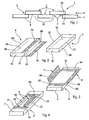
- the figure 1 schematically shows a protective device with shielding elements whose arrangement is in accordance with the present invention.
- the figure 2 is a schematic perspective view showing a shielding element and its receiving pocket.
- FIGS 3 and 4 show, in schematic perspective, an embodiment of the connecting means between the pockets, by self-gripping strips.
- the figure 5 represents, in cross-section, a preferred protection device, in rectilinear configuration of the shielding elements.
- the Figures 6 and 7 represent the device of the figure 5 respectively with a convex curvature and a concave curvature of said shielding element pockets.
- the figure 8 shows, in cross-section, a preferred embodiment with two compartments of the protection device according to the invention, with shielding elements and auxiliary elements.
- the figure 9 is a partial perspective of this device the figure 8 .
- the figure 10 is a cross section of the different layers of the second compartment.
- the figure 11 schematically represents another embodiment of said connecting means.
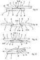
- FIGS 12 and 13 represent another embodiment of the shielding elements, with two distinct configurations.
- the figure 14 shows in perspective a preferred shielding element with connection means common to all the pockets.
- the figure 15 schematically represents a particular application of said protection device according to the invention.
- the protective device 1 diagrammatically and partially shown on the figure 1 consists of a plurality of shielding elements 2 associated with each other by connecting means 3 and intended to provide adequate protection of persons and / or equipment against projectiles and splinters.
- the nature of the materials constituting such shielding elements can be of any known type and will not be described here.
- the shielding elements 2 are arranged in two layers 4 and 5 superimposed alternately with respect to each other and so that two consecutive alternating elements of the first layer 4 and the second layer 5 overlap.
- the protection conferred by the device 1 is continuous and extends over its entire surface since there is recovery of the shielding elements 2 in the manner of roof tiles overlapping.
- the shielding elements 2 also referred to as modules thereafter, may have any shapes and thicknesses depending on the surfaces to be protected, and in this example have a parallelepipedal shape such as that shown in FIG. figure 2 , that is to say with two large opposite side faces 2A, two small opposite side faces 2B and two opposite transverse faces 2C.
- the two lateral parallel edges 2D of the modules of the first layer 4 cover the parallel lateral edges 2D of the modules of the second layer 5.
- each pocket 6 has a configuration substantially similar to that of the modules 2 although dimensionally larger for the insertion and removal of the module.
- Each pocket 6 has two large lateral faces 6A, two small lateral faces 6B, one of which constitutes an articulated flap 6C around a longitudinal fold line 6D and intended to enclose the module 2 in the pocket, and two transverse faces 6E.
- a closure device of the pocket is provided and is defined, in this embodiment, by a self-gripping strip 7A fixed to the flap 6C and cooperating with a corresponding self-gripping strip 7B, provided on the open longitudinal edge 6F of the big face 6A of the pocket. Any other means of closure could also be considered.
- a fabric is preferred as soon as it offers good resistance to use and, in particular, good tensile strength to withstand the forces induced by the deformations during installation. of the device 1.
- connecting means 3 A particular embodiment of the connecting means 3 will be explained below with regard to Figures 3 and 4 .
- the connecting means 3 are of the self-gripping band type 8, 9 because of the simplicity of implementation of such a connection.
- the pockets 6 containing for example the modules of the first layer 4 have two opposite and identical side bands 8, fixedly attached, by sewing or otherwise, on the edges or parallel angles 6G of a main face 6A with its small side faces 6B, which edges define the lines of articulation 8A bands. These can also be reported on flaps provided on the pocket.
- Such pocket 6 may be designated male pocket.
- the pockets 6 containing the modules of the second layer 5 they also comprise two self-gripping strips 9 which are attached, not at the level of the lateral edges, but directly on the large face 6A of the pocket, parallel to the side edges 6G.
- Each band 9 is folded in the direction of its length, so that a half-band 9A is fixed to the face of the pocket and the other half-band 9B extends the previous around the fold line 9C of the bandaged.
- Such pocket 6 is then designated female pocket.
- connection between two consecutive alternating pockets (male-female) of the first and second layers 4, 5 is simply carried out without difficulty, by inserting one of the self-gripping lateral strips 8 of the male pocket between the two Velcro strips 9A, 9B of the female pocket, then folding the free half-band 9B against the half-band 9A fixed on the large face 6A of the pocket, which has the effect of wrapping said strip 8 and securely hang the strips together.
- the arrangement of the folded strips 9 on the pockets 6 of a layer is such that, when the strips 8 of the pockets of the other layer are inserted into the folded strips, the 2D lateral edges of the modules contained in the pockets are overlap.
- Such a connection between three consecutive alternating pockets (two male pockets of the first layer 4 and a female pocket of the second layer 5) of a protective device 1 is illustrated schematically on the figure 5 . The thickness of the strips has been exaggerated for the sake of clarity.
- the portion of device 1 represented on the figure 5 applies in particular to the protection of equipment or other symbolically illustrated by a flat surface S and located in the area to be protected ZP (opposite to the zone of aggression ZA from which the projectiles originate), so that the pockets 6 modules 2 are substantially rectilinear and overlap two by two.
- the portion of the device 1 can effectively protect a convex surface S through the overlap of the modules and the flexible links 3 advantageously provided on the receiving pockets 6.
- the end modules 2 of the first layer can pivot around the edges 6G of said female pocket of the second layer.
- the represented portion of the device 1 protects a concave surface S.
- the pivoting of the modules of the male pockets is effected at the level of the hinge lines 8A of the female pockets containing the modules, which "rise” by turning around it said lines.
- the receiving pockets 6 have a certain extent compared to the shielding modules 2, as is exaggeratedly shown in FIG. figure 6 , the fabric deforms somewhat but maintains an overlap between the different shielding modules.
- the device 1 may comprise auxiliary elements 11 ensuring the continuity of the device and having, for this, a parallelepiped shape with substantially the same thickness as that of the initial elements 2.
- auxiliary elements 11 may be flexible elements, not remanent , absorbing impacts and protecting against rear deformations of shielding elements, or even shielding elements or other. Again, they are each housed in a receiving pocket 12 identical in design to the previous (fabric and closure device).
- the device obtained 1 with the shielding modules 2 and the auxiliary modules 11 is shown on the figure 8 , a gap being left between the auxiliary modules and the shielding modules to maintain their angular freedom around the connecting means 3, and thus allow the device 1 to best follow the surfaces to be protected.
- auxiliary modules 11 of one of the layers on the opposite armor modules 2 of the other layer and vice versa is effected, again, by self-gripping strips provided transversely on the large internal surface 6A pockets 6 and on the large inner corresponding face 12A of the pockets 12, as the two transverse strips 14 shown on the figure 3 . Thanks to the removable nature of this type of connection, the auxiliary modules 11 can be easily removed or replaced, if necessary, while being properly fixed.
- the protective device 1 may also include a cover 15 enveloping the two layers of modules 4 and 5 to ensure complete cohesion to this set of elements or modules.
- the cover 15 contains, in a first compartment 16, all of the two layers 4, 5 of modules 2, 11 which are arranged transversely with respect to its length, that is to say in the direction of its width, and in a second compartment 17 superimposed on the first, a protective mat 18 of the anti-traumatic type.
- This protective device 1 is of course arranged so as to have its first compartment 16 facing the zone of aggression ZA and its second compartment 17 facing the area to be protected ZP (person, equipment, ...), as shown the figure 8 .
- each compartment 16 and 17 is closed by cooperating flaps 15B whose closure is obtained by means of fastening system of the self-gripping tape type, not shown, facilitating the maintenance and repair operations. subsequent maintenance.
- a shock absorbing belt 20 known per se can be provided in the first compartment 16, being located between the cover and the modules of the first layer.
- This mat 20 can be attached to the flaps of the second compartment.
- the anti-traumatic mattress 18 ensures both the protection against the rear deformations of the armor modules 2 as a result of the impacts of bullets or others from the aggression zone ZA, and the comfort of sitting or support as will be seen on the figure 15 .
- This dual function is thus optimized by combining damping layers 18A, known per se, and having different and complementary thicknesses, densities and hardnesses as shown in FIG. figure 10 .
- holding handles of the device may be attached to the cover with a passage therethrough.
- Straps equipped with a system of setting to length for the attachment and the maintenance of the whole of the device can be also fixed with a passage through the cover, which makes it possible to fix and to adapt as well as possible the device to any means of attachment not initially provided for this purpose.
- the elastic band 21 is arranged parallel to the side edges of the pockets 6 (and therefore modules) and is fixed, by seams or the like 22, at its longitudinal ends 21A, to the face 6A of a pocket, so close to its edge, and in the middle 21 B, the corresponding edge 6G of the other pocket 6 whose edge overlaps that of the previous pocket.
- FIG. 12 An alternative embodiment of the shielding elements or modules 2 is also represented on the figure 12 .
- two identical and parallel chamfers 2E are formed at the longitudinal corners of the same large face 2A of a module.
- This arrangement facilitates the angular movement between the consecutive pockets 6 enveloping the modules and which overlap alternately around the connecting means 3 symbolized by a black circle in the figure.
- the presence of these chamfers 2E makes it possible to avoid tension in the fabric of the pockets 6, especially when the device 1 protects a convex surface as on the figure 7 since the modules of the first layer can pivot freely around the hinge lines 8A by the creation of the chamfers.
- the modules are arranged in the same direction with the chamfers facing upward, it is necessary to have two types of pockets (female males) with the connecting means 3.
- figure 13 presents a configuration where the modules 2 contained in the pockets 6 are arranged head to tail and the hinge line of the connecting means 3 (symbolized by a black circle) is located on the edges 2F between the chamfer 2E and the corresponding face 2A of the modules in vis-a-vis.
- the advantage of this configuration is that a single pocket model 6 is necessary and whatever the type of connection means 3 between the pockets of the shielding modules. Indeed, even in the case of Velcro strips 8, 9, the arrangement of these on the pockets becomes unique, as shown in FIG. figure 14 .
- One of the edges 2F defining the line 8A carries the self-gripping tape 8, while the other edge 2F carries the folded strip 9.
- This last embodiment is particularly advantageous insofar as it makes it possible to standardize the receiving pockets, the modules and the connecting means and to simplify the assembly.
- the protection device 1 covers, in the manner of a hinged cover, a seat or a seat 25, for example a helicopter, so as to isolate the occupants (zone ZP) of the projectiles at best from the ground (zone ZA).
- the cover envelops all of the two layers, with the first compartment containing the pockets 6 to 2 modules in contact with the seat 25 and the second compartment with anti-traumatic mattress supporting the occupant.
- the overlap of the modules 2 continuously protects the occupant (s) while being able to adapt to the shapes of the seat thanks to the connection means 3 allowing their pivoting.
- the holding in position of the protective device 1 on the seat 25 can be provided with or without the addition of retaining straps.
- the ballistic protection is continuously ensured by the recovery of the modules to the right of the links.
- the size and number of modules depend on the threats and applications to consider.
- the installation of the protection device is carried out without prior adaptation of the place of use by a system of straps with quick adjustment and fixing.
- the modules are also easily interchangeable or replaceable thanks to the quick disassembly of the articulation links and the quick opening of the pockets.
- the device can be placed on floors, floors, benches, walls or any other surface and even suspended and take concave and / or convex configurations at several points of inflection.
Landscapes
- Engineering & Computer Science (AREA)
- General Engineering & Computer Science (AREA)
- Insulated Conductors (AREA)
- Aiming, Guidance, Guns With A Light Source, Armor, Camouflage, And Targets (AREA)
- Laying Of Electric Cables Or Lines Outside (AREA)
- Finger-Pressure Massage (AREA)
- Headphones And Earphones (AREA)
- Temperature-Responsive Valves (AREA)
- Paper (AREA)
- Emergency Protection Circuit Devices (AREA)
- Control Of Motors That Do Not Use Commutators (AREA)
- Mattresses And Other Support Structures For Chairs And Beds (AREA)
- Tents Or Canopies (AREA)
Claims (18)
- Gepanzerte Schutzvorrichtung für Personen, Ausrüstungen oder anderes, von dem Typ, die mehrere Panzerungselemente (2) aufweist, die durch Verbindungsmittel (3) miteinander verbunden sind, wobei:- die Panzerungselemente (2) in zwei getrennten, übereinander angeordneten Schichten (4, 5) einander abwechselnd und so angeordnet werden, dass zwei abwechselnde aufeinander folgende Elemente der ersten Schicht (4) und der zweiten Schicht (5) sich überlappen;- jedes Panzerungselement (2) in einer Aufnahmetasche (6) angeordnet ist; und- die Verbindungsmittel (3) zwei aufeinander folgende, die zwei aufeinander folgenden abwechselnden Elemente (2) der ersten Schicht (4) bzw. der zweiten Schicht (5), die sich überlappen, enthaltende Taschen (6) um Gelenklinien herum vereinen, um die die Taschen (6) zueinander schwenken können und dabei miteinander in Kontakt bleiben, wobei diese zwischen den Taschen gelenkig verbundenen Verbindungsmittel das Überlappen der Elemente (2) aufrechterhalten und ihr Entfernen voneinander verhindern,wobei die Panzerungselemente (2) eine im Wesentlichen parallelepipedische Form mit zwei parallelen und gegenüberliegenden Rändern (2D) haben, wobei die Ränder eines Panzerungselements einer der Schichten die entsprechenden Ränder (2D) der zwei benachbarten Panzerungselemente der anderen Schicht überlappen,
dadurch gekennzeichnet, dass die Verbindungsmittel (3) zwischen zwei abwechselnden aufeinander folgenden und überlappenden Taschen der ersten und der zweiten Schicht selbsthaftende Streifen (8, 9) aufweisen. - Vorrichtung nach Anspruch 1, dadurch gekennzeichnet, dass die parallelen und gegenüberliegenden Ränder (2D) mit einer Abschrägung (2E) versehen sind.
- Vorrichtung nach einem der Ansprüche 1 oder 2, dadurch gekennzeichnet, dass die die Panzerungselemente (2) enthaltenden Taschen (6) aus Stoff hergestellt sind.
- Vorrichtung nach Anspruch 3, dadurch gekennzeichnet, dass jede Tasche (6) bezüglich des Panzerungselements, das sie enthält, geräumig hergestellt ist.
- Vorrichtung nach Anspruch 3, dadurch gekennzeichnet, dass der Stoff jeder der Taschen (6) zumindest zum Teil elastisch ist.
- Vorrichtung nach einem der Ansprüche 1 bis 5, dadurch gekennzeichnet, dass jede Tasche (6) eine Schnellverschlussvorrichtung (7A, 7B) aufweist.
- Vorrichtung nach einem der Ansprüche 1 bis 6, dadurch gekennzeichnet, dass jede Tasche (6) einer (4) der Schichten mit zwei gegenüberliegenden selbsthaftenden Streifen (8) versehen ist, die die parallelen Ränder der Tasche um Gelenklinien (8A) herum verlängern, und jede Tasche der anderen Schicht (5) auf einer großen Seite (6A) der Tasche zwei gelenkig verbundene, parallele selbsthaftende Streifen (9) aufweist, mit denen die entsprechenden selbsthaftenden Streifen von zwei benachbarten Taschen der gegenüberliegenden Schicht (4) zusammenwirken.
- Vorrichtung nach Anspruch 2, dadurch gekennzeichnet, dass die Abschrägungen (2E) der Panzerungselemente (2) jeder der Schichten (4, 5) zu den Panzerungselementen (2) der anderen Schicht (5, 4) gerichtet sind, dass die Taschen (6) der Panzerungselemente (2) der zwei Schichten (4, 5) gleich sind, und dass jede Tasche (6) einen selbsthaftenden Streifen (8) und einen gelenkig verbundenen selbsthaftenden Streifen (9) jeweils im rechten Winkel zu den Kanten (2F) der Abschrägungen (2E) aufweist.
- Vorrichtung nach einem der Ansprüche 1 bis 8, dadurch gekennzeichnet, dass die Verbindungsmittel (3) zwischen zwei aufeinanderfolgenden, abwechselnden und überlappenden Taschen der ersten und der zweiten Schicht einen elastisches Streifen (21) aufweisen, dessen Längsränder (21A) auf einer großen Seite (6A) der Tasche einer Schicht befestigt sind und dessen Mittelbereich (21B) an der entsprechenden Seitenkante (6G) der Tasche der anderen Schicht befestigt ist.
- Vorrichtung nach einem der vorhergehenden Ansprüche 1 bis 9, dadurch gekennzeichnet, dass Hilfselemente (11) in den Zwischenräumen (10) vorgesehen sind, die zwischen den Panzerungselemente (2) jeder Schicht (4, 5) frei gelassen werden.
- Vorrichtung nach Anspruch 10, dadurch gekennzeichnet, dass die Hilfselemente (11) eine parallelepipedische Form mit einer Dicke im Wesentlichen gleich derjenigen der Panzerungselemente (2) haben.
- Vorrichtung nach einem der Ansprüche 10 oder 11, dadurch gekennzeichnet, dass die Hilfselemente (11) biegsame Elemente oder Panzerungselemente sind.
- Vorrichtung nach einem der Ansprüche 10 bis 12, dadurch gekennzeichnet, dass die Hilfselemente (11) in Aufnahmetaschen (12) angeordnet sind.
- Vorrichtung nach einem der Ansprüche 10 bis 13, dadurch gekennzeichnet, dass die Taschen (12), die die Hilfselemente (11) enthalten, abnehmbar fest auf die entsprechenden Taschen (6) aufgesetzt sind, die die Panzerungselemente (2) enthalten.
- Vorrichtung nach einem der Ansprüche 1 bis 14, dadurch gekennzeichnet, dass die die Elemente der zwei Schichten (4, 5) enthaltenden Taschen in einer Aufnahmehülle (15) angeordnet sind.
- Vorrichtung nach Anspruch 15, dadurch gekennzeichnet, dass die Taschen in der Hülle (15) mit Hilfe von selbsthaftenden Streifen (19) in Stellung gehalten werden.
- Vorrichtung nach einem der Ansprüche 15 oder 16, dadurch gekennzeichnet, dass die Hülle (15) zwei übereinander angeordnete Abteile aufweist, von denen eines (16) die zwei Schichten von Elementen enthält und das andere (17) eine Schutzmatte (18) umschließt.
- Vorrichtung nach einem der Ansprüche 15 bis 17, dadurch gekennzeichnet, dass die Hülle (15) Umschläge aufweist, um die Abteile zu schließen, und mit Greifmitteln für ihren Transport versehen ist.
Applications Claiming Priority (2)
| Application Number | Priority Date | Filing Date | Title |
|---|---|---|---|
| FR0307128 | 2003-06-13 | ||
| FR0307128A FR2856138B1 (fr) | 2003-06-13 | 2003-06-13 | Dispositif de protection blinde. |
Publications (2)
| Publication Number | Publication Date |
|---|---|
| EP1486752A1 EP1486752A1 (de) | 2004-12-15 |
| EP1486752B1 true EP1486752B1 (de) | 2008-07-16 |
Family
ID=33186483
Family Applications (1)
| Application Number | Title | Priority Date | Filing Date |
|---|---|---|---|
| EP04011751A Expired - Lifetime EP1486752B1 (de) | 2003-06-13 | 2004-05-18 | Panzerelement |
Country Status (7)
| Country | Link |
|---|---|
| EP (1) | EP1486752B1 (de) |
| AT (1) | ATE401547T1 (de) |
| DE (1) | DE602004015019D1 (de) |
| DK (1) | DK1486752T3 (de) |
| ES (1) | ES2310694T3 (de) |
| FR (1) | FR2856138B1 (de) |
| IL (1) | IL162467A (de) |
Families Citing this family (3)
| Publication number | Priority date | Publication date | Assignee | Title |
|---|---|---|---|---|
| GB2421298A (en) * | 2004-12-17 | 2006-06-21 | Jankel Armouring Ltd | Multifunctional personal armour system |
| DE102007002577A1 (de) * | 2007-01-11 | 2008-07-17 | Rheinmetall Landsysteme Gmbh | Schutzgitter |
| GB2458319A (en) * | 2008-03-14 | 2009-09-16 | Tactronics Group Europ Ltd | Modular shield arrangement |
Family Cites Families (10)
| Publication number | Priority date | Publication date | Assignee | Title |
|---|---|---|---|---|
| US2526291A (en) * | 1945-11-10 | 1950-10-17 | Spooner Bernard | Protective armor |
| DE1127759B (de) * | 1959-12-08 | 1962-04-12 | Stromeyer & Co G M B H L | Flexible Panzerung gegen Geschoss- und Splitterwirkung |
| DE2741180C2 (de) * | 1977-09-13 | 1984-09-27 | Ebro Elektrotechnische Fabrik, 8070 Ingolstadt | Weiche Schutzkonstruktion für den Körperschutz |
| US4633528A (en) * | 1984-07-30 | 1987-01-06 | Brandt Raymond W | Bullet affecting/deflecting material |
| US5333532A (en) * | 1988-06-03 | 1994-08-02 | Foster-Miller, Inc. | Survivability enhancement |
| WO1993004336A2 (en) | 1991-08-23 | 1993-03-04 | Coppage Edward A Jr | Protective fabric |
| GB9303387D0 (en) * | 1993-02-19 | 1993-04-07 | Meggitt Uk Ltd | Flexible shield for protection against penetration |
| US5448938A (en) | 1993-10-18 | 1995-09-12 | Guardian Technologies International, Inc. | Removable ballistic resistant armor seat cover and floor mat |
| US5771489A (en) | 1996-11-12 | 1998-06-30 | Titan Corporation | Penetration-resistant hinge and flexible armor incorporating same |
| US6127291A (en) | 1997-10-20 | 2000-10-03 | Coppage, Jr.; Edward A. | Anti-ballistic protective composite fabric |
-
2003
- 2003-06-13 FR FR0307128A patent/FR2856138B1/fr not_active Expired - Lifetime
-
2004
- 2004-05-18 DK DK04011751T patent/DK1486752T3/da active
- 2004-05-18 DE DE602004015019T patent/DE602004015019D1/de not_active Expired - Lifetime
- 2004-05-18 ES ES04011751T patent/ES2310694T3/es not_active Expired - Lifetime
- 2004-05-18 EP EP04011751A patent/EP1486752B1/de not_active Expired - Lifetime
- 2004-05-18 AT AT04011751T patent/ATE401547T1/de not_active IP Right Cessation
- 2004-06-10 IL IL162467A patent/IL162467A/en active IP Right Grant
Also Published As
| Publication number | Publication date |
|---|---|
| DK1486752T3 (da) | 2008-11-17 |
| IL162467A0 (en) | 2005-11-20 |
| ATE401547T1 (de) | 2008-08-15 |
| ES2310694T3 (es) | 2009-01-16 |
| FR2856138A1 (fr) | 2004-12-17 |
| IL162467A (en) | 2012-05-31 |
| FR2856138B1 (fr) | 2007-12-07 |
| EP1486752A1 (de) | 2004-12-15 |
| DE602004015019D1 (de) | 2008-08-28 |
Similar Documents
| Publication | Publication Date | Title |
|---|---|---|
| EP2915921B1 (de) | Aufrollbare Matte für die Überfahrt von Fahrzeugen, die mit verschiedenen Taschen ausgestattet ist | |
| FR2962017A1 (fr) | Sac a dos | |
| EP2724944B1 (de) | Motorisierungssystem für Gelenk mit gekreuzten Aufrollmitteln mit zuverlässigem Rollverhalten | |
| EP2551628B1 (de) | Schutzgitter für Türen | |
| EP1680571B1 (de) | Schnelltür mit doppelter abschirmung | |
| FR2856138A1 (fr) | Dispositif de protection blinde. | |
| EP2181279B1 (de) | Doppeldichtung | |
| FR2607241A1 (fr) | Dispositif permettant d'assurer la protection des personnes contre la deflagration d'engins ou materiaux explosifs | |
| EP0987963A1 (de) | Kugel- und stichschutzjacke | |
| FR2725018A1 (fr) | Equipement permettant d'assurer la protection des personnes contre les eclats produits par des engins ou materiaux explosifs | |
| FR3058966A1 (fr) | Dispositif de securite pour vehicule | |
| EP2330376B1 (de) | Panzerelement für eine Struktur wie ein Fahrzeug | |
| FR2540237A1 (fr) | Element de protection rigide a plusieurs couches, notamment un casque | |
| FR2972048A1 (fr) | Vetement de protection du tronc d'un individu a confort ameliore | |
| EP1455159B1 (de) | Entfaltbare Personenschutzausrüstung , insbesondere gegen Schläge und Stösse | |
| FR3069052B1 (fr) | Etui de concentration d'energie | |
| EP0279720B1 (de) | Kasten für ein Musikinstrument, insbesondere für ein Cello oder einen Kontrabass | |
| FR2764480A1 (fr) | Gilet de protection contre les balles et/ou les coups | |
| FR3074752A1 (fr) | Charniere pour volet d'airbag | |
| EP1492932B1 (de) | Ausfahrbare konstruktion | |
| FR2522613A1 (fr) | Dispositif pour la protection provisoire d'une charge portee par une fusee | |
| EP1627201B1 (de) | Schutzschirm gegen explosionseinwirkung | |
| WO2017042464A1 (fr) | Dispositif absorbeur de chocs | |
| FR2759353A1 (fr) | Container de securite anti-deflagration | |
| WO2018087434A1 (fr) | Gilet par balles transformable |
Legal Events
| Date | Code | Title | Description |
|---|---|---|---|
| PUAI | Public reference made under article 153(3) epc to a published international application that has entered the european phase |
Free format text: ORIGINAL CODE: 0009012 |
|
| AK | Designated contracting states |
Kind code of ref document: A1 Designated state(s): AT BE BG CH CY CZ DE DK EE ES FI FR GB GR HU IE IT LI LU MC NL PL PT RO SE SI SK TR |
|
| AX | Request for extension of the european patent |
Extension state: AL HR LT LV MK |
|
| 17P | Request for examination filed |
Effective date: 20050526 |
|
| AKX | Designation fees paid |
Designated state(s): AT BE BG CH CY CZ DE DK EE ES FI FR GB GR HU IE IT LI LU MC NL PL PT RO SE SI SK TR |
|
| 17Q | First examination report despatched |
Effective date: 20061208 |
|
| GRAP | Despatch of communication of intention to grant a patent |
Free format text: ORIGINAL CODE: EPIDOSNIGR1 |
|
| GRAS | Grant fee paid |
Free format text: ORIGINAL CODE: EPIDOSNIGR3 |
|
| GRAA | (expected) grant |
Free format text: ORIGINAL CODE: 0009210 |
|
| AK | Designated contracting states |
Kind code of ref document: B1 Designated state(s): AT BE BG CH CY CZ DE DK EE ES FI FR GB GR HU IE IT LI LU MC NL PL PT RO SE SI SK TR |
|
| REG | Reference to a national code |
Ref country code: GB Ref legal event code: FG4D Free format text: NOT ENGLISH |
|
| REG | Reference to a national code |
Ref country code: CH Ref legal event code: EP |
|
| REF | Corresponds to: |
Ref document number: 602004015019 Country of ref document: DE Date of ref document: 20080828 Kind code of ref document: P |
|
| REG | Reference to a national code |
Ref country code: IE Ref legal event code: FG4D Free format text: LANGUAGE OF EP DOCUMENT: FRENCH |
|
| REG | Reference to a national code |
Ref country code: SE Ref legal event code: TRGR |
|
| REG | Reference to a national code |
Ref country code: DK Ref legal event code: T3 |
|
| NLV1 | Nl: lapsed or annulled due to failure to fulfill the requirements of art. 29p and 29m of the patents act | ||
| REG | Reference to a national code |
Ref country code: ES Ref legal event code: FG2A Ref document number: 2310694 Country of ref document: ES Kind code of ref document: T3 |
|
| PG25 | Lapsed in a contracting state [announced via postgrant information from national office to epo] |
Ref country code: PT Free format text: LAPSE BECAUSE OF FAILURE TO SUBMIT A TRANSLATION OF THE DESCRIPTION OR TO PAY THE FEE WITHIN THE PRESCRIBED TIME-LIMIT Effective date: 20081216 Ref country code: NL Free format text: LAPSE BECAUSE OF FAILURE TO SUBMIT A TRANSLATION OF THE DESCRIPTION OR TO PAY THE FEE WITHIN THE PRESCRIBED TIME-LIMIT Effective date: 20080716 |
|
| PG25 | Lapsed in a contracting state [announced via postgrant information from national office to epo] |
Ref country code: AT Free format text: LAPSE BECAUSE OF FAILURE TO SUBMIT A TRANSLATION OF THE DESCRIPTION OR TO PAY THE FEE WITHIN THE PRESCRIBED TIME-LIMIT Effective date: 20080716 Ref country code: SI Free format text: LAPSE BECAUSE OF FAILURE TO SUBMIT A TRANSLATION OF THE DESCRIPTION OR TO PAY THE FEE WITHIN THE PRESCRIBED TIME-LIMIT Effective date: 20080716 Ref country code: BG Free format text: LAPSE BECAUSE OF FAILURE TO SUBMIT A TRANSLATION OF THE DESCRIPTION OR TO PAY THE FEE WITHIN THE PRESCRIBED TIME-LIMIT Effective date: 20081016 Ref country code: FI Free format text: LAPSE BECAUSE OF FAILURE TO SUBMIT A TRANSLATION OF THE DESCRIPTION OR TO PAY THE FEE WITHIN THE PRESCRIBED TIME-LIMIT Effective date: 20080716 |
|
| REG | Reference to a national code |
Ref country code: IE Ref legal event code: FD4D |
|
| PG25 | Lapsed in a contracting state [announced via postgrant information from national office to epo] |
Ref country code: IE Free format text: LAPSE BECAUSE OF FAILURE TO SUBMIT A TRANSLATION OF THE DESCRIPTION OR TO PAY THE FEE WITHIN THE PRESCRIBED TIME-LIMIT Effective date: 20080716 Ref country code: EE Free format text: LAPSE BECAUSE OF FAILURE TO SUBMIT A TRANSLATION OF THE DESCRIPTION OR TO PAY THE FEE WITHIN THE PRESCRIBED TIME-LIMIT Effective date: 20080716 |
|
| PLBE | No opposition filed within time limit |
Free format text: ORIGINAL CODE: 0009261 |
|
| STAA | Information on the status of an ep patent application or granted ep patent |
Free format text: STATUS: NO OPPOSITION FILED WITHIN TIME LIMIT |
|
| PG25 | Lapsed in a contracting state [announced via postgrant information from national office to epo] |
Ref country code: SK Free format text: LAPSE BECAUSE OF FAILURE TO SUBMIT A TRANSLATION OF THE DESCRIPTION OR TO PAY THE FEE WITHIN THE PRESCRIBED TIME-LIMIT Effective date: 20080716 Ref country code: CZ Free format text: LAPSE BECAUSE OF FAILURE TO SUBMIT A TRANSLATION OF THE DESCRIPTION OR TO PAY THE FEE WITHIN THE PRESCRIBED TIME-LIMIT Effective date: 20080716 Ref country code: RO Free format text: LAPSE BECAUSE OF FAILURE TO SUBMIT A TRANSLATION OF THE DESCRIPTION OR TO PAY THE FEE WITHIN THE PRESCRIBED TIME-LIMIT Effective date: 20080716 |
|
| 26N | No opposition filed |
Effective date: 20090417 |
|
| BERE | Be: lapsed |
Owner name: EUROCOPTER Effective date: 20090531 Owner name: MS COMPOSITES Effective date: 20090531 |
|
| PG25 | Lapsed in a contracting state [announced via postgrant information from national office to epo] |
Ref country code: MC Free format text: LAPSE BECAUSE OF NON-PAYMENT OF DUE FEES Effective date: 20090531 |
|
| REG | Reference to a national code |
Ref country code: CH Ref legal event code: PL |
|
| PG25 | Lapsed in a contracting state [announced via postgrant information from national office to epo] |
Ref country code: LI Free format text: LAPSE BECAUSE OF NON-PAYMENT OF DUE FEES Effective date: 20090531 Ref country code: CH Free format text: LAPSE BECAUSE OF NON-PAYMENT OF DUE FEES Effective date: 20090531 |
|
| PG25 | Lapsed in a contracting state [announced via postgrant information from national office to epo] |
Ref country code: PL Free format text: LAPSE BECAUSE OF FAILURE TO SUBMIT A TRANSLATION OF THE DESCRIPTION OR TO PAY THE FEE WITHIN THE PRESCRIBED TIME-LIMIT Effective date: 20080716 |
|
| PG25 | Lapsed in a contracting state [announced via postgrant information from national office to epo] |
Ref country code: BE Free format text: LAPSE BECAUSE OF NON-PAYMENT OF DUE FEES Effective date: 20090531 |
|
| PG25 | Lapsed in a contracting state [announced via postgrant information from national office to epo] |
Ref country code: GR Free format text: LAPSE BECAUSE OF FAILURE TO SUBMIT A TRANSLATION OF THE DESCRIPTION OR TO PAY THE FEE WITHIN THE PRESCRIBED TIME-LIMIT Effective date: 20081017 |
|
| PG25 | Lapsed in a contracting state [announced via postgrant information from national office to epo] |
Ref country code: LU Free format text: LAPSE BECAUSE OF NON-PAYMENT OF DUE FEES Effective date: 20090518 |
|
| PG25 | Lapsed in a contracting state [announced via postgrant information from national office to epo] |
Ref country code: HU Free format text: LAPSE BECAUSE OF FAILURE TO SUBMIT A TRANSLATION OF THE DESCRIPTION OR TO PAY THE FEE WITHIN THE PRESCRIBED TIME-LIMIT Effective date: 20090117 |
|
| PG25 | Lapsed in a contracting state [announced via postgrant information from national office to epo] |
Ref country code: TR Free format text: LAPSE BECAUSE OF FAILURE TO SUBMIT A TRANSLATION OF THE DESCRIPTION OR TO PAY THE FEE WITHIN THE PRESCRIBED TIME-LIMIT Effective date: 20080716 |
|
| PG25 | Lapsed in a contracting state [announced via postgrant information from national office to epo] |
Ref country code: CY Free format text: LAPSE BECAUSE OF FAILURE TO SUBMIT A TRANSLATION OF THE DESCRIPTION OR TO PAY THE FEE WITHIN THE PRESCRIBED TIME-LIMIT Effective date: 20080716 |
|
| REG | Reference to a national code |
Ref country code: FR Ref legal event code: CD Owner name: AIRBUS HELICOPTERS, FR Effective date: 20140401 Ref country code: FR Ref legal event code: CD Owner name: MS COMPOSITES, FR Effective date: 20140401 |
|
| REG | Reference to a national code |
Ref country code: ES Ref legal event code: PC2A Owner name: AIRBUS HELICOPTERS Effective date: 20140909 |
|
| REG | Reference to a national code |
Ref country code: DE Ref legal event code: R082 Ref document number: 602004015019 Country of ref document: DE Representative=s name: GPI & ASSOCIES, FR |
|
| REG | Reference to a national code |
Ref country code: DE Ref legal event code: R082 Ref document number: 602004015019 Country of ref document: DE Representative=s name: GPI & ASSOCIES, FR Ref country code: DE Ref legal event code: R081 Ref document number: 602004015019 Country of ref document: DE Owner name: AIRBUS HELICOPTERS, FR Free format text: FORMER OWNER: EUROCOPTER, MS COMPOSITES, , FR Ref country code: DE Ref legal event code: R081 Ref document number: 602004015019 Country of ref document: DE Owner name: MS COMPOSITES, FR Free format text: FORMER OWNER: EUROCOPTER, MS COMPOSITES, , FR Ref country code: DE Ref legal event code: R081 Ref document number: 602004015019 Country of ref document: DE Owner name: MS COMPOSITES, FR Free format text: FORMER OWNERS: EUROCOPTER, MARIGNANE, FR; MS COMPOSITES, CHAVIGNON, FR Ref country code: DE Ref legal event code: R081 Ref document number: 602004015019 Country of ref document: DE Owner name: AIRBUS HELICOPTERS, FR Free format text: FORMER OWNERS: EUROCOPTER, MARIGNANE, FR; MS COMPOSITES, CHAVIGNON, FR |
|
| REG | Reference to a national code |
Ref country code: FR Ref legal event code: PLFP Year of fee payment: 13 |
|
| REG | Reference to a national code |
Ref country code: FR Ref legal event code: PLFP Year of fee payment: 14 |
|
| REG | Reference to a national code |
Ref country code: FR Ref legal event code: PLFP Year of fee payment: 15 |
|
| P01 | Opt-out of the competence of the unified patent court (upc) registered |
Effective date: 20230530 |
|
| PGFP | Annual fee paid to national office [announced via postgrant information from national office to epo] |
Ref country code: IT Payment date: 20230526 Year of fee payment: 20 Ref country code: FR Payment date: 20230525 Year of fee payment: 20 Ref country code: DK Payment date: 20230524 Year of fee payment: 20 Ref country code: DE Payment date: 20230519 Year of fee payment: 20 |
|
| PGFP | Annual fee paid to national office [announced via postgrant information from national office to epo] |
Ref country code: SE Payment date: 20230519 Year of fee payment: 20 |
|
| PGFP | Annual fee paid to national office [announced via postgrant information from national office to epo] |
Ref country code: GB Payment date: 20230522 Year of fee payment: 20 Ref country code: ES Payment date: 20230724 Year of fee payment: 20 |
|
| REG | Reference to a national code |
Ref country code: DE Ref legal event code: R071 Ref document number: 602004015019 Country of ref document: DE |
|
| REG | Reference to a national code |
Ref country code: DK Ref legal event code: EUP Expiry date: 20240518 |
|
| REG | Reference to a national code |
Ref country code: ES Ref legal event code: FD2A Effective date: 20240524 |
|
| REG | Reference to a national code |
Ref country code: GB Ref legal event code: PE20 Expiry date: 20240517 |
|
| REG | Reference to a national code |
Ref country code: SE Ref legal event code: EUG |
|
| PG25 | Lapsed in a contracting state [announced via postgrant information from national office to epo] |
Ref country code: GB Free format text: LAPSE BECAUSE OF EXPIRATION OF PROTECTION Effective date: 20240517 |
|
| PG25 | Lapsed in a contracting state [announced via postgrant information from national office to epo] |
Ref country code: ES Free format text: LAPSE BECAUSE OF EXPIRATION OF PROTECTION Effective date: 20240519 |
|
| PG25 | Lapsed in a contracting state [announced via postgrant information from national office to epo] |
Ref country code: GB Free format text: LAPSE BECAUSE OF EXPIRATION OF PROTECTION Effective date: 20240517 Ref country code: ES Free format text: LAPSE BECAUSE OF EXPIRATION OF PROTECTION Effective date: 20240519 |