EP1486634A1 - Verriegelungsverfahren und Verriegelungsvorrichtung für ein bewegliches Element, insbesondere eine Klappe - Google Patents
Verriegelungsverfahren und Verriegelungsvorrichtung für ein bewegliches Element, insbesondere eine Klappe Download PDFInfo
- Publication number
- EP1486634A1 EP1486634A1 EP20040012548 EP04012548A EP1486634A1 EP 1486634 A1 EP1486634 A1 EP 1486634A1 EP 20040012548 EP20040012548 EP 20040012548 EP 04012548 A EP04012548 A EP 04012548A EP 1486634 A1 EP1486634 A1 EP 1486634A1
- Authority
- EP
- European Patent Office
- Prior art keywords
- locking
- locking device
- movable
- movable element
- actuator
- Prior art date
- Legal status (The legal status is an assumption and is not a legal conclusion. Google has not performed a legal analysis and makes no representation as to the accuracy of the status listed.)
- Granted
Links
- 238000000034 method Methods 0.000 title claims abstract description 18
- 230000003993 interaction Effects 0.000 claims abstract description 3
- 230000001960 triggered effect Effects 0.000 claims description 6
- 238000001514 detection method Methods 0.000 claims description 3
- 230000004913 activation Effects 0.000 claims 1
- 230000002085 persistent effect Effects 0.000 claims 1
- 101001017827 Mus musculus Leucine-rich repeat flightless-interacting protein 1 Proteins 0.000 description 7
- 239000000446 fuel Substances 0.000 description 4
- 238000010586 diagram Methods 0.000 description 3
- 206010013710 Drug interaction Diseases 0.000 description 2
- 238000011161 development Methods 0.000 description 2
- 230000018109 developmental process Effects 0.000 description 2
- 238000004519 manufacturing process Methods 0.000 description 2
- 238000003825 pressing Methods 0.000 description 2
- 230000032683 aging Effects 0.000 description 1
- 238000005260 corrosion Methods 0.000 description 1
- 230000007797 corrosion Effects 0.000 description 1
- 230000000694 effects Effects 0.000 description 1
- 230000002349 favourable effect Effects 0.000 description 1
- 230000003287 optical effect Effects 0.000 description 1
Images
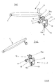

Classifications
-
- E—FIXED CONSTRUCTIONS
- E05—LOCKS; KEYS; WINDOW OR DOOR FITTINGS; SAFES
- E05C—BOLTS OR FASTENING DEVICES FOR WINGS, SPECIALLY FOR DOORS OR WINDOWS
- E05C19/00—Other devices specially designed for securing wings, e.g. with suction cups
- E05C19/02—Automatic catches, i.e. released by pull or pressure on the wing
- E05C19/022—Released by pushing in the closing direction
-
- E—FIXED CONSTRUCTIONS
- E05—LOCKS; KEYS; WINDOW OR DOOR FITTINGS; SAFES
- E05B—LOCKS; ACCESSORIES THEREFOR; HANDCUFFS
- E05B63/00—Locks or fastenings with special structural characteristics
- E05B63/24—Arrangements in which the fastening members which engage one another are mounted respectively on the wing and the frame and are both movable, e.g. for release by moving either of them
- E05B63/248—Arrangements in which the fastening members which engage one another are mounted respectively on the wing and the frame and are both movable, e.g. for release by moving either of them the striker being movable for latching, and pushed back by a member on the wing for unlatching, or vice versa
-
- E—FIXED CONSTRUCTIONS
- E05—LOCKS; KEYS; WINDOW OR DOOR FITTINGS; SAFES
- E05B—LOCKS; ACCESSORIES THEREFOR; HANDCUFFS
- E05B47/00—Operating or controlling locks or other fastening devices by electric or magnetic means
- E05B2047/0048—Circuits, feeding, monitoring
- E05B2047/005—Opening, closing of the circuit
- E05B2047/0053—Opening, closing of the circuit by operating the handle
-
- E—FIXED CONSTRUCTIONS
- E05—LOCKS; KEYS; WINDOW OR DOOR FITTINGS; SAFES
- E05B—LOCKS; ACCESSORIES THEREFOR; HANDCUFFS
- E05B47/00—Operating or controlling locks or other fastening devices by electric or magnetic means
- E05B2047/0048—Circuits, feeding, monitoring
- E05B2047/0067—Monitoring
- E05B2047/0068—Door closed
-
- E—FIXED CONSTRUCTIONS
- E05—LOCKS; KEYS; WINDOW OR DOOR FITTINGS; SAFES
- E05B—LOCKS; ACCESSORIES THEREFOR; HANDCUFFS
- E05B47/00—Operating or controlling locks or other fastening devices by electric or magnetic means
- E05B2047/0048—Circuits, feeding, monitoring
- E05B2047/0067—Monitoring
- E05B2047/0069—Monitoring bolt position
-
- E—FIXED CONSTRUCTIONS
- E05—LOCKS; KEYS; WINDOW OR DOOR FITTINGS; SAFES
- E05B—LOCKS; ACCESSORIES THEREFOR; HANDCUFFS
- E05B47/00—Operating or controlling locks or other fastening devices by electric or magnetic means
- E05B2047/0072—Operation
- E05B2047/0073—Current to unlock only
- E05B2047/0074—Current to unlock only holding means other than current (mechanical, magnetic)
-
- E—FIXED CONSTRUCTIONS
- E05—LOCKS; KEYS; WINDOW OR DOOR FITTINGS; SAFES
- E05B—LOCKS; ACCESSORIES THEREFOR; HANDCUFFS
- E05B47/00—Operating or controlling locks or other fastening devices by electric or magnetic means
- E05B47/06—Controlling mechanically-operated bolts by electro-magnetically-operated detents
- E05B47/0696—Controlling mechanically-operated bolts by electro-magnetically-operated detents locking the bolt by an electromagnet in the striker
-
- Y—GENERAL TAGGING OF NEW TECHNOLOGICAL DEVELOPMENTS; GENERAL TAGGING OF CROSS-SECTIONAL TECHNOLOGIES SPANNING OVER SEVERAL SECTIONS OF THE IPC; TECHNICAL SUBJECTS COVERED BY FORMER USPC CROSS-REFERENCE ART COLLECTIONS [XRACs] AND DIGESTS
- Y10—TECHNICAL SUBJECTS COVERED BY FORMER USPC
- Y10T—TECHNICAL SUBJECTS COVERED BY FORMER US CLASSIFICATION
- Y10T70/00—Locks
- Y10T70/50—Special application
- Y10T70/5889—For automotive vehicles
- Y10T70/5903—Hood
- Y10T70/5907—With switch
Definitions
- the invention relates to a locking method for locking a movable element, in particular a flap or a drawer, in a locking device and a locking device for a movable element, in particular a flap or a drawer, which in can be in a closed or in an open position, the Locking device a movable locking element for Locking of the movable element in its closed position having.
- Such pivoting flaps which are usually attached on one side or are articulated on one side, in particular in the automotive sector Meaning, where electromechanical locking devices for Come into play.
- flaps are, for example, tank flaps, Tailgates, glove compartments and engine compartment flaps.
- Known locking devices for such flaps are usually included DC motors, gear stages and drive elements equipped to ensure that shear forces and shear moments in the Locking mechanism can be overcome and around Reserve power in order to avoid negative influences such as temperature, To be able to compensate for corrosion, aging and wear.
- the so far The locking devices used are therefore measured in terms of technology Problem usually oversized and therefore very complex and expensive.
- the invention has for its object a locking method and to create a locking device of the type mentioned, the a reliable operation, with a simple design and cost-effective production possibility of the locking device allow.
- a locking device with the The method according to the invention is particularly low-power and wear-free operated so that the process with very small motor Components can be carried out.
- step c) the pressure must preferably be applied for a predetermined one Period of time to operate the switching element, as in this way it is ensured that a conscious and not just an accidental Applying pressure triggers the actuation of the switching element. accidental This avoids openings. Furthermore, it is favorable that the movable element in position only for a predetermined period of time is held in which when the locking device moves back locked again. This ensures that after opening the movable element, the locking element in its starting position goes back and for a new locking of the movable element in the locking device is ready. In another preferred An embodiment of the method according to the invention becomes a detection performed whether the movable element in the Locking device is locked or not, so is open. This Information is preferably forwarded to a central control point and can be evaluated and displayed there.
- a locking device for a movable element, in particular a flap or drawer that is in a closed or in a can be in the open position, the locking device being a movable locking element for locking the movable Has element in its closed position
- a switching element is provided which at Pressure is switched on the movable element that the Locking element is designed so that when pressure is exerted on the movable element a mechanical contact between the Locking element and the movable element is lifted and that the switching element is in signal connection with an actuator, that when the switching element is actuated, the actuator is switched, so that the locking element between a locking position and a Release position changes.
- the locking device one is special simple design possible because first the movable element, in particular a flap must be moved to the switching element trigger, so that the switching element then switches the actuator that the Brings locking element in the release position, so that then the flap can be swung open. Because the flap is moved first is moved so that the locking element is no longer in operative connection with the flap or a locking pin assigned to the flap, the locking element can then be moved particularly easily, without shear forces or others arising from contact with the flap Frictional forces would have to be overcome.
- the actuator can be a Motor, a gear motor, a combination of spring devices or a otherwise be a force-exerting element that enables the Locking element from the locking position to the release position and vice versa to move.
- the switching element is preferably a component the locking device and with the movable element in such a way Active connection or positioned so that when pressure is exerted on the movable element is switched.
- the movable locking element Assign spring device that the locking element in a Holds locked position and also use an actuator that is in operative connection with the locking element such that the Actuator the locking element against that of the spring device applied force in a release position.
- Locking device can be a particularly simple actuator can be used, which only has to exert a force in one direction.
- a circuit is preferred provided that the actuator for only one when the switching element is actuated predetermined period of time activated so that the locking element for the predetermined period of time is in the release position. Then that changes Locking element automatically returns to the locking position, see above that when you press the flap this directly into the locking element can snap into place.
- the switching element can be in a variety of different embodiments will be realized. For example, it can be electrical, electromagnetic or optical detection that the pivotable flap into a determined position has been brought.
- Mechanically simple and reliable is the design of the switching element as a button that from the flap is operated.
- the switching element, in particular the button is preferred with a circuit connected after a predetermined period of time Continuous pressure on the button activates the actuator emits. This way, accidental opening by accidental or accidental contact with the flap is excluded.
- the circuit assigned to the button to a predetermined Time period is set, which corresponds approximately to the predetermined period of time a circuit assigned to the actuator is set.
- the actuator is a Electromagnet trained.
- the locking device therefore comes completely without a motor and is particularly easy and inexpensive to manufacture.
- the locking device with the switching element, in particular the button, and the Actuator formed in an assembly.
- the locking device can therefore can be mounted as an element in or on the flap.
- the actuator in switching connection with the central locking system and / or another optional control unit.
- the circuit associated with the actuator is preferably designed such that that when the central locking is closed, actuation of the actuator and thus opening the lid is excluded. Only when the Central locking is an actuation of the actuator and thus an opening of the lid again.
- the switching element of the locking device is preferably positioned so that it is arranged on the flap by one Locking pin can be actuated.
- the flap is conveniently with a spring device in connection that the flap in an open Holds position so that the locking pin of the flap is closed Position is locked and pressed into this locked position.
- the one located on the flap can Locking pin actuate the button, the locking pin simultaneously leaves the locked position and the locking element of the Locking device after actuation of the button negligible small shear and friction forces is moved.
- the locking element is around one Pivot point.
- the locking element is once in a locking position and once pivotable into a release position.
- the locking element is in an end region with the Connected spring device, the locking element, in particular the end of the end region opposite the spring device Locking element pulls into the locking position.
- To the Locking element is preferably a hook element for engaging in a arranged on the flap locking pin, this Locking pin preferably also has a hook for engagement is designed in the hook element.
- the hook of the locking pin and the hook element of the locking element have defined sliding surfaces on, which allow the hook element of the locking element from the immersed locking pin of the flap to the defined one Sliding surfaces is pushed to the side until it snaps or hooks into one another.
- an additional sensor provided with which it is detected whether the movable element in the closed or in the open position.
- This is preferred as additional switch or as a second switching element or as a button formed, which is arranged next to the first switching element, wherein this second switching element triggers when the movable element in the closed position.
- the locking device also actuated first switching element that actuates the actuator triggers. In this way, additional status information won, which is evaluated and displayed in a central control can be.
- the design of this sensor can affect various others Species are done as well.
- Fig. 1 is a schematic diagram of a locking device according to the invention with a flap 1, which is designed here as a fuel cap, and one Locking device 2 shown.
- the flap 1 is on the in the figure left side pivotally attached to a bracket 3 or by one Bracket 3 rotating axis rotatable, with a spring device is provided, which the flap 1 against the direction of arrow 6 biases.
- the flap 1 has in the right end area, that is in the free pivotable end portion, a locking pin 4 with one at the end of the Locking pin arranged hook 5.
- the hook 5 is for engagement in the locking device 2, more precisely in a hook element 16 Locking element 10, designed.
- the locking device 2 has a pivotable about an axis 14 locking element 10, which here in its locking position with the reference number 10 and in its additional shown release position is marked with 10a.
- the Locking device 2 also has an electromagnet trained actuator 12 and a button 11.
- the Locking device is in a two-part housing in one Assembly arranged.
- the first housing part 18 takes the switching element 11, the locking element 10 and the actuator 12.
- the second Housing part 13 in particular surrounds the actuator 12 from above and below and forms the axis 14 for the pivoting movement of the locking element 10 out.
- the flap 1 designed as a fuel cap is in the shown swiveled position.
- the locking device 2 is the locking element again in both positions, i.e. both in the Locked position 10 and shown in the release position 10a.
- the same parts are identified by the same reference numbers.
- the sequence of movements is described with reference to the three in FIG. 3 positions explained further explained below.
- the schematic Representation according to the first position in FIG. 3 corresponds to the representation in Fig. 1, wherein the locking element 10 is in the locking position and the locking pin 4 with its hook 5 in the hook element 16 of the Locking element 10 engages.
- the locking element 10 is by a spring device 20 which at the lower end of the locking element 10, in particular below the pivot point 14, is arranged in the Locked position held.
- the second position as in FIG. 1 indicated by arrow 6, manually exerted pressure on the flap so that the Locking pin 4 is pressed down and there also as a button trained switching element 11 actuated.
- the actuator 12 actuates and pulls the Locking element in the release position marked as 10a.
- the hook element 16 of the locking element 10 in the figure pulled to the right so that the flap 1 after the manual applied pressure around the axis extending in the holder 3 upwards can pivot.
- the closing process is explained on the basis of the three representations in FIG. 4.
- the Actuator 12 is only actuated for a short time and then switches off again, so that the locking element 10 is in the locking position.
- the locking pin 4 is guided down and as can be seen in the second illustration in FIG. 4, this expresses Locking element 10 along the defined sliding surfaces to the side until the Hook 5 and the hook element 16 can snap into one another or snap in or get caught.
- the switching duration is shown in a diagram. On the x axis the time t is specified and the switching state is on the y-axis applied. In the first part of the curve shown, marked with 25, the actuator is switched off because there is a predetermined pressing duration 25 must be in which the locking pin 4 acts on the switching element 11, so that an accidental or unintentional touch from a wanted one Opening can be distinguished.
- the Actuator 12 turned on at time 26. The actuator 12 is then for one predetermined period of time 27 turned on, in which the locking element in the release position 10a. During this period the operator must Release the lid or release the pressure on the lid so that the lid can swing up.
- the predetermined length of time 25 corresponds approximately to the length of time predetermined time period 27 that the actuator is switched. This is because ultimately both periods of time adapted to a conscious human act are.
- the duration is approximately one second each.
Landscapes
- Engineering & Computer Science (AREA)
- Mechanical Engineering (AREA)
- Physics & Mathematics (AREA)
- Electromagnetism (AREA)
- Structural Engineering (AREA)
- Lock And Its Accessories (AREA)
- Drawers Of Furniture (AREA)
- Clamps And Clips (AREA)
- Connection Of Plates (AREA)
Abstract
Description
- Fig. 1:
- einen Tankdeckel mit einer Verriegelungseinrichtung in geschlossener Position;
- Fig. 2:
- einen Tankdeckel mit einer Verriegelungseinrichtung in geöffneter Position;
- Fig. 3:
- eine schematische Darstellung des Öffnungsvorgangs in drei zeitlich aufeinander folgenden Positionen;
- Fig. 4:
- eine schematische Darstellung des Schließvorgangs in drei zeitlich aufeinander folgenden Position; und
- Fig. 5:
- ein Diagramm der beim Öffnungsvorgang auftretenden Schaltdauem.
Claims (23)
- Verriegelungsverfahren zum Verriegeln eines beweglichen Elementes, insbesondere einer Klappe oder Schublade, in einer Verriegelungsvorrichtung, wobei in der Verriegelungsvorrichtung ein mit dem beweglichen Element zusammenwirkendes, bewegliches Verriegelungselement vorgesehen ist, mit folgenden Schritten beim Entriegeln:e) Ausüben eines Drucks auf das bewegliche Element in Richtung der Verriegelungsvorrichtung,f) dadurch ausgelöste Bewegung des beweglichen Elementes aus einer Verriegelungsposition mit dem Verriegelungselement heraus, so daß eine Wechselwirkung zwischen dem beweglichen Element und dem Verriegelungselement aufgehoben wird,g) durch die Druckausübung auf das bewegliche Element verursachte Betätigung eines Schaltelementes,h) durch die Betätigung des Schaltelementes ausgelöste Bewegung des beweglichen Verriegelungselementes in eine Position, in der bei Rückbewegung des beweglichen Elementes keine erneute Verriegelung erfolgt, wobei die Bewegung des beweglichen Verriegelungselementes erfolgt, während es nicht in Wechselwirkung mit dem beweglichen Element ist, so daß Reib- und Scherkräfte minimiert werden.
- Verfahren nach Anspruch 1, dadurch gekennzeichnet, daß im Schritt c) die Druckausübung für eine vorbestimmte Zeitdauer erfolgen muß, um das Schaltelement zu betätigen.
- Verfahren nach einem der Ansprüche 1 oder 2, dadurch gekennzeichnet, daß das bewegliche Element nur für eine vorbestimmte Zeitdauer in der Position gehalten wird, in der bei Rückbewegung der Verriegelungseinrichtung keine erneute Verriegelung erfolgt.
- Verfahren nach einem der vorhergehenden Ansprüche, dadurch gekennzeichnet, daß eine Detektion dahingehend durchgeführt wird, ob das bewegliche Element in der Verriegelungsvorrichtung verriegelt ist oder nicht.
- Verriegelungsvorrichtung für ein bewegliches Element, insbesondere eine Klappe oder eine Schublade, das in einer geschlossenen oder in einer geöffneten Position sein kann, wobei die Verriegelungsvorrichtung (2) ein bewegliches Verriegelungselement (10, 10a) zur Verriegelung des beweglichen Elementes (1) in dessen geschlossener Position aufweist, insbesondere zur Durchführung des Verfahrens nach einem der vorhergehenden Ansprüche,
dadurch gekennzeichnet, daß ein Schaltelement (11) vorgesehen ist, das bei Druckausübung auf das bewegliche Element (1) geschaltet wird, wobei das Verriegelungselement (10, 10a) so ausgebildet ist, daß bei Druckausübung auf das bewegliche Element (1) ein mechanischer Kontakt zwischen dem Verriegelungselement (10, 10a) und dem beweglichen Element (1) aufgehoben wird,
daß das Schaltelement (11) mit einem Aktuator (12) derart in Signalverbindung steht, daß bei Betätigung des Schaltelements (11) der Aktuator (12) geschaltet wird, so daß das Verriegelungselement (2) zwischen einer Verriegelungsposition und einer Freigabeposition wechselt. - Verriegelungsvorrichtung nach Anspruch 5, dadurch gekennzeichnet, daß das Schaltelement (11) in der Verriegelungsvorrichtung (2) vorgesehen ist und mit dem beweglichen Element (1) in Wirkverbindung ist und so positioniert ist, daß es bei Druckausübung auf das bewegliche Element (1) geschaltet wird.
- Verriegelungsvorrichtung nach einem der Ansprüche 5 oder 6, dadurch gekennzeichnet, daß dem beweglichen Verriegelungselement (10, 10a) eine Federeinrichtung (20) zugeordnet ist, die das Verriegelungselement in der Verriegelungsposition hält.
- Verriegelungsvorrichtung nach einem der Ansprüche 5 bis 7, dadurch gekennzeichnet, daß der Aktuator (12) mit dem Verriegelungselement (10, 10a) derart in Wirkverbindung steht, daß der Aktuator (12) das Verriegelungselement (10, 10a) entgegen der von der Federeinrichtung (20) aufgebrachten Kraft in die Freigabeposition (10a) bringt.
- Verriegelungsvorrichtung nach einem der Ansprüche 5 bis 8, dadurch gekennzeichnet, daß bei Betätigung des Schaltelements (11) der Aktuator (12) für eine vorbestimmte Zeitdauer aktiviert wird, so daß das Verriegelungselement (10) für die vorbestimmte Zeitdauer in der Freigabeposition (10a) ist.
- Verriegelungsvorrichtung nach einem der Ansprüche 5 bis 9, dadurch gekennzeichnet, daß das Schaltelement (11) als Taster ausgebildet ist.
- Verriegelungsvorrichtung nach einem der Ansprüche 5 bis 10, dadurch gekennzeichnet, daß der Taster mit einer Schaltung verbunden ist, die erst nach einer vorbestimmten Zeitdauer anhaltenden Drucks auf den Taster (11) ein Aktivierungssignal für den Aktuator (12) abgibt.
- Verriegelungsvorrichtung nach Anspruch 11, dadurch gekennzeichnet, daß die dem Taster (11) zugeordnete Schaltung auf eine vorbestimmte Zeitdauer eingestellt ist, die etwa der vorbestimmten Zeitdauer entspricht, auf die eine dem Aktuator (12) zugeordnete Schaltung eingestellt ist.
- Verriegelungsvorrichtung nach einem der Ansprüche 5 bis 12, dadurch gekennzeichnet, daß die Verriegelungseinrichtung (2) mit dem Verriegelungselement (10), der Federeinrichtung (20), dem Schaltelement (11) und dem Aktuator (12) in einer Baugruppe ausgebildet ist.
- Verriegelungsvorrichtung nach einem der Ansprüche 5 bis 13, dadurch gekennzeichnet, daß der Aktuator (12) in Schaltverbindung mit einer Zentralverriegelung ist.
- Verriegelungsvorrichtung nach einem der Ansprüche 5 bis 14, dadurch gekennzeichnet, daß der Taster (11) so positioniert ist, daß er von einem an dem beweglichen Element (1) angeordneten Verriegelungsstift (4) betätigbar ist.
- Verriegelungsvorrichtung nach einem der Ansprüche 5 bis 15, dadurch gekennzeichnet, daß das bewegliche Element (1) mit einer Federeinrichtung in Verbindung steht, die das bewegliche Element in eine geöffnete Position vorspannt.
- Schließvorrichtung nach einem der Ansprüche 5 bis 16, dadurch gekennzeichnet, daß das Verriegelungselement (10) um einen Drehpunkt (14) schwenkbar ist.
- Schließvorrichtung nach einem der Ansprüche 5 bis 17, dadurch gekennzeichnet, daß das Verriegelungselement (10) in einem Endbereich mit der Federeinrichtung (20) verbunden ist.
- Schließvorrichtung nach einem der Ansprüche 5 bis 18, dadurch gekennzeichnet, daß das Verriegelungselement (10) in einem freien Endbereich ein Hakenelement (16) aufweist.
- Schließvorrichtung nach einem der Ansprüche 5 bis 19, dadurch gekennzeichnet, daß das Hakenelement (16) zum Eingriff in einen an dem beweglichen Element (1) befestigten Verriegelungsstift (4) ausgelegt ist.
- Schließvorrichtung nach einem der Ansprüche 15 bis 20, dadurch gekennzeichnet, daß der Verriegelungsstift (4) in seinem Endbereich einen Haken (5) aufweist, der über definierte Gleitflächen am Hakenelement (16) des Verriegelungselements (10) entlang gleitet und mit diesem verhakt.
- Schließvorrichtung nach einem der Ansprüche 5 bis 21, dadurch gekennzeichnet, ein Sensor vorgesehen ist, der detektiert, ob das bewegliche Verriegelungselement in der geschlossenen oder der geöffneten Position ist.
- Verriegelungsvorrichtung nach Anspruch 22, dadurch gekennzeichnet, daß der Sensor als zweiter Taster oder Schalter ausgebildet ist, der zusätzlich zu dem Schaltelement (11) vorgesehen ist und ausgelöst ist, wenn das bewegliche Element in der verriegelten Ruheposition ist, während das Schaltelement (11) nur bei einer zusätzlichen Druckausübung auf das bewegliche Element ausgelöst wird.
Applications Claiming Priority (2)
| Application Number | Priority Date | Filing Date | Title |
|---|---|---|---|
| DE2003126416 DE10326416A1 (de) | 2003-06-12 | 2003-06-12 | Verriegelungsverfahren und Verriegelungsvorrichtung für ein bewegliches Element, insbesondere eine Klappe |
| DE10326416 | 2003-06-12 |
Publications (2)
| Publication Number | Publication Date |
|---|---|
| EP1486634A1 true EP1486634A1 (de) | 2004-12-15 |
| EP1486634B1 EP1486634B1 (de) | 2008-12-10 |
Family
ID=33185754
Family Applications (1)
| Application Number | Title | Priority Date | Filing Date |
|---|---|---|---|
| EP20040012548 Expired - Lifetime EP1486634B1 (de) | 2003-06-12 | 2004-05-27 | Verriegelungsverfahren und Verriegelungsvorrichtung für ein bewegliches Element, insbesondere eine Klappe |
Country Status (4)
| Country | Link |
|---|---|
| US (1) | US20040255626A1 (de) |
| EP (1) | EP1486634B1 (de) |
| AT (1) | ATE417172T1 (de) |
| DE (2) | DE10326416A1 (de) |
Cited By (1)
| Publication number | Priority date | Publication date | Assignee | Title |
|---|---|---|---|---|
| CN111779389A (zh) * | 2020-07-15 | 2020-10-16 | 陈丹丹 | 一种防盗用居民单元楼门锁 |
Families Citing this family (5)
| Publication number | Priority date | Publication date | Assignee | Title |
|---|---|---|---|---|
| US7051560B2 (en) * | 2004-04-07 | 2006-05-30 | Dynalock Corporation | Electromagnetic door security system |
| DE102007000899B3 (de) * | 2007-11-14 | 2009-05-14 | Faurecia Innenraum Systeme Gmbh | Verschluss für ein Staufach eines Kraftfahrzeugs |
| DE102011008992A1 (de) * | 2011-01-20 | 2012-07-26 | GM Global Technology Operations LLC (n. d. Ges. d. Staates Delaware) | Verschlussvorrichtung |
| DE202014001751U1 (de) * | 2014-02-24 | 2015-05-27 | GM Global Technology Operations LLC (n. d. Ges. d. Staates Delaware) | Kraftfahrzeug-Klappenanordnung |
| DE102023120638A1 (de) | 2023-08-03 | 2025-02-06 | Brose Schließsysteme GmbH & Co. Kommanditgesellschaft | Verriegelung einer Fronthaube |
Citations (4)
| Publication number | Priority date | Publication date | Assignee | Title |
|---|---|---|---|---|
| US5490698A (en) * | 1994-07-05 | 1996-02-13 | Dezso; Paul M. | Door locking system |
| US5664811A (en) * | 1995-04-12 | 1997-09-09 | Lectron Products, Inc. | Fuel filler door actuator assembly with integral kick-out spring |
| DE19736561A1 (de) * | 1997-08-22 | 1999-03-04 | Daimler Benz Ag | Verschlußklappe für Behältnisse wie Ablagefächer, Aschenbecher und dergleichen, insbesondere für Kraftfahrzeuge, sowie Verfahren zum Öffnen einer Verschlußklappe |
| US5901991A (en) * | 1996-05-21 | 1999-05-11 | Robert Bosch Gmbh | Process for triggering an electrically actuated motor vehicle door lock or the like |
Family Cites Families (10)
| Publication number | Priority date | Publication date | Assignee | Title |
|---|---|---|---|---|
| DE1900508U (de) * | 1964-06-19 | 1964-09-10 | Theodor Dr Ing Vogel | Schnappverschluss fuer schiebefenster. |
| US4068872A (en) * | 1976-02-11 | 1978-01-17 | Smith Charles V | Latched cabinet structure |
| GB2028412B (en) * | 1978-08-19 | 1982-06-16 | Ford Motor Co | Vehicle engine cover latch |
| DE8105711U1 (de) * | 1981-02-28 | 1983-11-10 | Häfele KG, 7270 Nagold | Schnappverschluss fuer schranktueren oder dgl. |
| DE19961246A1 (de) * | 1999-05-18 | 2001-06-21 | Huf Huelsbeck & Fuerst Gmbh | Vorrichtung zum Wirksamsetzen einer Öffnungs- und/oder einer Schließhilfe für verschließbare Teile an Fahrzeugen, wie Klappen, Türen od. dgl. |
| DE19943083C2 (de) * | 1999-09-09 | 2003-11-20 | Kiekert Ag | Schloßhalter für einen Kraftfahrzeugtürverschluß |
| JP4474740B2 (ja) * | 2000-06-15 | 2010-06-09 | アイシン精機株式会社 | 車両用ドアラッチ操作制御装置 |
| DE10133092A1 (de) * | 2001-07-11 | 2003-01-30 | Huf Huelsbeck & Fuerst Gmbh | Schloß, insbesondere für Kraftfahrzeugtüren, -klappen od. dgl. |
| TW577619U (en) * | 2002-10-18 | 2004-02-21 | Lite On It Corp | Outer lid locking and securing device of lid-lifting type CD drive |
| TWI262242B (en) * | 2004-05-11 | 2006-09-21 | Nifco Inc | Cap opening/closing mechanism |
-
2003
- 2003-06-12 DE DE2003126416 patent/DE10326416A1/de not_active Withdrawn
-
2004
- 2004-05-27 EP EP20040012548 patent/EP1486634B1/de not_active Expired - Lifetime
- 2004-05-27 DE DE200450008622 patent/DE502004008622D1/de not_active Expired - Lifetime
- 2004-05-27 AT AT04012548T patent/ATE417172T1/de not_active IP Right Cessation
- 2004-06-10 US US10/868,442 patent/US20040255626A1/en not_active Abandoned
Patent Citations (4)
| Publication number | Priority date | Publication date | Assignee | Title |
|---|---|---|---|---|
| US5490698A (en) * | 1994-07-05 | 1996-02-13 | Dezso; Paul M. | Door locking system |
| US5664811A (en) * | 1995-04-12 | 1997-09-09 | Lectron Products, Inc. | Fuel filler door actuator assembly with integral kick-out spring |
| US5901991A (en) * | 1996-05-21 | 1999-05-11 | Robert Bosch Gmbh | Process for triggering an electrically actuated motor vehicle door lock or the like |
| DE19736561A1 (de) * | 1997-08-22 | 1999-03-04 | Daimler Benz Ag | Verschlußklappe für Behältnisse wie Ablagefächer, Aschenbecher und dergleichen, insbesondere für Kraftfahrzeuge, sowie Verfahren zum Öffnen einer Verschlußklappe |
Cited By (1)
| Publication number | Priority date | Publication date | Assignee | Title |
|---|---|---|---|---|
| CN111779389A (zh) * | 2020-07-15 | 2020-10-16 | 陈丹丹 | 一种防盗用居民单元楼门锁 |
Also Published As
| Publication number | Publication date |
|---|---|
| DE10326416A1 (de) | 2004-12-30 |
| US20040255626A1 (en) | 2004-12-23 |
| EP1486634B1 (de) | 2008-12-10 |
| ATE417172T1 (de) | 2008-12-15 |
| DE502004008622D1 (de) | 2009-01-22 |
Similar Documents
| Publication | Publication Date | Title |
|---|---|---|
| EP2313671B1 (de) | Wählhebel mit aktuatorischem positionswechsel | |
| EP1740752B1 (de) | Verschluss für ein hausgerät | |
| DE10207945A1 (de) | Fahrzeugtürschloss | |
| DE1790340A1 (de) | Zeitschaltgeraet | |
| DE10029841B4 (de) | Verschlußvorrichtung für eine Fahrzeugtür | |
| DE19601228A1 (de) | Vorrichtung zum Verriegeln der Tür einer Wasch- oder Spülmaschine | |
| EP1632626A1 (de) | Kraftfahrzeugschloss | |
| WO2019063039A1 (de) | Kraftfahrzeugschloss für ein bewegliches teil eines kraftfahrzeugs | |
| DE10137800A1 (de) | Schliessvorrichtung, insbesondere für eine Kofferraumklappe | |
| EP1486634B1 (de) | Verriegelungsverfahren und Verriegelungsvorrichtung für ein bewegliches Element, insbesondere eine Klappe | |
| DE3117040A1 (de) | Betaetigungsvorrichtung fuer ein kipp- und schiebedach eines kraftfahrzeugs | |
| DE19824515C2 (de) | Schaltelement zum Betätigen eines öffnungsfähigen Fahrzeugdachs | |
| DE4445339A1 (de) | Vorrichtung für das Schalten eines Elektromotors, insbesondere zum Abbremsen eines Elektrowerkzeuges | |
| DE4301961A1 (de) | Verfahren und Vorrichtung zum Betätigen von Einbaukomponenten in Kraftfahrzeugen | |
| EP3652765B1 (de) | Mechanischer schalter | |
| EP0685914B1 (de) | Einfahrbares Schaltgerät mit einer Anzeigevorrichtung für die Stellung des Schaltgerätes | |
| DE2700272B2 (de) | Betätigungsmechanismus für einen Schalter | |
| DE19519999C2 (de) | Anordnung zur Sperrung oder Freigabe der Betätigung eines Leistungsschalters | |
| DE102013013176A1 (de) | Vorrichtung zum Öffnen eines Verschlusselementes eines Fahrzeugs | |
| EP0940281B1 (de) | Verfahren zum Steuern eines fremdkraftbetätigt zu öffnenden Daches eines Fahrzeuges mit einer Betätigungseinrichtung | |
| EP0058147B1 (de) | Lochschieber, insbesondere für Luftheizungen | |
| EP0688031B1 (de) | Leistungsschalter mit einem Anzeigeorgan für den Zustand eines Energiespeichers | |
| DE2900415C3 (de) | Rückstelleinrichtung für mechanische Rollenzählwerke | |
| DE102016214681B4 (de) | Betätigungsvorrichtung für ein Kraftfahrzeug | |
| DE19623674B4 (de) | Schaltschütz |
Legal Events
| Date | Code | Title | Description |
|---|---|---|---|
| PUAI | Public reference made under article 153(3) epc to a published international application that has entered the european phase |
Free format text: ORIGINAL CODE: 0009012 |
|
| AK | Designated contracting states |
Kind code of ref document: A1 Designated state(s): AT BE BG CH CY CZ DE DK EE ES FI FR GB GR HU IE IT LI LU MC NL PL PT RO SE SI SK TR |
|
| AX | Request for extension of the european patent |
Extension state: AL HR LT LV MK |
|
| 17P | Request for examination filed |
Effective date: 20050414 |
|
| AKX | Designation fees paid |
Designated state(s): AT BE BG CH CY CZ DE DK EE ES FI FR GB GR HU IE IT LI LU MC NL PL PT RO SE SI SK TR |
|
| GRAP | Despatch of communication of intention to grant a patent |
Free format text: ORIGINAL CODE: EPIDOSNIGR1 |
|
| GRAS | Grant fee paid |
Free format text: ORIGINAL CODE: EPIDOSNIGR3 |
|
| GRAA | (expected) grant |
Free format text: ORIGINAL CODE: 0009210 |
|
| AK | Designated contracting states |
Kind code of ref document: B1 Designated state(s): AT BE BG CH CY CZ DE DK EE ES FI FR GB GR HU IE IT LI LU MC NL PL PT RO SE SI SK TR |
|
| REG | Reference to a national code |
Ref country code: GB Ref legal event code: FG4D Free format text: NOT ENGLISH |
|
| REG | Reference to a national code |
Ref country code: CH Ref legal event code: EP |
|
| REG | Reference to a national code |
Ref country code: IE Ref legal event code: FG4D Free format text: LANGUAGE OF EP DOCUMENT: GERMAN |
|
| REF | Corresponds to: |
Ref document number: 502004008622 Country of ref document: DE Date of ref document: 20090122 Kind code of ref document: P |
|
| PG25 | Lapsed in a contracting state [announced via postgrant information from national office to epo] |
Ref country code: NL Free format text: LAPSE BECAUSE OF FAILURE TO SUBMIT A TRANSLATION OF THE DESCRIPTION OR TO PAY THE FEE WITHIN THE PRESCRIBED TIME-LIMIT Effective date: 20081210 Ref country code: FI Free format text: LAPSE BECAUSE OF FAILURE TO SUBMIT A TRANSLATION OF THE DESCRIPTION OR TO PAY THE FEE WITHIN THE PRESCRIBED TIME-LIMIT Effective date: 20081210 Ref country code: PL Free format text: LAPSE BECAUSE OF FAILURE TO SUBMIT A TRANSLATION OF THE DESCRIPTION OR TO PAY THE FEE WITHIN THE PRESCRIBED TIME-LIMIT Effective date: 20081210 Ref country code: SI Free format text: LAPSE BECAUSE OF FAILURE TO SUBMIT A TRANSLATION OF THE DESCRIPTION OR TO PAY THE FEE WITHIN THE PRESCRIBED TIME-LIMIT Effective date: 20081210 |
|
| NLV1 | Nl: lapsed or annulled due to failure to fulfill the requirements of art. 29p and 29m of the patents act | ||
| REG | Reference to a national code |
Ref country code: IE Ref legal event code: FD4D |
|
| PG25 | Lapsed in a contracting state [announced via postgrant information from national office to epo] |
Ref country code: ES Free format text: LAPSE BECAUSE OF FAILURE TO SUBMIT A TRANSLATION OF THE DESCRIPTION OR TO PAY THE FEE WITHIN THE PRESCRIBED TIME-LIMIT Effective date: 20090321 Ref country code: RO Free format text: LAPSE BECAUSE OF FAILURE TO SUBMIT A TRANSLATION OF THE DESCRIPTION OR TO PAY THE FEE WITHIN THE PRESCRIBED TIME-LIMIT Effective date: 20081210 Ref country code: EE Free format text: LAPSE BECAUSE OF FAILURE TO SUBMIT A TRANSLATION OF THE DESCRIPTION OR TO PAY THE FEE WITHIN THE PRESCRIBED TIME-LIMIT Effective date: 20081210 Ref country code: BG Free format text: LAPSE BECAUSE OF FAILURE TO SUBMIT A TRANSLATION OF THE DESCRIPTION OR TO PAY THE FEE WITHIN THE PRESCRIBED TIME-LIMIT Effective date: 20090310 Ref country code: IE Free format text: LAPSE BECAUSE OF FAILURE TO SUBMIT A TRANSLATION OF THE DESCRIPTION OR TO PAY THE FEE WITHIN THE PRESCRIBED TIME-LIMIT Effective date: 20081210 |
|
| PG25 | Lapsed in a contracting state [announced via postgrant information from national office to epo] |
Ref country code: SE Free format text: LAPSE BECAUSE OF FAILURE TO SUBMIT A TRANSLATION OF THE DESCRIPTION OR TO PAY THE FEE WITHIN THE PRESCRIBED TIME-LIMIT Effective date: 20090310 Ref country code: PT Free format text: LAPSE BECAUSE OF FAILURE TO SUBMIT A TRANSLATION OF THE DESCRIPTION OR TO PAY THE FEE WITHIN THE PRESCRIBED TIME-LIMIT Effective date: 20090511 Ref country code: CZ Free format text: LAPSE BECAUSE OF FAILURE TO SUBMIT A TRANSLATION OF THE DESCRIPTION OR TO PAY THE FEE WITHIN THE PRESCRIBED TIME-LIMIT Effective date: 20081210 |
|
| PG25 | Lapsed in a contracting state [announced via postgrant information from national office to epo] |
Ref country code: SK Free format text: LAPSE BECAUSE OF FAILURE TO SUBMIT A TRANSLATION OF THE DESCRIPTION OR TO PAY THE FEE WITHIN THE PRESCRIBED TIME-LIMIT Effective date: 20081210 |
|
| PLBE | No opposition filed within time limit |
Free format text: ORIGINAL CODE: 0009261 |
|
| STAA | Information on the status of an ep patent application or granted ep patent |
Free format text: STATUS: NO OPPOSITION FILED WITHIN TIME LIMIT |
|
| PG25 | Lapsed in a contracting state [announced via postgrant information from national office to epo] |
Ref country code: DK Free format text: LAPSE BECAUSE OF FAILURE TO SUBMIT A TRANSLATION OF THE DESCRIPTION OR TO PAY THE FEE WITHIN THE PRESCRIBED TIME-LIMIT Effective date: 20081210 |
|
| 26N | No opposition filed |
Effective date: 20090911 |
|
| BERE | Be: lapsed |
Owner name: HELLA KGAA HUECK & CO. Effective date: 20090531 |
|
| PG25 | Lapsed in a contracting state [announced via postgrant information from national office to epo] |
Ref country code: MC Free format text: LAPSE BECAUSE OF NON-PAYMENT OF DUE FEES Effective date: 20090531 |
|
| REG | Reference to a national code |
Ref country code: CH Ref legal event code: PL |
|
| GBPC | Gb: european patent ceased through non-payment of renewal fee |
Effective date: 20090527 |
|
| PG25 | Lapsed in a contracting state [announced via postgrant information from national office to epo] |
Ref country code: LI Free format text: LAPSE BECAUSE OF NON-PAYMENT OF DUE FEES Effective date: 20090531 Ref country code: CH Free format text: LAPSE BECAUSE OF NON-PAYMENT OF DUE FEES Effective date: 20090531 |
|
| REG | Reference to a national code |
Ref country code: FR Ref legal event code: ST Effective date: 20100129 |
|
| PG25 | Lapsed in a contracting state [announced via postgrant information from national office to epo] |
Ref country code: FR Free format text: LAPSE BECAUSE OF NON-PAYMENT OF DUE FEES Effective date: 20090602 |
|
| PG25 | Lapsed in a contracting state [announced via postgrant information from national office to epo] |
Ref country code: GB Free format text: LAPSE BECAUSE OF NON-PAYMENT OF DUE FEES Effective date: 20090527 |
|
| PG25 | Lapsed in a contracting state [announced via postgrant information from national office to epo] |
Ref country code: BE Free format text: LAPSE BECAUSE OF NON-PAYMENT OF DUE FEES Effective date: 20090531 |
|
| PG25 | Lapsed in a contracting state [announced via postgrant information from national office to epo] |
Ref country code: AT Free format text: LAPSE BECAUSE OF NON-PAYMENT OF DUE FEES Effective date: 20090527 |
|
| PG25 | Lapsed in a contracting state [announced via postgrant information from national office to epo] |
Ref country code: GR Free format text: LAPSE BECAUSE OF FAILURE TO SUBMIT A TRANSLATION OF THE DESCRIPTION OR TO PAY THE FEE WITHIN THE PRESCRIBED TIME-LIMIT Effective date: 20090311 |
|
| PG25 | Lapsed in a contracting state [announced via postgrant information from national office to epo] |
Ref country code: IT Free format text: LAPSE BECAUSE OF FAILURE TO SUBMIT A TRANSLATION OF THE DESCRIPTION OR TO PAY THE FEE WITHIN THE PRESCRIBED TIME-LIMIT Effective date: 20081210 |
|
| PG25 | Lapsed in a contracting state [announced via postgrant information from national office to epo] |
Ref country code: LU Free format text: LAPSE BECAUSE OF NON-PAYMENT OF DUE FEES Effective date: 20090527 |
|
| PG25 | Lapsed in a contracting state [announced via postgrant information from national office to epo] |
Ref country code: HU Free format text: LAPSE BECAUSE OF FAILURE TO SUBMIT A TRANSLATION OF THE DESCRIPTION OR TO PAY THE FEE WITHIN THE PRESCRIBED TIME-LIMIT Effective date: 20090611 |
|
| PG25 | Lapsed in a contracting state [announced via postgrant information from national office to epo] |
Ref country code: TR Free format text: LAPSE BECAUSE OF FAILURE TO SUBMIT A TRANSLATION OF THE DESCRIPTION OR TO PAY THE FEE WITHIN THE PRESCRIBED TIME-LIMIT Effective date: 20081210 |
|
| PG25 | Lapsed in a contracting state [announced via postgrant information from national office to epo] |
Ref country code: CY Free format text: LAPSE BECAUSE OF FAILURE TO SUBMIT A TRANSLATION OF THE DESCRIPTION OR TO PAY THE FEE WITHIN THE PRESCRIBED TIME-LIMIT Effective date: 20081210 |
|
| PGFP | Annual fee paid to national office [announced via postgrant information from national office to epo] |
Ref country code: DE Payment date: 20170523 Year of fee payment: 14 |
|
| REG | Reference to a national code |
Ref country code: DE Ref legal event code: R082 Ref document number: 502004008622 Country of ref document: DE Representative=s name: PATENTANWAELTE JABBUSCH SIEKMANN & WASILJEFF, DE Ref country code: DE Ref legal event code: R081 Ref document number: 502004008622 Country of ref document: DE Owner name: HELLA GMBH & CO. KGAA, DE Free format text: FORMER OWNER: HELLA KGAA HUECK & CO., 59557 LIPPSTADT, DE |
|
| REG | Reference to a national code |
Ref country code: DE Ref legal event code: R119 Ref document number: 502004008622 Country of ref document: DE |
|
| PG25 | Lapsed in a contracting state [announced via postgrant information from national office to epo] |
Ref country code: DE Free format text: LAPSE BECAUSE OF NON-PAYMENT OF DUE FEES Effective date: 20181201 |