EP1486594A1 - Fadenabzugsdüse - Google Patents
Fadenabzugsdüse Download PDFInfo
- Publication number
- EP1486594A1 EP1486594A1 EP03013005A EP03013005A EP1486594A1 EP 1486594 A1 EP1486594 A1 EP 1486594A1 EP 03013005 A EP03013005 A EP 03013005A EP 03013005 A EP03013005 A EP 03013005A EP 1486594 A1 EP1486594 A1 EP 1486594A1
- Authority
- EP
- European Patent Office
- Prior art keywords
- nozzle
- thread
- thread take
- spinning
- grooves
- Prior art date
- Legal status (The legal status is an assumption and is not a legal conclusion. Google has not performed a legal analysis and makes no representation as to the accuracy of the status listed.)
- Granted
Links
- 239000000919 ceramic Substances 0.000 claims abstract description 4
- 239000011324 bead Substances 0.000 claims description 18
- 238000007383 open-end spinning Methods 0.000 claims description 16
- 238000004512 die casting Methods 0.000 claims 1
- 238000001746 injection moulding Methods 0.000 claims 1
- 238000009987 spinning Methods 0.000 description 31
- 239000000835 fiber Substances 0.000 description 5
- 238000004519 manufacturing process Methods 0.000 description 5
- 239000000463 material Substances 0.000 description 5
- 230000015572 biosynthetic process Effects 0.000 description 4
- 230000000694 effects Effects 0.000 description 3
- 229920000742 Cotton Polymers 0.000 description 2
- 230000001419 dependent effect Effects 0.000 description 2
- 229910018072 Al 2 O 3 Inorganic materials 0.000 description 1
- 229910000831 Steel Inorganic materials 0.000 description 1
- 230000032683 aging Effects 0.000 description 1
- 238000010276 construction Methods 0.000 description 1
- 239000000428 dust Substances 0.000 description 1
- 238000002347 injection Methods 0.000 description 1
- 239000007924 injection Substances 0.000 description 1
- 239000000203 mixture Substances 0.000 description 1
- 230000003647 oxidation Effects 0.000 description 1
- 238000007254 oxidation reaction Methods 0.000 description 1
- 229910052574 oxide ceramic Inorganic materials 0.000 description 1
- 238000005498 polishing Methods 0.000 description 1
- 229920000728 polyester Polymers 0.000 description 1
- 238000003825 pressing Methods 0.000 description 1
- 230000000452 restraining effect Effects 0.000 description 1
- 239000010959 steel Substances 0.000 description 1
- 238000011144 upstream manufacturing Methods 0.000 description 1
Images

Classifications
-
- D—TEXTILES; PAPER
- D01—NATURAL OR MAN-MADE THREADS OR FIBRES; SPINNING
- D01H—SPINNING OR TWISTING
- D01H4/00—Open-end spinning machines or arrangements for imparting twist to independently moving fibres separated from slivers; Piecing arrangements therefor; Covering endless core threads with fibres by open-end spinning techniques
- D01H4/40—Removing running yarn from the yarn forming region, e.g. using tubes
Definitions
- the invention relates to a thread take-off nozzle for a Open-end rotor spinning device according to the preamble of Claim 1.
- Thread take-off nozzles for open-end rotor spinning devices have been around since state of the art and in various embodiments known.
- the problem with open-end rotor spinning devices is that the real yarn twist introduced by the rotation of the spinning rotor does not run evenly into the yarn being produced. This means that the real yarn twist is increasingly applied to the piece of yarn that is located between the thread take-off nozzle and the thread take-off device of the open-end rotor spinning device. In contrast, the real yarn twist often runs into the yarn piece in front of the thread take-off nozzle only very incompletely.
- the material or the Surface structures are numerous in many thread take-off nozzles different embodiments are known.
- DE-OS 25 44 721, DE 33 44 741 A1 or the EP 0 422 615 B1 describe thread draw-off nozzles which have notch-like depressions in the region of the thread inlet zone.
- the thread take-off nozzle is made of an oxide ceramic material and has a roughness depth of 0.2 to 0.7 ⁇ m in the area of the thread inlet funnel. Notches, which can have different notch opening angles, are also arranged in the region of the thread inlet zone.
- the thread take-off nozzles described in DE 33 44 741 A1 have an exchangeable thread inlet funnel drawn from sheet steel and subsequently hardened.
- the thread feed hopper has either notches or protruding beads. The notches can also be positioned in two ring-like arrangements, which lie one behind the other in the direction of the thread.
- EP 0 422 615 B1 relates to a thread draw-off nozzle which has notches in the area of the thread entry zone and protrusions in the area of its thread take-off channel.
- the notches are said to improve the spinning stability of the open-end spinning device, while the projections in the thread take-off channel are used to produce a particularly hairy yarn.
- a thread draw-off nozzle is known from CH-PS 535 294, which has both ring-shaped notches in the region of the mouth funnel and notches which are arranged orthogonally to these ring-shaped notches. This means that with this thread take-off nozzle, differently arranged notches overlap and form a multitude of relatively aggressive abutments for the rotating thread.
- This known thread draw-off nozzle has not proven itself in practice and has not been able to establish itself on the market.
- DE 37 07 526 A1, DE 42 24 632 A1 or EP 0 220 546 A1 relates, for example, to thread take-off nozzles designed in this way.
- the spiral structure can, for example, as in the DE 37 07 526 A1 or EP 0 220 546 A1 web-like or bulge-like elevations are formed preferably over the entire thread inlet zone of the Thread take-off nozzle up to the start of the thread take-off channel Extend the thread take-off nozzle.
- DE 42 24 632 A1 also describes a thread draw-off nozzle with a spiral structure.
- the thread draw-off nozzle has spirally running surfaces which are straight with respect to the thread running direction and which are arranged inclined at an angle in order to achieve thread deflection points.
- Such a spiral / notch nozzle is for example in the DE 197 38 382 A1 described.
- a spiral structure for holding back the real yarn twist is arranged in the mouth area and notches are additionally positioned in the input area of the thread take-off channel.
- the thread draw-off nozzles according to DE 197 38 382 A1 have proven themselves very well in practice, which means that they can be used to produce yarns of outstanding quality, in particular when spinning cotton but also of polyester / cotton blends.
- spiral / notch nozzles which are proven per se, are very expensive to produce. This means that a relatively complex and overall very expensive tool is necessary to manufacture the spiral structure in the mouth area of the thread take-off nozzles.
- a disadvantage of these thread take-off nozzles is also that spiral structure towards the edge of the thread take-off nozzle leaks, which leads to that during spinning constantly the distance between the thread formation zone in the groove of the Spinning rotor and the spiral structure to restrain the real yarn twist changes.
- the present invention is based on the aforementioned prior art hence the task of further improving To create thread take-off nozzle.
- the thread draw-off nozzles according to the invention have the advantage, among other things, that on the one hand the complexity of the tools required for their production is significantly smaller than that of thread draw-off nozzles with a spiral structure and that on the other hand production with a significantly lower reject rate is possible. This means that the thread take-off nozzles according to the invention can be manufactured significantly more cost-effectively than the spiral / notch nozzles known and proven per se.
- the arrangement according to the invention of circular beads or grooves of different diameters in the area of the mouth funnel of the thread take-off nozzle also ensures that there is always a constant distance between the thread formation zone in the spinning rotor and the structure for restraining the real yarn twist, which has an advantageous effect on the yarn quality.
- the circular beads or grooves are preferably how set out in claim 2, arranged concentrically.
- the beads or grooves the surface pressure on the thread increases and is therefore effective prevents too much real yarn twist from the critical area can leave in front of the thread take-off nozzle.
- the surface of such a thread take-off nozzle is advantageously polished at least in the region of the mouth funnel of the nozzle.
- the thread take-off nozzles as in Claim 8 set forth, manufactured by injection or pressing.
- These known and proven manufacturing processes enable especially with larger quantities, one cost-effective production, the individual components in highest precision can be manufactured.
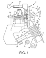
- the open-end rotor spinning device shown schematically in FIG. 1 bears the overall reference number 1.
- Such spinning devices each have a rotor housing 2 in which the spinning cup of a spinning rotor 3 rotates at high speed.
- the spinning rotor 3 is supported with its rotor shaft 4 in the bearing gussets of a so-called support disk bearing 5 and is driven by a machine-long tangential belt 6, which is acted upon by a pressure roller 7.
- the rotor shaft 4 is axially fixed, for example, by means of a permanent magnetic axial bearing 18.
- the rotor housing 2 which is open towards the front, is closed during the Spinning operation by a pivotably mounted cover element 8 closable.
- Rotor housing 2 is also a corresponding one Suction line 10 connected to a vacuum source 11, the the spinning vacuum required in the rotor housing 2 is generated.
- a fader tape release device is integrated in the cover element 8, which is rotatably supported to a limited extent about a pivot axis 16. That is to say, the cover element 8 has an opening roller housing 17 and rear-side bearing brackets 19, 20 for mounting an opening roller 21 or a sliver feed cylinder 22.
- the opening roller 21 is driven via a rotating, machine-long tangential belt 24, which acts on a whorl 23 of the opening roller 21, while the drive of the sliver feed cylinder 22 is preferably carried out via a machine-long drive shaft 25 or a worm gear (not shown).
- the individual fibers 28 released by the opening roller 21 from a feed fiber band (not shown) are fed into the spinning rotor 3 via the fiber guide channel 14 and, as is customary in open-end rotor spinning devices, are first collected in the region of the rotor groove 27 of the spinning rotor 3.
- the individual fibers 28 are then spun into a thread 29 which is drawn off via the thread take-off nozzle 13.
- the thread take-off speed with which the new thread 29 can be drawn in the direction A from the open-end spinning device 1 is dependent on various factors, such as the rotor speed, the desired yarn rotation, etc., and can be set via a thread take-off device 35.
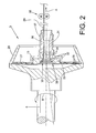
- the thread take-off nozzle 13 is, preferably non-detachably, fixed in a nozzle holder 36, which is connected to the channel plate adapter 12, for example, via an external thread 37 or a (not shown) magnetic connection.
- the thread draw-off nozzle 13 has a coaxially arranged structure 30 in the region of its mouth funnel 38.
- This coaxially arranged structure 30 is formed either by circular beads or by comparable annular grooves 32 of different diameters. It is up to the observer to consider whether these are beads or grooves.
- Figure 2 shows a thread take-off nozzle 13, the coaxial arranged structure 30 by means of circular beads or grooves 32 different diameter is formed, which is in the range of Mouth funnel 38 are arranged axially spaced.
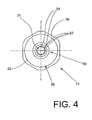
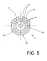
- the exemplary embodiment according to FIG. 3 shows a coaxially arranged structure 30 which consists of a plurality of concentrically arranged beads or grooves 32 of different diameters. These concentrically arranged beads or grooves 32 preferably extend from the area of the outer edge 33 of the thread draw-off nozzle 13 to the beginning of the funnel-like inlet area of the thread draw-off nozzle 13.
- notches 34 are additionally arranged in each case.
- the notches 34 are in the present embodiments Four notches 34 each are shown, for example in the entrance area of the thread take-off channel 31 Thread take-off nozzle 13.
- the thread take-off nozzles 13 according to the invention are preferably made of a high-performance ceramic, for example Al 2 O 3 .
- This material is highly stable even under point loads and largely resistant to aging (oxidation).
- this oxidic hard material is characterized by good thermal conductivity.
- the above-described coaxially arranged structures 30 of the thread draw-off nozzle 13 and the formation of the notches are expressly not limited to the exemplary embodiments shown in the figures with regard to their exact embodiment. This means that the beads or grooves can differ from the exemplary embodiments both in terms of their number and in terms of their width or height. Likewise, depending on the yarn material to be processed, the notches can be made longer or shorter, wider or narrower, and deeper or flatter, for example.
Landscapes
- Engineering & Computer Science (AREA)
- Mechanical Engineering (AREA)
- Textile Engineering (AREA)
- Spinning Or Twisting Of Yarns (AREA)
Abstract
Description
Das heißt, die echte Garndrehung wird verstärkt auf das Garnstück aufgebracht, das sich jeweils zwischen der Fadenabzugsdüse und der Fadenabzugseinrichtung der Offenend-Rotorspinnvorrichtung befindet.
In das vor der Fadenabzugsdüse befindliche Garnstück läuft die echte Garndrehung hingegen oft nur sehr unvollständig ein.
EP 0 422 615 B1 beschreiben beispielsweise Fadenabzugsdüsen, die im Bereich der Fadeneinlaufzone kerbenartige Vertiefungen besitzen.
Gemäß der DE-OS 25 44 721 ist die Fadenabzugsdüse dabei aus einem oxydkeramischen Werkstoff gefertigt und weist im Bereich des Fadeneinlauftrichters eine Rauhtiefe von 0,2 bis 0,7 µm auf. Im Bereich der Fadeneinlaufzone sind außerdem Kerben angeordnet, die verschiedene Kerbenöffnungswinkel aufweisen können.
Die in der DE 33 44 741 A1 beschriebenen Fadenabzugsdüsen weisen einen auswechselbaren, aus Stahlblech gezogenen und anschließend gehärteten Fadeneinlauftrichter auf.
Der Fadeneinlauftrichter verfügt dabei entweder über Kerben oder über vorstehende Sicken.
Die Kerben können dabei auch in zwei ringartigen Anordnungen, die in Fadenlaufrichtung hintereinander liegen, positioniert sein.
Die Kerben sollen dabei die Spinnstabilität der Offenend-Spinneinrichtung verbessern, während die Vorsprünge im Fadenabzugskanal zur Herstellung eines besonders haarigen Garnes dienen.
Das heißt, bei dieser Fadenabzugsdüse überlappen sich unterschiedlich angeordneten Kerben und bilden für den rotierenden Faden eine Vielzahl relativ aggressiver Widerlager. Diese bekannte Fadenabzugsdüse hat sich in der Praxis nicht bewährt und konnte sich auf dem Markt nicht durchsetzen.
EP 0 220 546 A1 betreffen zum Beispiel derartig gestaltete Fadenabzugsdüsen.
Die Fadenabzugsdüse weist dabei spiralartig verlaufende, bezüglich der Fadenlaufrichtung geradlinige Flächen auf, die zur Erzielung von Fadenumlenkstellen unter einem Winkel geneigt angeordnet sind.
Das heißt, mit derartig ausgebildeten "Spiraldüsen" kann im Gegensatz zu Abzugsdüsen mit einer glatten Oberfläche in dem Garnstück vor der Fadenabzugsdüse eine höhere Drehung zurückgehalten und damit die Zahl der während des Spinnprozesses auftretenden Fadenbrüche etwas gesenkt werden, wobei die erzielte Garnqualität in der Regel recht gut ist.
DE 197 38 382 A1 beschrieben.
Bei dieser bekannten Fadenabzugsdüse ist im Mündungsbereich eine spiralförmige Struktur zum Zurückhalten der echten Garndrehung angeordnet und zusätzlich sind im Eingangsbereich des Fadenabzugskanals Kerben positioniert.
Die Fadenabzugsdüsen gemäß DE 197 38 382 A1 haben sich in der Praxis sehr gut bewährt, das bedeutet, mit ihnen lassen sich insbesondere beim Spinnen von Baumwolle aber auch von Polyester/Baumwollmischungen Garne mit hervorragender Qualität herstellen.
Das heißt, zur Fertigung der spiralförmigen Struktur im Mündungsbereich der Fadenabzugsdüsen ist ein relativ komplexes und insgesamt recht kostspieliges Werkzeug notwendig.
Das heißt, die erfindungsgemäßen Fadenabzugsdüsen können deutlich kostengünstiger als die bislang bekannten und an sich bewährten Spiral-/Kerbdüsen gefertigt werden.
Das bedeutet, die kreisförmigen Wülste bzw. Nuten unterschiedlichen Durchmessers unterstützen während des Spinnprozesses eine gleichmäßige Fadenbildung, während die bezogen auf die Laufrichtung des hergestellten Fadens stromauf und beabstandet positionierten Kerben gleichzeitig für eine hohe Spinnstabilität der Offenend-Spinnvorrichtung sorgen.
In entsprechenden Versuchen wurden insbesondere mit 3 bis 4 Wülsten oder Nuten die besten Spinnergebnisse erzielt.
Durch Polieren der Oberfläche der Fadenabzugsdüse wird eine weitestgehende Schonung des Fadens während seines Abzuges aus der Spinnvorrichtung erreicht, was beispielsweise den Staubanfall deutlich reduziert.
Das heißt, diese Fadenabzugsdüsen sind aufgrund der besonderen Feinkörnigkeit und der hohen Dichte ihres Materials extrem verschleißfest.
- Fig. 1
- in Seitenansicht schematisch eine Offenend-Spinnvorrichtung, bei der die erfindungsgemäße Fadenabzugsdüse zum Einsatz kommt, teilweise im Schnitt,
- Fig. 2
- in Seitenansicht und im Schnitt eine erste Ausführungsform der erfindungsgemäßen Fadenabzugsdüse, in einem größeren Maßstab,
- Fig. 3
- eine weitere Ausführungsform der erfindungsgemäßen Fadenabzugsdüse,
- Fig. 4
- eine Vorderansicht der Fadenabzugsdüse gemäß Fig.2,
- Fig. 5
- eine Vorderansicht der Fadenabzugsdüse gemäß Fig.3,
Der Spinnrotor 3 ist mit seinem Rotorschaft 4 in den Lagerzwickeln einer sogenannten Stützscheibenlagerung 5 abgestützt und wird durch einen maschinenlangen Tangentialriemen 6, der durch eine Andrückrolle 7 beaufschlagt wird, angetrieben.
Die axiale Fixierung des Rotorschaftes 4 erfolgt beispielsweise durch ein permanentmagnetisches Axiallager 18.
Das heißt, das Deckelelement 8 weist ein Auflösewalzengehäuse 17 sowie rückseitige Lagerkonsolen 19, 20 zur Lagerung einer Auflösewalze 21 beziehungsweise eines Faserbandeinzugszylinders 22 auf.
Die Auflösewalze 21 wird dabei über einen umlaufenden, maschinenlangen Tangentialriemen 24, der einen Wirtel 23 der Auflösewalze 21 beaufschlagt, angetrieben, während der Antrieb des Faserbandeinzugszylinders 22 vorzugsweise über eine maschinenlange Antriebswelle 25 bzw. ein (nicht dargestelltes) Schneckenradgetriebe erfolgt.
Die von der Auflösewalze 21 aus einem (nicht dargestellten) Vorlagefaserband ausgelösten Einzelfasern 28 werden dabei über den Faserleitkanal 14 in den Spinnrotor 3 eingespeist und, wie bei Offenend-Rotorspinnvorrichtungen üblich, zunächst im Bereich der Rotorrille 27 des Spinnrotors 3 gesammelt.
In einer sogenannten Einbindezone des Spinnrotors 3 werden die Einzelfasern 28 dann zu einem Faden 29 versponnen, der über die Fadenabzugsdüse 13 abgezogen wird.
Die Fadenabzugsgeschwindigkeit mit der der neue Faden 29 in Richtung A aus der Offenend-Spinnvorrichtung 1 abgezogen werden kann, ist von verschiedenen Faktoren, wie zum Beispiel der Rotordrehzahl, der gewünschten Garndrehung etc., abhängig und kann über eine Fadenabzugseinrichtung 35 eingestellt werden.
Die Fadenabzugsdüse 13 verfügt im Bereich ihres Mündungstrichters 38 über eine koaxial angeordnete Stuktur 30. Diese koaxial angeordnete Struktur 30 wird entweder durch kreisförmige Wülste oder durch vergleichbare Ringnuten 32 unterschiedlichen Durchmessers gebildet.
Ob es sich dabei um Wülste oder um Nuten handelt, bleibt dabei der Betrachtungsweise des Beobachters überlassen.
Diese konzentrisch angeordneten Wülste oder Nuten 32 erstrecken sich vorzugsweise vom Bereich des Außenrandes 33 der Fadenabzugsdüse 13 bis zum Beginn des trichterartigen Einlaufbereiches der Fadenabzugsdüse 13.
Außerdem zeichnet sich dieser oxidische Hartstoff durch eine gute Wärmeleitfähigkeit aus.
Das heißt, die Wülste oder Nuten können sowohl bezüglich ihrer Anzahl als auch bezüglich ihrer Breite oder Höhe von den Ausführungsbeispielen abweichen.
Ebenso können die Kerben zum Beispiel in Abhängigkeit von dem zu verarbeitenden Garnmaterial länger oder kürzer, breiter oder schmaler sowie tiefer oder flacher gestaltet sein.
Claims (8)
- Fadenabzugsdüse für eine Offenend-Rotorspinnvorrichtung mit einer im Mündungstrichter angeordneten koaxialen Struktur sowie beabstandet angeordneten Kerben, die, bezogen auf die Laufrichtung eines Fadens, stromab der koaxialen Struktur positioniert sind,
dadurch gekennzeichnet, daß die koaxial angeordnete Struktur (30) durch kreisförmige Wülste bzw. Nuten (32) unterschiedlichen Durchmessers gebildet wird. - Fadenabzugsdüse nach Anspruch 1, dadurch gekennzeichnet, daß die Wülste bzw. Nuten (32) konzentrisch angeordnet sind.
- Fadenabzugsdüse nach Anspruch 1, dadurch gekennzeichnet, daß die Wülste bzw. Nuten (32) im Mündungstrichter (38) der Fadenabzugsdüse (13) axial beabstandet angeordnet sind.
- Fadenabzugsdüse nach Anspruch 1, dadurch gekennzeichnet, daß 2 bis 6 Wülste bzw. Nuten (32) vorhanden sind.
- Fadenäbzugsdüse nach Anspruch 1, dadurch gekennzeichnet, daß im Auslaufbereich des Mündungstrichters (38) der Fadenabzugsdüse (13) 3 bis 8 Kerben (34) vorgesehen sind.
- Fadenabzugsdüse nach einem der vorherigen Ansprüche, dadurch gekennzeichnet, daß wenigstens im Bereich des Mündungstrichters (38) der Fadenabzugsdüse (13) die Oberfläche poliert ist.
- Fadenabzugsdüse nach einem der vorherigen Ansprüche, dadurch gekennzeichnet, daß die Fadenabzugsdüse (13) aus einer Hochleistungskeramik gefertigt ist, die sich durch besondere Feinkörnigkeit und eine hohe Dichte auszeichnet.
- Fadenabzugsdüse nach einem der vorherigen Ansprüche, dadurch gekennzeichnet, daß die Fadenabzugsdüse (13) im Spritzgußoder Druckgußverfahren hergestellt ist.
Priority Applications (1)
| Application Number | Priority Date | Filing Date | Title |
|---|---|---|---|
| EP20030013005 EP1486594B1 (de) | 2003-06-10 | 2003-06-10 | Fadenabzugsdüse |
Applications Claiming Priority (1)
| Application Number | Priority Date | Filing Date | Title |
|---|---|---|---|
| EP20030013005 EP1486594B1 (de) | 2003-06-10 | 2003-06-10 | Fadenabzugsdüse |
Publications (2)
| Publication Number | Publication Date |
|---|---|
| EP1486594A1 true EP1486594A1 (de) | 2004-12-15 |
| EP1486594B1 EP1486594B1 (de) | 2006-11-29 |
Family
ID=33185856
Family Applications (1)
| Application Number | Title | Priority Date | Filing Date |
|---|---|---|---|
| EP20030013005 Expired - Lifetime EP1486594B1 (de) | 2003-06-10 | 2003-06-10 | Fadenabzugsdüse |
Country Status (1)
| Country | Link |
|---|---|
| EP (1) | EP1486594B1 (de) |
Citations (4)
| Publication number | Priority date | Publication date | Assignee | Title |
|---|---|---|---|---|
| DE2130722A1 (de) * | 1971-06-21 | 1972-12-28 | Skf Kugellagerfabriken Gmbh | Vorrichtung zum spindellosen Verspinnen von Textilfasern |
| DE4224632A1 (de) * | 1992-07-25 | 1994-01-27 | Schlafhorst & Co W | Vorrichtung zum Offenend-Spinnen |
| US5675965A (en) * | 1992-08-20 | 1997-10-14 | Burckhardt America, Inc. | Navel member for open end spinning device |
| DE19738382A1 (de) * | 1997-09-03 | 1999-03-04 | Schlafhorst & Co W | Fadenabzugsdüse |
-
2003
- 2003-06-10 EP EP20030013005 patent/EP1486594B1/de not_active Expired - Lifetime
Patent Citations (4)
| Publication number | Priority date | Publication date | Assignee | Title |
|---|---|---|---|---|
| DE2130722A1 (de) * | 1971-06-21 | 1972-12-28 | Skf Kugellagerfabriken Gmbh | Vorrichtung zum spindellosen Verspinnen von Textilfasern |
| DE4224632A1 (de) * | 1992-07-25 | 1994-01-27 | Schlafhorst & Co W | Vorrichtung zum Offenend-Spinnen |
| US5675965A (en) * | 1992-08-20 | 1997-10-14 | Burckhardt America, Inc. | Navel member for open end spinning device |
| DE19738382A1 (de) * | 1997-09-03 | 1999-03-04 | Schlafhorst & Co W | Fadenabzugsdüse |
Also Published As
| Publication number | Publication date |
|---|---|
| EP1486594B1 (de) | 2006-11-29 |
Similar Documents
| Publication | Publication Date | Title |
|---|---|---|
| DE19738382B4 (de) | Fadenabzugsdüse | |
| EP2329066B1 (de) | Luftdüsenspinnaggregat mit spindelförmigem bauteil | |
| DE102005045703A1 (de) | Luftdüsenaggregat für eine Luftdüsenspinnvorrichtung | |
| DE69812112T2 (de) | Spinnrotor einer offenend-spinnmaschine | |
| DE4224632B4 (de) | Vorrichtung zum Offenend-Spinnen | |
| EP1748094B1 (de) | Spinnvorrichtung zur Herstellung eines Fadens mittels eines umlaufenden Luftstroms | |
| DE2351561A1 (de) | Offen-end-spinnverfahren und vorrichtung zur durchfuehrung des verfahrens | |
| EP1685283B1 (de) | Faserleitkanal | |
| DE2834034C2 (de) | Verfahren zum Spinnen von Garn aus Stapelfasern mittels eines Luftwirbels und Vorrichtung zum Durchführen dieses Verfahrens | |
| EP1006223B1 (de) | Vorrichtung zum Auflösen von Faserbändern | |
| DE3430369A1 (de) | Verfahren und vorrichtung zur herstellung eines verbaenderten gesponnenen garnes | |
| DE3025470C2 (de) | Offenend-Spinnvorrichtung | |
| EP0049857B1 (de) | Rundstrick- oder Rundwirkmaschine zur Herstellung von Florware mit eingekämmten Fasern | |
| EP0992619B2 (de) | Offenend-spinnrotor | |
| DE102015012911A1 (de) | Faserbandauflöseeinrichtung für eine Offenend-Rotorspinnvorrichtung | |
| DE10255723B4 (de) | Fadenabzugsdüse | |
| EP1660708B1 (de) | Kanalplatte für eine offenend-rotorspinnvorrichtung | |
| EP1486594B1 (de) | Fadenabzugsdüse | |
| DE19528727C2 (de) | Offen-End-Rotorspinnmaschine | |
| DE10393063B4 (de) | Fadenabzugsdüse | |
| DE19651417A1 (de) | Auflöseeinrichtung für Offenend-Spinnmaschinen | |
| DE10249905A1 (de) | Garniturring für eine Auflösewalze einer Offenend-Spinnvorrichtung | |
| DE4326205C1 (de) | Rundkamm | |
| WO2007090501A1 (de) | Garniturring für eine auflösewalze einer offenend-spinnvorrichtung | |
| DE2427333A1 (de) | Vorrichtung zum aufloesen von fasern an offen-end-spinneinheiten |
Legal Events
| Date | Code | Title | Description |
|---|---|---|---|
| PUAI | Public reference made under article 153(3) epc to a published international application that has entered the european phase |
Free format text: ORIGINAL CODE: 0009012 |
|
| AK | Designated contracting states |
Kind code of ref document: A1 Designated state(s): AT BE BG CH CY CZ DE DK EE ES FI FR GB GR HU IE IT LI LU MC NL PT RO SE SI SK TR |
|
| AX | Request for extension of the european patent |
Extension state: AL LT LV MK |
|
| 17P | Request for examination filed |
Effective date: 20050615 |
|
| AKX | Designation fees paid |
Designated state(s): CH IT LI TR |
|
| RBV | Designated contracting states (corrected) |
Designated state(s): CH CZ IT LI TR |
|
| REG | Reference to a national code |
Ref country code: DE Ref legal event code: 8566 |
|
| GRAP | Despatch of communication of intention to grant a patent |
Free format text: ORIGINAL CODE: EPIDOSNIGR1 |
|
| GRAS | Grant fee paid |
Free format text: ORIGINAL CODE: EPIDOSNIGR3 |
|
| GRAA | (expected) grant |
Free format text: ORIGINAL CODE: 0009210 |
|
| AK | Designated contracting states |
Kind code of ref document: B1 Designated state(s): CH CZ IT LI TR |
|
| PG25 | Lapsed in a contracting state [announced via postgrant information from national office to epo] |
Ref country code: IT Free format text: LAPSE BECAUSE OF FAILURE TO SUBMIT A TRANSLATION OF THE DESCRIPTION OR TO PAY THE FEE WITHIN THE PRESCRIBED TIME-LIMIT;WARNING: LAPSES OF ITALIAN PATENTS WITH EFFECTIVE DATE BEFORE 2007 MAY HAVE OCCURRED AT ANY TIME BEFORE 2007. THE CORRECT EFFECTIVE DATE MAY BE DIFFERENT FROM THE ONE RECORDED. Effective date: 20061129 |
|
| REG | Reference to a national code |
Ref country code: CH Ref legal event code: EP |
|
| RAP2 | Party data changed (patent owner data changed or rights of a patent transferred) |
Owner name: OERLIKON TEXTILE GMBH & CO. KG |
|
| PLBE | No opposition filed within time limit |
Free format text: ORIGINAL CODE: 0009261 |
|
| STAA | Information on the status of an ep patent application or granted ep patent |
Free format text: STATUS: NO OPPOSITION FILED WITHIN TIME LIMIT |
|
| 26N | No opposition filed |
Effective date: 20070830 |
|
| REG | Reference to a national code |
Ref country code: CH Ref legal event code: PL |
|
| PG25 | Lapsed in a contracting state [announced via postgrant information from national office to epo] |
Ref country code: CH Free format text: LAPSE BECAUSE OF NON-PAYMENT OF DUE FEES Effective date: 20070630 Ref country code: LI Free format text: LAPSE BECAUSE OF NON-PAYMENT OF DUE FEES Effective date: 20070630 |
|
| PGFP | Annual fee paid to national office [announced via postgrant information from national office to epo] |
Ref country code: CZ Payment date: 20160517 Year of fee payment: 14 |
|
| PGFP | Annual fee paid to national office [announced via postgrant information from national office to epo] |
Ref country code: TR Payment date: 20160606 Year of fee payment: 14 |
|
| PGFP | Annual fee paid to national office [announced via postgrant information from national office to epo] |
Ref country code: IT Payment date: 20160630 Year of fee payment: 14 |
|
| PG25 | Lapsed in a contracting state [announced via postgrant information from national office to epo] |
Ref country code: CZ Free format text: LAPSE BECAUSE OF NON-PAYMENT OF DUE FEES Effective date: 20170610 |
|
| PG25 | Lapsed in a contracting state [announced via postgrant information from national office to epo] |
Ref country code: IT Free format text: LAPSE BECAUSE OF NON-PAYMENT OF DUE FEES Effective date: 20170610 |
|
| PG25 | Lapsed in a contracting state [announced via postgrant information from national office to epo] |
Ref country code: TR Free format text: LAPSE BECAUSE OF NON-PAYMENT OF DUE FEES Effective date: 20170610 |