EP1486266A2 - Heizvorrichtung mit einer elektrischen Wärmequelle zum Erwärmen eines Fluids in einer Fluidleitung eines Kraftfahrzeugs - Google Patents
Heizvorrichtung mit einer elektrischen Wärmequelle zum Erwärmen eines Fluids in einer Fluidleitung eines Kraftfahrzeugs Download PDFInfo
- Publication number
- EP1486266A2 EP1486266A2 EP04010741A EP04010741A EP1486266A2 EP 1486266 A2 EP1486266 A2 EP 1486266A2 EP 04010741 A EP04010741 A EP 04010741A EP 04010741 A EP04010741 A EP 04010741A EP 1486266 A2 EP1486266 A2 EP 1486266A2
- Authority
- EP
- European Patent Office
- Prior art keywords
- clamp
- heating device
- metal strip
- heating
- socket
- Prior art date
- Legal status (The legal status is an assumption and is not a legal conclusion. Google has not performed a legal analysis and makes no representation as to the accuracy of the status listed.)
- Granted
Links
Images


Classifications
-
- H—ELECTRICITY
- H05—ELECTRIC TECHNIQUES NOT OTHERWISE PROVIDED FOR
- H05B—ELECTRIC HEATING; ELECTRIC LIGHT SOURCES NOT OTHERWISE PROVIDED FOR; CIRCUIT ARRANGEMENTS FOR ELECTRIC LIGHT SOURCES, IN GENERAL
- H05B3/00—Ohmic-resistance heating
- H05B3/40—Heating elements having the shape of rods or tubes
- H05B3/54—Heating elements having the shape of rods or tubes flexible
- H05B3/56—Heating cables
- H05B3/565—Heating cables flat cables
-
- F—MECHANICAL ENGINEERING; LIGHTING; HEATING; WEAPONS; BLASTING
- F02—COMBUSTION ENGINES; HOT-GAS OR COMBUSTION-PRODUCT ENGINE PLANTS
- F02M—SUPPLYING COMBUSTION ENGINES IN GENERAL WITH COMBUSTIBLE MIXTURES OR CONSTITUENTS THEREOF
- F02M31/00—Apparatus for thermally treating combustion-air, fuel, or fuel-air mixture
- F02M31/02—Apparatus for thermally treating combustion-air, fuel, or fuel-air mixture for heating
- F02M31/12—Apparatus for thermally treating combustion-air, fuel, or fuel-air mixture for heating electrically
- F02M31/125—Fuel
-
- F—MECHANICAL ENGINEERING; LIGHTING; HEATING; WEAPONS; BLASTING
- F02—COMBUSTION ENGINES; HOT-GAS OR COMBUSTION-PRODUCT ENGINE PLANTS
- F02N—STARTING OF COMBUSTION ENGINES; STARTING AIDS FOR SUCH ENGINES, NOT OTHERWISE PROVIDED FOR
- F02N19/00—Starting aids for combustion engines, not otherwise provided for
- F02N19/02—Aiding engine start by thermal means, e.g. using lighted wicks
- F02N19/04—Aiding engine start by thermal means, e.g. using lighted wicks by heating of fluids used in engines
- F02N19/10—Aiding engine start by thermal means, e.g. using lighted wicks by heating of fluids used in engines by heating of engine coolants
-
- F—MECHANICAL ENGINEERING; LIGHTING; HEATING; WEAPONS; BLASTING
- F16—ENGINEERING ELEMENTS AND UNITS; GENERAL MEASURES FOR PRODUCING AND MAINTAINING EFFECTIVE FUNCTIONING OF MACHINES OR INSTALLATIONS; THERMAL INSULATION IN GENERAL
- F16L—PIPES; JOINTS OR FITTINGS FOR PIPES; SUPPORTS FOR PIPES, CABLES OR PROTECTIVE TUBING; MEANS FOR THERMAL INSULATION IN GENERAL
- F16L53/00—Heating of pipes or pipe systems; Cooling of pipes or pipe systems
- F16L53/30—Heating of pipes or pipe systems
- F16L53/35—Ohmic-resistance heating
-
- H—ELECTRICITY
- H05—ELECTRIC TECHNIQUES NOT OTHERWISE PROVIDED FOR
- H05B—ELECTRIC HEATING; ELECTRIC LIGHT SOURCES NOT OTHERWISE PROVIDED FOR; CIRCUIT ARRANGEMENTS FOR ELECTRIC LIGHT SOURCES, IN GENERAL
- H05B3/00—Ohmic-resistance heating
- H05B3/40—Heating elements having the shape of rods or tubes
- H05B3/54—Heating elements having the shape of rods or tubes flexible
- H05B3/56—Heating cables
-
- B—PERFORMING OPERATIONS; TRANSPORTING
- B29—WORKING OF PLASTICS; WORKING OF SUBSTANCES IN A PLASTIC STATE IN GENERAL
- B29C—SHAPING OR JOINING OF PLASTICS; SHAPING OF MATERIAL IN A PLASTIC STATE, NOT OTHERWISE PROVIDED FOR; AFTER-TREATMENT OF THE SHAPED PRODUCTS, e.g. REPAIRING
- B29C45/00—Injection moulding, i.e. forcing the required volume of moulding material through a nozzle into a closed mould; Apparatus therefor
- B29C45/0053—Injection moulding, i.e. forcing the required volume of moulding material through a nozzle into a closed mould; Apparatus therefor combined with a final operation, e.g. shaping
- B29C45/006—Joining parts moulded in separate cavities
-
- B—PERFORMING OPERATIONS; TRANSPORTING
- B29—WORKING OF PLASTICS; WORKING OF SUBSTANCES IN A PLASTIC STATE IN GENERAL
- B29C—SHAPING OR JOINING OF PLASTICS; SHAPING OF MATERIAL IN A PLASTIC STATE, NOT OTHERWISE PROVIDED FOR; AFTER-TREATMENT OF THE SHAPED PRODUCTS, e.g. REPAIRING
- B29C45/00—Injection moulding, i.e. forcing the required volume of moulding material through a nozzle into a closed mould; Apparatus therefor
- B29C45/14—Injection moulding, i.e. forcing the required volume of moulding material through a nozzle into a closed mould; Apparatus therefor incorporating preformed parts or layers, e.g. injection moulding around inserts or for coating articles
-
- B—PERFORMING OPERATIONS; TRANSPORTING
- B29—WORKING OF PLASTICS; WORKING OF SUBSTANCES IN A PLASTIC STATE IN GENERAL
- B29L—INDEXING SCHEME ASSOCIATED WITH SUBCLASS B29C, RELATING TO PARTICULAR ARTICLES
- B29L2031/00—Other particular articles
- B29L2031/18—Heat-exchangers or parts thereof
-
- F—MECHANICAL ENGINEERING; LIGHTING; HEATING; WEAPONS; BLASTING
- F02—COMBUSTION ENGINES; HOT-GAS OR COMBUSTION-PRODUCT ENGINE PLANTS
- F02B—INTERNAL-COMBUSTION PISTON ENGINES; COMBUSTION ENGINES IN GENERAL
- F02B3/00—Engines characterised by air compression and subsequent fuel addition
- F02B3/06—Engines characterised by air compression and subsequent fuel addition with compression ignition
-
- Y—GENERAL TAGGING OF NEW TECHNOLOGICAL DEVELOPMENTS; GENERAL TAGGING OF CROSS-SECTIONAL TECHNOLOGIES SPANNING OVER SEVERAL SECTIONS OF THE IPC; TECHNICAL SUBJECTS COVERED BY FORMER USPC CROSS-REFERENCE ART COLLECTIONS [XRACs] AND DIGESTS
- Y02—TECHNOLOGIES OR APPLICATIONS FOR MITIGATION OR ADAPTATION AGAINST CLIMATE CHANGE
- Y02T—CLIMATE CHANGE MITIGATION TECHNOLOGIES RELATED TO TRANSPORTATION
- Y02T10/00—Road transport of goods or passengers
- Y02T10/10—Internal combustion engine [ICE] based vehicles
- Y02T10/12—Improving ICE efficiencies
Definitions
- the invention relates to a heating device with an electric heat source for heating a Fluids in a fluid line of a motor vehicle and with a heat conduction device that works with the heat source communicates.
- a heating device of this kind is known from EP 1158158 A1 known.
- the lid of a housing integral with a separate Fluid line part connected in the course of Fluid line is engageable to pass through the fluid line Guided diesel fuel at low temperatures to heat electrically.
- the fluid line piece with the heater can be used as accurately as possible at the location where the temperature is lowest.
- the invention is therefore based on the object, a Indicate heater of the type mentioned, the greater flexibility of the formation of the fluid line allowed.
- this object is achieved in that the heat conducting device with a clamp for connecting the heat conducting device connected to the fluid line is.
- the clamp allows attachment the heater at almost any point the fluid line, where the fluid line lower temperatures is suspended without the fluid line at one to interrupt such a place.
- the heat conducting device has a metal strip on, one of which ends with the heat source is in contact and the other end with the clamp connected is. This metal strip allows the Heat transfer from the heat source via the clamp on the fluid line.
- the clamp can have two parts at its one End hinged together and at the other End are connected by a closure. Such Training the clamp allows easy attachment the clamp on the fluid line.
- the closure can be tensioned. He then allows the attachment of the heater to fluid lines with different extent, as far as he is in the clamping range the bell lies.
- a particularly easy-to-use closure is a Snap-in lock.
- the one toothing can in a recess in one of the ends to be connected through the closure formed of a clamp member and the other of the through the closure to be connected ends in the recess be insertable. In this way, an inadvertent Opening the closure largely prevented.
- the metal strip has a curvature.
- This vault allows one large-scale heat transfer into the fluid line.
- the curvature can at least in one with the one Clamp part connected end portion of the metal strip one to the central axis of the fluid line have concentric axis of curvature.
- the vault allows then an intimate connection of the heater with the fluid line.
- the clamp parts are injection molding educated. This allows easy production the clamp parts, especially if they have thermoplastic material.
- the metal strip can through the thermoplastic Be plastic encased in the clamp. He lets himself then, as if in one-piece training handle with the clamp part. This is preferred ensured that the surrounding the metal strip Plastic on the end of the clamp facing away from the clamp Metal strip as a socket for receiving the heat source is formed and the plastic in the socket at least a contact surface of the metal strip to the thermal and electrical contacting by at least leaves a heating element of the heat source. This makes possible a simple assembly of the or each heating element on the metal strip.
- the version by one with the version welded lid part one for the introduction of an a power supply line connected plug provided socket made of thermoplastic material be closed, whose contacts on the one hand with the metal strip and on the other hand with at least one Contact connected to the inside of the lid part are, with the or each arranged in the socket Heating element with a contact surface of the contact strip and a contact on the cover part in conjunction stands.
- This type of power supply of the or each Heating element facilitates the attachment of the heater at different points of a fluid line according to the length of the power supply line.
- each heating element is a PTC resistor.
- a heating element automatically ensures compliance one according to the design of the PTC resistor predetermined temperature of the heater regardless of its ambient temperature.
- the heat conducting device another metal strip in the thermoplastic Having plastic of the other clamp part, the one with the one metal strip in the area of Clamp joint is in articulated contact and is in Direction extends to the closure.
- the heat of the heat source is practically over the whole Circumference of the fluid line in the flowing through them Passed fluid.
- the heater shown in Figs. 1-5 is used for heating one by one (in dot-dash Lines) partially shown fluid line 1 flowing Fluids, such as diesel fuel or water, at one Any point of the fluid line 1, where the fluid line 1 is exposed to low temperatures and the There is a risk that the fluid is undercooled or freezes.
- Fluids such as diesel fuel or water
- the heater consists of a body part 2, the in Figs. 6 to 10 is shown individually, and a Clamp part 3, shown individually in FIGS. 16 to 20 is.
- the body part 2 consists of a clamp part 4, a Version 5, a connecting part 6, the clamp part 4 with the version 5 connects, and a socket 7, which are shown individually in FIGS. 11 to 15 is.
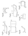
- the consisting of the clamp parts 3 and 4 clamp connects a heat source contained in the version 5 via a heat conducting device consisting of two metal strips 8 and 9, in Figs. 21 to 27 individually are shown, with the fluid line. 1
- the clamp parts 3 and 4 are at one end 10th or 11, right in Fig. 3, hinged together, the end 10 ( Figures 3 and 8) of the Clamping part 4 in a recess 12 (FIGS. 3 and 17) of the beak-shaped or fork-shaped end 11 engaged with play, so that the end 10 in the recess 12 is pivotable.
- clamp parts 3 and 4 each beak or fork-shaped, so they with their thighs 17 respectively 18 in each one of the recesses 19 and 20 between the legs 17 and 21 or 18 and 22 of the Ends 15 and 16 can intervene.
- the ends 15 and 16 of the clamp parts 3 and 4 are on the radially outer side of the leg 17 and the radial inner side of the leg 22 each with a Gearing 23 (FIGS. 3 and 18) and 24 (FIG. 8), which can be brought in accordance with FIG. 3 in engagement are when the leg 17 at the end 15 of the clamp member 3 in the recess 20 between the legs 17 and 21st and the end 10 of the clamp part 4 in the recess 12 at the end 11 of the clamp part 3 are introduced.
- the ends 15 and 16 of the clamp parts 3 and 4 form therefore one corresponding to the number of teeth of the gears 23 and 24 stepwise tensionable snap lock the clamp.
- the metal strip 8 of the heat conduction stands with a planar end 25 ( Figures 2, 21 to 24) with at least a heating element in the form of a PTC resistor 26 in the version 5 in heat and electrically conductive contact. With its other end 27, that according to the Curvature of the clamp part 4 is curved, is the metal strip 8 connected to the clamp part 4.
- the body part 2, the clamp part 3 and the socket 7 are essentially thermoplastic Plastic, wherein the metal strip 8 with his End 27 in the plastic of the clamp part 4, with his middle section in the plastic of the connecting part 6 and with its end 25 in the plastic version 7 is embedded and at the same time producing the Clamping part 4, the connecting part 6 and the socket 5 made of the same plastic, by injection molding, until bent to a radially outward at the end 27, lateral edge 28 and in the bottom of the socket 5 after above exposed contact surfaces 29 ( Figures 2 and 10) has been overmoulded with this plastic. Also the Metal strip 9 (Fig. 3, 25-27) is corresponding to the Curvature of the clamp part 3 arched and except for one lateral, radially outwardly angled edge 30 with molded thermoplastic.
- the female connector 7 ( Figures 1-5, 11-15) is for insertion a connector that has a power supply line (a cable) with the battery of the motor vehicle connected is.
- the socket 7 is also in Substantially made of thermoplastic material, in the Tongues 31 and 32 or pins, partially non-binding, are poured.
- These contact tongues 31, 32 (Fig. 13) are on the one hand with contacts 33, 34, the on the inside of a cover part 35 of the socket 7, leaving contact surfaces for electrical Contacting the or each PTC resistor 26, are cast in, and on the other hand with the metal strip 8 in connection.
- the lid member 35 becomes on the opening edge version 5, for example in the ultra or Mirror welding process, welded, so that the socket 5 is sealed and the contacts 33, 34th via contact spring elements 36, 37 (FIG. 14) with or each PTC resistor 26 are electrically connected.
- the heater shown has opposite to in an interruption of the fluid line 1 to be coupled Heating device has the advantage that it can be connected to any the risk of hypothermia or the Freezing of the flowing through the fluid line 1
- Fluid exposed point of the fluid line 1 means the clamp (3, 4) can be attached without this clamp from the outset before the production of Motor vehicle needs to be known and without the Fluid line 1 separated at this point or should be interrupted.
- the Mounting the heater on the fluid line extremely simple.
Landscapes
- Engineering & Computer Science (AREA)
- General Engineering & Computer Science (AREA)
- Mechanical Engineering (AREA)
- Chemical & Material Sciences (AREA)
- Combustion & Propulsion (AREA)
- Resistance Heating (AREA)
- Air-Conditioning For Vehicles (AREA)
- Pipe Accessories (AREA)
Abstract
Description
- Fig. 1
- eine Seitenansicht des Ausführungsbeispiels der erfindungsgemäßen Heizvorrichtung,
- Fig. 2
- den Querschnitt II-II der Fig. 1,
- Fig. 3
- den Querschnitt III-III der Fig. 1,
- Fig. 4
- eine Draufsicht auf die Heizvorrichtung nach Fig. 1,
- Fig. 5
- eine perspektivische Darstellung der Heizvorrichtung nach Fig. 1,
- Fig. 6
- eine Seitenansicht eines Teils der Heizvorrichtung nach Fig. 1 ohne die normalerweise fest damit verbundene Steckbuchse, die zur Einführung eines mit einer Stromversorgungsleitung verbundenen Steckers dient,
- Fig. 7
- eine Draufsicht auf den in Fig. 6 dargestellten Teil der Heizvorrichtung,
- Fig. 8
- den Schnitt VIII-VIII der Fig. 7,
- Fig. 9
- den Schnitt IX-IX der Fig. 7,
- Fig. 10
- eine perspektivische Ansicht des in Fig. 6 dargestellten Teils der Heizvorrichtung,
- Fig. 11
- eine Draufsicht auf die normalerweise mit dem in den Fig. 6 - 9 dargestellten Teil verbundene Steckbuchse,
- Fig. 12
- den Schnitt XII-XII der Fig. 11,
- Fig. 13
- die Ansicht der Steckbuchse von rechts in Fig. 11,
- Fig. 14
- eine Unteransicht der Steckbuchse,
- Fig. 15
- eine Seitenansicht der Steckbuchse,
- Fig. 16
- eine Seitenansicht eines Schellenteils der Heizvorrichtung nach Fig. 1,
- Fig. 17
- den Schnitt XVII-XVII der Fig. 16,
- Fig. 18
- eine Vorderansicht des Schellenteils nach Fig. 16,
- Fig. 19
- den Schnitt XIX-XIX der Fig. 18,
- Fig. 20
- eine perspektivische Ansicht des in den Fig. 16 - 18 dargestellten Schellenteils,
- Fig. 21
- einen Metallstreifen einer Wärmeleiteinrichtung, die in dem in Fig. 6 dargestellten Teil der Heizvorrichtung eingebettet ist und zur Übertragung der Wärme von einer Wärmequelle auf eine Fluidleitung dient,
- Fig. 22
- eine Ansicht des Metallstreifens von links in Fig. 21,
- Fig. 23
- eine Draufsicht auf den Metallstreifen nach Fig. 21,
- Fig. 24
- eine perspektivische Ansicht des Metallstreifens nach Fig. 21,
- Fig. 25
- eine Seitenansicht eines weiteren Metallstreifens, der in dem in den Fig. 16 -20 dargestellten Schellenteil eingebettet ist,
- Fig. 26
- eine Ansicht des weiteren Metallstreifens von links in Fig. 25 gesehen und
- Fig. 27
- eine perspektivische Ansicht des Metallstreifens nach Fig. 25.
Claims (16)
- Heizvorrichtung mit einer elektrischen Wärmequelle (26) zum Erwärmen eines Fluids in einer Fluidleitung (1) eines Kraftfahrzeugs, und mit einer Wärmeleiteinrichtung (8, 9), die mit der Wärmequelle (26) in Verbindung steht, dadurch gekennzeichnet, daß die Wärmeleiteinrichtung (8, 9) mit einer Schelle (3, 4) zum Verbinden der Wärmeleiteinrichtung (8, 9) mit der Fluidleitung (1) verbunden ist.
- Heizvorrichtung nach Anspruch 1, dadurch gekennzeichnet, daß die Wärmeleiteinrichtung (8, 9) einen Metallstreifen (8) aufweist, dessen eines Ende (25) mit der Wärmequelle (26) in Kontakt steht und dessen anderes Ende (27) mit der Schelle (3, 4) verbunden ist.
- Heizvorrichtung nach Anspruch 2, dadurch gekennzeichnet, daß die Schelle zwei Teile (3, 4) aufweist, die an ihrem einen Ende (10, 11) gelenkig zusammensteckbar und an ihrem anderen Ende (15, 16) durch einen Verschluß verbindbar sind.
- Heizvorrichtung nach Anspruch 3, dadurch gekennzeichnet, daß der Verschluß spannbar ist.
- Heizvorrichtung nach Anspruch 3 oder 4, dadurch gekennzeichnet, daß der Verschluß ein Rastverschluß ist.
- Heizvorrichtung nach einem der Ansprüche 3 bis 5, dadurch gekennzeichnet, daß der Verschluß an den zu verbindenden Enden (15, 16) der Schellenteile (3, 4) je eine von zwei in Eingriff bringbaren Verzahnungen (23, 24) aufweist.
- Heizvorrichtung nach Anspruch 6, dadurch gekennzeichnet, daß die eine Verzahnung (23) in einer Ausnehmung (19) in dem einen (16) der durch den Verschluß zu verbindenden Enden (15, 16) in die Ausnehmung (19) einführbar ist.
- Heizvorrichtung nach einem der Ansprüche 2 bis 7, dadurch gekennzeichnet, daß der Metallstreifen (8) eine Wölbung aufweist.
- Heizvorrichtung nach Anspruch 8, dadurch gekennzeichnet, daß die Wölbung zumindest in einem mit dem einen Schellenteil (4) verbundenen Endabschnitt (27) des Metallstreifens (8) eine zur Mittelachse der Fluidleitung (1) konzentrischen Krümmungsachse aufweist.
- Heizvorrichtung nach einem der Ansprüche 3 bis 9, dadurch gekennzeichnet, daß die Schellenteile (3, 4) im Spritzgießverfahren ausgebildet sind.
- Heizvorrichtung nach Anspruch 10, dadurch gekennzeichnet, daß die Schelle thermoplastischen Kunststoff aufweist.
- Heizvorrichtung nach Anspruch 11, dadurch gekennzeichnet, daß der Metallstreifen (8) durch den thermoplastischen Kunststoff der Schelle umspritzt ist.
- Heizvorrichtung nach einem der Ansprüche 11 oder 12, dadurch gekennzeichnet, daß der den Metallstreifen (8) umgebende Kunststoff an dem von der Schelle abgekehrten Ende des Metallstreifens (8) als Fassung (5) zur Aufnahme der Wärmequelle (26) geformt ist und der Kunststoff in der Fassung (5) wenigstens eine Kontaktfläche (19) des Metallstreifens (8) zur thermischen und elektrischen Kontaktierung durch wenigstens ein Heizelement (26) der Wärmequelle freiläßt.
- Heizvorrichtung nach Anspruch 13, dadurch gekennzeichnet, daß die Fassung (5) durch einen mit der Fassung (5) verschweißten Deckelteil (35) einer zur Einführung eines an einer Stromversorgungsleitung angeschlossenen Steckers vorgesehenen Steckbuchse (7) aus thermoplastischem Kunststoff verschlossen ist, deren Kontakte (31, 32) einerseits mit dem Metallstreifen (8) und andererseits mit wenigstens einem Kontakt (34, 35) an der Innenseite des Dekkelteils (35) verbunden sind, wobei das oder jedes in der Fassung (5) angeordnete Heizelement (26) mit einer Kontaktfläche (29) des Metallstreifens (8) und einem Kontakt (33, 34) am Deckelteil (35) in Verbindung steht.
- Heizvorrichtung nach Anspruch 13 oder 14, dadurch gekennzeichnet, daß das oder jedes Heizelement ein PTC-Widerstand ist.
- Heizvorrichtung nach einem der Ansprüche 10 bis 15, dadurch gekennzeichnet, daß die Wärmeleiteinrichtung (8, 9) in dem thermoplastischen Kunststoff des anderen Schellenteils (3) einen weiteren Metallstreifen (9) aufweist, der mit dem einen Metallstreifen (8) im Bereich des Schellengelenks in gelenkigem Kontakt steht und sich in Richtung zum Verschluß erstreckt.
Applications Claiming Priority (2)
| Application Number | Priority Date | Filing Date | Title |
|---|---|---|---|
| DE10326894 | 2003-06-14 | ||
| DE10326894A DE10326894B3 (de) | 2003-06-14 | 2003-06-14 | Heizvorrichtung mit einer elektrischen Wärmequelle zum Erwärmen eines Fluids in einer Fluidleitung eines Kraftfahrzeugs |
Publications (3)
| Publication Number | Publication Date |
|---|---|
| EP1486266A2 true EP1486266A2 (de) | 2004-12-15 |
| EP1486266A3 EP1486266A3 (de) | 2006-04-26 |
| EP1486266B1 EP1486266B1 (de) | 2011-04-06 |
Family
ID=32921170
Family Applications (1)
| Application Number | Title | Priority Date | Filing Date |
|---|---|---|---|
| EP04010741A Expired - Lifetime EP1486266B1 (de) | 2003-06-14 | 2004-05-06 | Heizvorrichtung mit einer elektrischen Wärmequelle zum Erwärmen eines Fluids in einer Fluidleitung eines Kraftfahrzeugs |
Country Status (7)
| Country | Link |
|---|---|
| US (1) | US6881933B2 (de) |
| EP (1) | EP1486266B1 (de) |
| JP (1) | JP3928629B2 (de) |
| CN (1) | CN1324232C (de) |
| CA (1) | CA2470273C (de) |
| DE (2) | DE10326894B3 (de) |
| MX (1) | MXPA04005078A (de) |
Cited By (1)
| Publication number | Priority date | Publication date | Assignee | Title |
|---|---|---|---|---|
| CN101799116A (zh) * | 2010-03-16 | 2010-08-11 | 河北亚大汽车塑料制品有限公司 | 用于输送液体的防冻管路 |
Families Citing this family (16)
| Publication number | Priority date | Publication date | Assignee | Title |
|---|---|---|---|---|
| DE202005012793U1 (de) * | 2005-08-11 | 2006-12-28 | Mann + Hummel Gmbh | Heizeinrichtung für Fluide |
| ES2682301T3 (es) | 2007-04-26 | 2018-09-19 | Voss Automotive Gmbh | Conector de tubería para tuberías de fluidos |
| DE202007015036U1 (de) | 2007-10-26 | 2009-03-12 | Voss Automotive Gmbh | Leitungsverbinder sowie Leitungssatz für fluidische Medien |
| DE202007018089U1 (de) | 2007-12-21 | 2009-05-07 | Voss Automotive Gmbh | Beheizbare Medienleitung |
| EP2222995B1 (de) | 2007-12-21 | 2014-12-10 | Voss Automotive GmbH | Leitungsverbinder für medienleitungen sowie konfektionierte medienleitung mit mindestens einem solchen leitungsverbinder |
| SE533533C2 (sv) * | 2009-08-04 | 2010-10-19 | Calix Ab | Elektrisk uppvärmningsanordning för fordon |
| TWM375766U (en) * | 2009-10-07 | 2010-03-11 | Top 1 Green Dev Co Ltd | Fuel combustion device for vehicle |
| TWM375767U (en) * | 2009-10-07 | 2010-03-11 | Top 1 Green Dev Co Ltd | Gasoline pipe and fuel combustion device of vehicle equipped with such a gasoline pipe |
| DE102010051550A1 (de) * | 2010-11-18 | 2012-05-24 | Voss Automotive Gmbh | Konfektionierte elektrisch beheizbare Medienleitung sowie Verfahren zum Herstellen einer solchen Medienleitung |
| DE102012014746A1 (de) | 2012-07-26 | 2014-02-13 | Mann + Hummel Gmbh | Heizvorrichtung für eine Fluidleitung |
| CN103344034B (zh) * | 2013-07-18 | 2015-12-09 | 东风汽车公司 | 一种用于汽车空调系统的高压ptc液体加热器 |
| JP6285829B2 (ja) * | 2014-09-10 | 2018-02-28 | 株式会社ニフコ | 流体用の配管装置 |
| FR3040950B1 (fr) * | 2015-09-16 | 2017-09-08 | Valeo Systemes Dessuyage | Adaptateur de conduite de liquide et dispositif de distribution de liquide de balais d'essuie-glace de vehicule automobile |
| US10396500B2 (en) | 2016-08-31 | 2019-08-27 | Norma U.S. Holding Llc | Electrically conductive conduit assembly |
| CN107131382A (zh) * | 2017-06-19 | 2017-09-05 | 孙时泽 | 一种水管连接端头 |
| KR20230041614A (ko) * | 2021-09-17 | 2023-03-24 | 에이에스엠 아이피 홀딩 비.브이. | 액체를 가열하기 위한 방법 및 장치 |
Citations (1)
| Publication number | Priority date | Publication date | Assignee | Title |
|---|---|---|---|---|
| EP1158158A1 (de) | 2000-05-25 | 2001-11-28 | David + Baader DBK GmbH | PTC-Heizeinrichtung |
Family Cites Families (9)
| Publication number | Priority date | Publication date | Assignee | Title |
|---|---|---|---|---|
| DE331645C (de) * | 1921-01-12 | Josef Vogel | Brennstoffvorwaermer | |
| US3475597A (en) * | 1968-03-18 | 1969-10-28 | Watlow Electric Mfg Co | Retainer or clamp for a cylindrical type heater |
| GB1308667A (en) * | 1970-11-20 | 1973-02-21 | Ass Elect Ind | Heating arrangements |
| IT1086606B (it) * | 1976-11-29 | 1985-05-28 | Althouse Victor E | Elemento di chiusura in gomma siliconica e procedimento per applicarlo |
| US4292503A (en) * | 1979-05-14 | 1981-09-29 | Emerson Electric Co. | Split-band electric heater |
| JPH04119597A (ja) * | 1990-09-07 | 1992-04-21 | Mitsubishi Electric Corp | 不揮発性半導体記憶装置のセンスアンプ |
| DE69124062T2 (de) * | 1990-11-02 | 1997-06-26 | Watlow Electric Mfg | Heizvorrichtung, speziell in Form eines Bandes oder Streifens |
| JP2877025B2 (ja) * | 1995-04-25 | 1999-03-31 | ヤマハ株式会社 | Frtp成形用材料と、これを用いて得られたfrtp管状成形体 |
| RU2204077C2 (ru) * | 1998-08-06 | 2003-05-10 | Карин Дауме Машинентайле Гмбх Унд Ко. Кг | Уплотнительное устройство для образования уплотнения на наружной поверхности, в частности, продолговатых, например, в основном, цилиндрических тел, например труб или кабелей |
-
2003
- 2003-06-14 DE DE10326894A patent/DE10326894B3/de not_active Expired - Fee Related
-
2004
- 2004-05-06 DE DE502004012367T patent/DE502004012367D1/de not_active Expired - Lifetime
- 2004-05-06 EP EP04010741A patent/EP1486266B1/de not_active Expired - Lifetime
- 2004-05-27 MX MXPA04005078A patent/MXPA04005078A/es unknown
- 2004-06-04 US US10/860,860 patent/US6881933B2/en not_active Expired - Fee Related
- 2004-06-08 CA CA002470273A patent/CA2470273C/en not_active Expired - Fee Related
- 2004-06-09 JP JP2004170911A patent/JP3928629B2/ja not_active Expired - Fee Related
- 2004-06-14 CN CNB2004100485808A patent/CN1324232C/zh not_active Expired - Fee Related
Patent Citations (1)
| Publication number | Priority date | Publication date | Assignee | Title |
|---|---|---|---|---|
| EP1158158A1 (de) | 2000-05-25 | 2001-11-28 | David + Baader DBK GmbH | PTC-Heizeinrichtung |
Cited By (2)
| Publication number | Priority date | Publication date | Assignee | Title |
|---|---|---|---|---|
| CN101799116A (zh) * | 2010-03-16 | 2010-08-11 | 河北亚大汽车塑料制品有限公司 | 用于输送液体的防冻管路 |
| CN101799116B (zh) * | 2010-03-16 | 2013-04-17 | 河北亚大汽车塑料制品有限公司 | 用于输送液体的防冻管路 |
Also Published As
| Publication number | Publication date |
|---|---|
| EP1486266B1 (de) | 2011-04-06 |
| CN1573076A (zh) | 2005-02-02 |
| DE502004012367D1 (de) | 2011-05-19 |
| CA2470273C (en) | 2008-02-05 |
| US20040251248A1 (en) | 2004-12-16 |
| US6881933B2 (en) | 2005-04-19 |
| JP2005002997A (ja) | 2005-01-06 |
| DE10326894B3 (de) | 2004-09-30 |
| CA2470273A1 (en) | 2004-12-14 |
| CN1324232C (zh) | 2007-07-04 |
| EP1486266A3 (de) | 2006-04-26 |
| JP3928629B2 (ja) | 2007-06-13 |
| MXPA04005078A (es) | 2005-07-01 |
Similar Documents
| Publication | Publication Date | Title |
|---|---|---|
| EP1486266B1 (de) | Heizvorrichtung mit einer elektrischen Wärmequelle zum Erwärmen eines Fluids in einer Fluidleitung eines Kraftfahrzeugs | |
| DE3117069C2 (de) | Rohrheizkörper und Verfahren zum Verbinden einer externen Anschlußleitung mit dem Kontaktstift des Heizelementes eines Rohrheizkörpers | |
| DE3904069A1 (de) | Wasserdichter stopfen fuer eine elektrische steckverbindung | |
| WO2008061572A2 (de) | Geschirmter steckverbinder und verfahren zu seiner herstellung | |
| DE202007018089U1 (de) | Beheizbare Medienleitung | |
| DE102004034038A1 (de) | Verbindung zwischen einem Kabelendstück und einem Kabelende | |
| DE3417811C1 (de) | Verfahren zum Anbringen eines Kupplungsteils am Ende einer elektrischen Leitung | |
| EP1610049B1 (de) | Schlauchverbindungssystem für einen beheizbaren Schlauch | |
| DE19809492C2 (de) | Elektrischer Verbinder | |
| DE102019205848A1 (de) | PTC-Heizelement und elektrische Heizvorrichtung mit einem solchen PTC-Heizelement und Verfahren zur Herstellung eines PTC-Heizelementes | |
| DE202007010602U1 (de) | Filterelement | |
| DE2942018C2 (de) | ||
| DE2658789A1 (de) | Steckverbindung | |
| DE4027952C3 (de) | Elektrische Verbindungseinrichtung | |
| DE1936039A1 (de) | Isolierter Drahtverbinder mit Einsteck-Kupplung | |
| DE3145816A1 (de) | Elektrischer stecker | |
| EP2318745B1 (de) | Anschlussvorrichtung für medienführende, elektrisch beheizbare schläuche | |
| DE3032718A1 (de) | Anschlussklemme fuer einen batteriepol | |
| DE7738717U1 (de) | Steckdose mit elektrischer Anschlußleitung | |
| EP0991151A2 (de) | Kontaktelement zur Verbindung einer Flachbandleitung mit Rundleitern und Drehverbinder mit einem derartigen Kontaktelement | |
| WO2020126881A1 (de) | Halterahmen für enen steckverbinder | |
| DE8028756U1 (de) | Kastenelement zur Aufnahme von elektrischen Kontaktbuchsenelementen | |
| DE202007018086U1 (de) | Leitungsverbinder für Medienleitungen sowie konfektionierte Medienleitung mit mindestens einem solchen Leitungsverbinder | |
| DE3739019A1 (de) | Pinzette fuer bipolare koagulation | |
| DE3037642A1 (de) | Vorrichtung fuer eine elektrische verbindung und gehaeuse zur aufnahme einer solchen vorrichtung |
Legal Events
| Date | Code | Title | Description |
|---|---|---|---|
| PUAI | Public reference made under article 153(3) epc to a published international application that has entered the european phase |
Free format text: ORIGINAL CODE: 0009012 |
|
| AK | Designated contracting states |
Kind code of ref document: A2 Designated state(s): AT BE BG CH CY CZ DE DK EE ES FI FR GB GR HU IE IT LI LU MC NL PL PT RO SE SI SK TR |
|
| AX | Request for extension of the european patent |
Extension state: AL HR LT LV MK |
|
| PUAL | Search report despatched |
Free format text: ORIGINAL CODE: 0009013 |
|
| AK | Designated contracting states |
Kind code of ref document: A3 Designated state(s): AT BE BG CH CY CZ DE DK EE ES FI FR GB GR HU IE IT LI LU MC NL PL PT RO SE SI SK TR |
|
| AX | Request for extension of the european patent |
Extension state: AL HR LT LV MK |
|
| 17P | Request for examination filed |
Effective date: 20060603 |
|
| AKX | Designation fees paid |
Designated state(s): DE FR SE |
|
| 17Q | First examination report despatched |
Effective date: 20070122 |
|
| RAP1 | Party data changed (applicant data changed or rights of an application transferred) |
Owner name: NORMA GERMANY GMBH |
|
| GRAP | Despatch of communication of intention to grant a patent |
Free format text: ORIGINAL CODE: EPIDOSNIGR1 |
|
| GRAS | Grant fee paid |
Free format text: ORIGINAL CODE: EPIDOSNIGR3 |
|
| GRAA | (expected) grant |
Free format text: ORIGINAL CODE: 0009210 |
|
| AK | Designated contracting states |
Kind code of ref document: B1 Designated state(s): DE FR SE |
|
| REF | Corresponds to: |
Ref document number: 502004012367 Country of ref document: DE Date of ref document: 20110519 Kind code of ref document: P |
|
| REG | Reference to a national code |
Ref country code: DE Ref legal event code: R096 Ref document number: 502004012367 Country of ref document: DE Effective date: 20110519 |
|
| REG | Reference to a national code |
Ref country code: SE Ref legal event code: TRGR |
|
| PLBE | No opposition filed within time limit |
Free format text: ORIGINAL CODE: 0009261 |
|
| STAA | Information on the status of an ep patent application or granted ep patent |
Free format text: STATUS: NO OPPOSITION FILED WITHIN TIME LIMIT |
|
| 26N | No opposition filed |
Effective date: 20120110 |
|
| REG | Reference to a national code |
Ref country code: DE Ref legal event code: R097 Ref document number: 502004012367 Country of ref document: DE Effective date: 20120110 |
|
| REG | Reference to a national code |
Ref country code: FR Ref legal event code: PLFP Year of fee payment: 12 |
|
| REG | Reference to a national code |
Ref country code: DE Ref legal event code: R082 Ref document number: 502004012367 Country of ref document: DE Representative=s name: PATENTANWAELTE OLBRICHT, BUCHHOLD, KEULERTZ PA, DE |
|
| REG | Reference to a national code |
Ref country code: FR Ref legal event code: PLFP Year of fee payment: 13 |
|
| PGFP | Annual fee paid to national office [announced via postgrant information from national office to epo] |
Ref country code: DE Payment date: 20160520 Year of fee payment: 13 |
|
| PGFP | Annual fee paid to national office [announced via postgrant information from national office to epo] |
Ref country code: FR Payment date: 20160520 Year of fee payment: 13 Ref country code: SE Payment date: 20160519 Year of fee payment: 13 |
|
| REG | Reference to a national code |
Ref country code: DE Ref legal event code: R119 Ref document number: 502004012367 Country of ref document: DE |
|
| REG | Reference to a national code |
Ref country code: SE Ref legal event code: EUG |
|
| PG25 | Lapsed in a contracting state [announced via postgrant information from national office to epo] |
Ref country code: SE Free format text: LAPSE BECAUSE OF NON-PAYMENT OF DUE FEES Effective date: 20170507 |
|
| REG | Reference to a national code |
Ref country code: FR Ref legal event code: ST Effective date: 20180131 |
|
| PG25 | Lapsed in a contracting state [announced via postgrant information from national office to epo] |
Ref country code: DE Free format text: LAPSE BECAUSE OF NON-PAYMENT OF DUE FEES Effective date: 20171201 |
|
| PG25 | Lapsed in a contracting state [announced via postgrant information from national office to epo] |
Ref country code: FR Free format text: LAPSE BECAUSE OF NON-PAYMENT OF DUE FEES Effective date: 20170531 |