EP1484918B1 - Bildwiedergabeeinrichtung, bildhalteeinrichtung und bildwiedergabesystem - Google Patents
Bildwiedergabeeinrichtung, bildhalteeinrichtung und bildwiedergabesystem Download PDFInfo
- Publication number
- EP1484918B1 EP1484918B1 EP03766636A EP03766636A EP1484918B1 EP 1484918 B1 EP1484918 B1 EP 1484918B1 EP 03766636 A EP03766636 A EP 03766636A EP 03766636 A EP03766636 A EP 03766636A EP 1484918 B1 EP1484918 B1 EP 1484918B1
- Authority
- EP
- European Patent Office
- Prior art keywords
- setting
- image
- reproduction
- data
- reproducing device
- Prior art date
- Legal status (The legal status is an assumption and is not a legal conclusion. Google has not performed a legal analysis and makes no representation as to the accuracy of the status listed.)
- Expired - Lifetime
Links
- 238000000034 method Methods 0.000 claims description 53
- 230000001419 dependent effect Effects 0.000 claims description 46
- 238000006243 chemical reaction Methods 0.000 claims description 38
- 230000006870 function Effects 0.000 claims description 26
- 230000004044 response Effects 0.000 claims description 8
- 238000013461 design Methods 0.000 abstract description 6
- 238000004891 communication Methods 0.000 description 20
- 238000012937 correction Methods 0.000 description 16
- 238000010586 diagram Methods 0.000 description 14
- 230000005540 biological transmission Effects 0.000 description 9
- 239000004973 liquid crystal related substance Substances 0.000 description 8
- 238000003825 pressing Methods 0.000 description 7
- 238000003384 imaging method Methods 0.000 description 6
- 238000003490 calendering Methods 0.000 description 3
- 238000011161 development Methods 0.000 description 2
- 230000006835 compression Effects 0.000 description 1
- 238000007906 compression Methods 0.000 description 1
- 238000012790 confirmation Methods 0.000 description 1
- 230000007423 decrease Effects 0.000 description 1
- 238000009877 rendering Methods 0.000 description 1
- 230000002747 voluntary effect Effects 0.000 description 1
Images


Classifications
-
- H—ELECTRICITY
- H04—ELECTRIC COMMUNICATION TECHNIQUE
- H04N—PICTORIAL COMMUNICATION, e.g. TELEVISION
- H04N1/00—Scanning, transmission or reproduction of documents or the like, e.g. facsimile transmission; Details thereof
- H04N1/00127—Connection or combination of a still picture apparatus with another apparatus, e.g. for storage, processing or transmission of still picture signals or of information associated with a still picture
- H04N1/00278—Connection or combination of a still picture apparatus with another apparatus, e.g. for storage, processing or transmission of still picture signals or of information associated with a still picture with a printing apparatus, e.g. a laser beam printer
-
- G—PHYSICS
- G06—COMPUTING; CALCULATING OR COUNTING
- G06F—ELECTRIC DIGITAL DATA PROCESSING
- G06F3/00—Input arrangements for transferring data to be processed into a form capable of being handled by the computer; Output arrangements for transferring data from processing unit to output unit, e.g. interface arrangements
- G06F3/12—Digital output to print unit, e.g. line printer, chain printer
- G06F3/1201—Dedicated interfaces to print systems
- G06F3/1202—Dedicated interfaces to print systems specifically adapted to achieve a particular effect
- G06F3/1203—Improving or facilitating administration, e.g. print management
- G06F3/1204—Improving or facilitating administration, e.g. print management resulting in reduced user or operator actions, e.g. presetting, automatic actions, using hardware token storing data
-
- G—PHYSICS
- G06—COMPUTING; CALCULATING OR COUNTING
- G06F—ELECTRIC DIGITAL DATA PROCESSING
- G06F3/00—Input arrangements for transferring data to be processed into a form capable of being handled by the computer; Output arrangements for transferring data from processing unit to output unit, e.g. interface arrangements
- G06F3/12—Digital output to print unit, e.g. line printer, chain printer
- G06F3/1201—Dedicated interfaces to print systems
- G06F3/1223—Dedicated interfaces to print systems specifically adapted to use a particular technique
- G06F3/1237—Print job management
- G06F3/1253—Configuration of print job parameters, e.g. using UI at the client
- G06F3/1254—Automatic configuration, e.g. by driver
-
- G—PHYSICS
- G06—COMPUTING; CALCULATING OR COUNTING
- G06F—ELECTRIC DIGITAL DATA PROCESSING
- G06F3/00—Input arrangements for transferring data to be processed into a form capable of being handled by the computer; Output arrangements for transferring data from processing unit to output unit, e.g. interface arrangements
- G06F3/12—Digital output to print unit, e.g. line printer, chain printer
- G06F3/1201—Dedicated interfaces to print systems
- G06F3/1278—Dedicated interfaces to print systems specifically adapted to adopt a particular infrastructure
- G06F3/128—Direct printing, e.g. sending document file, using memory stick, printing from a camera
-
- H—ELECTRICITY
- H04—ELECTRIC COMMUNICATION TECHNIQUE
- H04N—PICTORIAL COMMUNICATION, e.g. TELEVISION
- H04N2201/00—Indexing scheme relating to scanning, transmission or reproduction of documents or the like, and to details thereof
- H04N2201/0008—Connection or combination of a still picture apparatus with another apparatus
- H04N2201/0013—Arrangements for the control of the connected apparatus by the still picture apparatus
-
- H—ELECTRICITY
- H04—ELECTRIC COMMUNICATION TECHNIQUE
- H04N—PICTORIAL COMMUNICATION, e.g. TELEVISION
- H04N2201/00—Indexing scheme relating to scanning, transmission or reproduction of documents or the like, and to details thereof
- H04N2201/0008—Connection or combination of a still picture apparatus with another apparatus
- H04N2201/0015—Control of image communication with the connected apparatus, e.g. signalling capability
-
- H—ELECTRICITY
- H04—ELECTRIC COMMUNICATION TECHNIQUE
- H04N—PICTORIAL COMMUNICATION, e.g. TELEVISION
- H04N2201/00—Indexing scheme relating to scanning, transmission or reproduction of documents or the like, and to details thereof
- H04N2201/0077—Types of the still picture apparatus
- H04N2201/0084—Digital still camera
-
- H—ELECTRICITY
- H04—ELECTRIC COMMUNICATION TECHNIQUE
- H04N—PICTORIAL COMMUNICATION, e.g. TELEVISION
- H04N2201/00—Indexing scheme relating to scanning, transmission or reproduction of documents or the like, and to details thereof
- H04N2201/32—Circuits or arrangements for control or supervision between transmitter and receiver or between image input and image output device, e.g. between a still-image camera and its memory or between a still-image camera and a printer device
- H04N2201/3201—Display, printing, storage or transmission of additional information, e.g. ID code, date and time or title
- H04N2201/3225—Display, printing, storage or transmission of additional information, e.g. ID code, date and time or title of data relating to an image, a page or a document
- H04N2201/3242—Display, printing, storage or transmission of additional information, e.g. ID code, date and time or title of data relating to an image, a page or a document of processing required or performed, e.g. for reproduction or before recording
Definitions
- the present invention relates to an image reproducing device, an image holding device, and an image reproducing system, and particularly relates to an image reproducing device, an image holding device, and an image reproducing system capable of reproducing image data transmitted from the image holding device to the image reproducing device based on reproduction setting in the image reproducing device.
- the digital camera is a device which is connected to a printer for printing. Namely, it is possible to directly connect the digital camera to the printer by a USB (Universal Serial Bus) communication interface cable or the like and print an image taken by the digital camera with the printer. In this case, not only image data but also print setting when printing based on the image data is performed is transmitted from the digital camera to the printer.
- USB Universal Serial Bus
- the printer is provided with a control panel or the like in its printer main body, and print setting for a print operation to be executed hereafter can be performed by a user's operation of the control panel or the like.
- the case is assumed where the user wants to perform print setting on the side of the printer in which the user is used to operating and where the user does not want to perform print setting on the side of the digital camera in which the user is not used to operating.
- the user wants to perform print setting on the side of the printer in which the user is used to operating and where the user does not want to perform print setting on the side of the digital camera in which the user is not used to operating.
- user-friendliness increases.
- the aforementioned problem is not limited to between the digital camera and the printer.
- an image holding device a computer which holds image data on a hard disk and the like are given in addition to the digital camera
- an image reproducing device a projector which projects an image based on the image data and the like are given in addition to the printer. In such an image reproducing system, it is desired to improve the user-friendliness of reproduction setting when the image data is reproduced.
- the present invention is made in view of the aforementioned problem, and an object of the present invention is to reduce the burden of development imposed on manufactures of image holding devices such as a digital camera and improve user-friendliness by making it possible to reproduce an image data transmitted from the image holding device to an image reproducing device based on reproduction setting of the image reproducing device.
- an image reproducing device which is connectable to an image holding device via a USB interface, wherein the image reproducing device functions as a USB host and the image holding device functions as a USB device, and the image reproducing device obtains image data of digital image and reproduction setting data from the image holding device, a setting for a reproduction of the image data being designated in the reproduction setting data
- the image reproducing device comprises: a judgment section which judges whether the reproduction setting data is dependent setting which designates reproduction based on reproducing device setting set in the image reproducing device or independent setting which designates reproduction based on individual setting designated in the reproduction setting data; and a reproduction executor which reproduces the image data based on the reproducing device setting set in the image reproducing device when the judgment section judges that the reproduction setting data is the dependent setting and reproduces the image data based on the individual setting designated in the reproduction setting data when the judgment section judges that the reproduction setting data is the independent setting, characterised in that said image reproducing device further comprises: a judgment section which judges whether the reproduction setting data is dependent setting which designates reproduction based on reproduc
- an image holding device which is connectable to an image reproducing device via a USB interface
- the image reproducing device includes a USB host controlling
- the image holding device comprises: an image data holder which holds image data of digital image; an operation unit which is to set a reproduction setting data in which a setting for reproduction of the image data is designated and which is to instruct the image holding device to reproduce the image data; a request command generator which generates a request command which requests to reproduce the image data in response to the operation unit, characterised in that , said image holding device further comprises: a USB device controller which allows the image reproducing device to access the image data in the image data holder under a control of the image reproducing device, wherein the USB device controller periodically receives an Interrupt In command from the image reproducing device, and the request command is transmitted to the image reproducing device if the request command has been generated when the Interrupt In command is received, and wherein the reproduction setting data containing dependent setting or independent setting is transmitted from the image holding device to the image reproducing device,
- a control method of an image reproducing device comprises the steps of: receiving image data of digital image; receiving reproduction setting data, a setting for a reproduction of the image data being designated in the reproduction setting data; judging whether the reproduction setting data is dependent setting which designates reproduction based on reproducing device setting set in the image reproducing device or independent setting which designates reproduction based on individual setting designated in the reproduction setting data; reproducing the image data based on the reproducing device setting set in the image reproducing device when it is judged that the reproduction setting data is the dependent setting; and reproducing the image data based on the individual setting designated in the reproduction setting data when it is judged that the reproduction setting data is the independent setting, characterised in that , said control method further comprises the steps of: periodically transmitting an Interrupt In command to the image holding device; receiving from the image holding device, a request command which comprises a request to reproduce the image data based on the reproduction setting data if the request command has been generated when the image holding device receives the Interrupt In command; and controlling the image holding device
- a control method of an image holding device comprises the steps of: holding image data of an digital image in the image data holder; setting a reproduction setting data in which a setting for reproduction of the image data is designated and which is to instruct the image holding device to reproduce the image data; generating a request command which requests to reproduce the image data, characterised in that , said control method further comprises the steps of: allowing the image reproducing device to access the image data in the image data holder under a control of the image reproducing device; the USB device controller periodically receiving an Interrupt In command from the image reproducing device; transmitting the request command to the image reproducing device if the request command has been generated when the Interrupt In command is received; and transmitting, to the image reproducing device, reproduction setting data containing setting when the image data is reproduced, the reproduction setting data containing dependent setting which designates reproduction of the image data based on reproducing device setting set in the image reproducing device or independent setting which designates reproduction of the image data based on individual setting designated in the reproduction setting data.
- a program which causes an image reproducing device to execute procedure comprising the steps of:receiving image data of digital image; receiving reproduction setting data, a setting for a reproduction of the image data being designated in the reproduction setting data; judging whether the reproduction setting data is dependent setting which designates reproduction based on reproducing device setting set in the image reproducing device or independent setting which designates reproduction based on individual setting designated in the reproduction setting data; reproducing the image data based on the reproducing device setting set in the image reproducing device when it is judged that the reproduction setting data is the dependent setting; and reproducing the image data based on the individual setting designated in the reproduction setting data when it is judged that the reproduction setting data is the independent setting, characterised in that , said procedure further comprises the steps of: periodically transmitting an Interrupt In command to the image holding device; receiving from the image holding device, a request command which comprises a request to reproduce the image data based on the reproduction setting data if the request command has been generated when the image holding device receives the Interrupt In command; and
- a program causes an image holding device to execute procedure comprising the steps of: holding image data of a digital image in an image data holder; setting a reproduction setting data in which a setting for reproduction of the image data is designated and which is to instruct the image holding device to reproduce the image data; generating a request command which requests to reproduce the image data; characterised in that , said procedure further comprises the step of: allowing the image reproducing device to access the image data in the image data holder under a control of the image reproducing device; the USB device controller periodically receiving an Interrupt In command from the image reproducing device; transmitting the request command to the image reproducing device if the request command has been generated when the Interrupt In command is received; transmitting the image data held in the image data holder to an image reproducing device; and transmitting, to the image reproducing device, reproduction setting data containing setting when the image data is reproduced, the reproduction setting data containing dependent setting which designates reproduction of the image data based on reproducing device setting set in the image reproducing device or independent setting
- a record medium in which a program is recorded wherein the program causes an image reproducing device, which is connectable to an image holding device via a USB interface, wherein the image reproducing device functions as a USB host and the image holding device functions as a USB device, to execute procedure comprising the steps of: receiving image data of digital image; receiving reproduction setting data, a setting for a reproduction of the image data being designated in the reproduction setting data; judging whether the reproduction setting data is dependent setting which designates reproduction based on reproducing device setting set in the image reproducing device or independent setting which designates reproduction based on individual setting designated in the reproduction setting data, reproducing the image data based on the reproducing device setting set in the image reproducing device when it is judged that the reproduction setting data is the dependent setting; and reproducing the image data based on the individual setting designated in the reproduction setting data when it is judged that the reproduction setting data is the independent setting, characterised in that , said procedure further comprises the steps of: periodically transmitting an Interrupt In command to the image holding device;
- a record medium in which a program is recorded wherein the program causes an image holding device, which is connectable to an image reproducing device via a USB interface
- the image reproducing device includes a USB host controller, to execute procedure comprising the steps of: holding image data in an image data holder; setting a reproduction setting data in which a setting for reproduction of the image data is designated and which is to instruct the image holding device to reproduce the image data; generating a request command which requests to reproduce the image data; characterised in that , said procedure further comprises the steps of: allowing the image reproducing device to access the image data in the image data holder under a control of the image reproducing device, the USB device controller periodically receiving an Interrupt In command from the image reproducing device; transmitting the request command to the image reproducing device if the request command has been generated when the Interrupt In command is received; transmitting the image data held in the image data holder to an image reproducing device; and transmitting, to the image reproducing device, reproduction setting data containing setting when the
- an image reproducing system including an image holding device and an image reproducing device connected to the image holding device, wherein the image reproducing device is connectable to the image holding device via a USB interface, wherein the image reproducing device functions as a USB host and the image holding device functions as a USB device,
- the image holding device comprises: an image data holder which holds image data of digital image; an operation unit which is to set a reproduction setting data in which a setting for reproduction of the image data is designated and which is to instruct the image holding device to reproduce the image data; a request command generator which generates a request command which requests to reproduce the image data in response to the operation unit, characterised in that , said image holding device further comprises: a USB device controller which allows the image reproducing device to access the image data in the image data holder under a control of the image reproducing device, wherein the USB device controller periodically receives an Interrupt In command from the image reproducing device, and the request command is transmitted to the image reproducing device if the request command has been generated when the Interrupt
- An embodiment of the present invention is designed in such a manner that an option of "Depend on printer setting" is provided as an option of print setting for the paper type, paper size, and so on, and when such an option is selected as print setting, at the time of printing, a printer executes a print operation based on the contents of print setting set on the printer side. Further details will be given below.
- Fig. 1 is a block diagram explaining the entire configuration of a print system according to this embodiment.
- the print system according to this embodiment includes a digital camera 10 and a printer 20 connected to the digital camera 10 via a USB communication interface cable 30.
- the digital camera 10 includes a memory 11, an imaging unit 13, a camera controller 15, and a device controller 17.
- Image data taken by the imaging unit 13 is stored in the memory 11. This image data is stored, for example, in the form of a JPEG file or some other general format file.
- the imaging unit 13 takes a picture and converts it into an electrical signal.
- the camera controller 15 controls operations of respective portions of the digital camera 10.
- the device controller 17 controls communication with a USB host such as the printer 20.
- the camera controller 15 includes various kinds of operation buttons including a shutter button, a liquid crystal display panel, and so on. Based on a shutter button operation, the camera controller 15 drives the imaging unit 13 and allows the imaging unit 13 to take a picture, receives an electrical signal of a taken image from the imaging unit 13, creates a file of image data, and writes the file into the memory 11, or based on a predetermined image reference button operation, reads a desired image from the memory 11 and displays the image on the liquid crystal display panel.
- buttons including a shutter button, a liquid crystal display panel, and so on.
- the camera controller 15 creates a control command (printer status request) which requests acquisition of a printer status regularly, selects and reads a file of image data to be printed from the memory 11 based on a user's image selection button operation, generates print setting data indicating the contents of print setting (for example, the number of copies to be printed, paper type, paper size, layout, date print, print quality, automatic correction, and the like) based on a user's print setting button operation, creates a control command (print request) which requests print execution based on a user's print request button operation following the image selection button operation, or creates a control command (print stop request) which requests a print stop based on a user's print stop button operation.
- a control command printer status request
- the device controller 17 has a function of communicating with the USB host while meeting the USB standard as a USB storage class device. Hence, the USB host can search various directories in the memory 11 and freely access a desired data file.
- the device controller 17 can transmit the aforementioned control commands such as the printer status request, print request, and print stop request created by the camera controller 15 to the printer 20 in virtually the same manner that the digital camera 10 voluntarily transmits the control commands.
- the printer 20 includes a print controller 21, a print engine 23, a host controller 25, and a control panel 27.
- the print controller 21 performs the transmission of the printer status, reading of the image file to be printed from the memory 11, rendering of a print image, and other various controls in response to the printer status request, print request, print stop request, and so on transmitted from the digital camera 10.
- the host controller 25 has a function of communicating with the USB device as the USB host.
- the print engine 23 executes a print operation under the control of the print controller 21.
- the print controller 21 includes a function of receiving general-purpose compression format image data such as a JPEG file or some other general format file, expanding the image data, and converting it into bitmap image data, a color conversion function of converting an RGB pixel value of the bitmap image data into a CMYK pixel value, and a halftoning function of converting the multiple-tone pixel value of the color-converted bitmap image data into an area coverage modulation pixel value in which dots and blanks are represented.
- general-purpose compression format image data such as a JPEG file or some other general format file
- expanding the image data and converting it into bitmap image data
- a color conversion function of converting an RGB pixel value of the bitmap image data into a CMYK pixel value
- a halftoning function of converting the multiple-tone pixel value of the color-converted bitmap image data into an area coverage modulation pixel value in which dots and blanks are represented.
- the digital camera 10 need not necessarily include a function of expanding, color-converting, and halftoning the image data file to be printed such as a JPEG file stored in the memory 11, and it is only required to include a function of transmitting the image data file as it is to the printer 20. Consequently, the advantage that the configuration of the digital camera 10 need not be customized to each model of the printer 20 and may be for general purpose use can be obtained.
- the host controller 25 has a function of reading and writing a desired data file in a desired directory by accessing the memory 11 of the digital camera 10, which functions as a storage class USB device, in accordance with the USB standard. Although details will be described later, the host controller 25 can receive the aforementioned control commands such as the printer status request, print request, and print stop request created by the camera controller 15 from the digital camera 10 in virtually the same manner that the control commands are transmitted voluntarily from the digital camera 10.
- the control panel 27 is a panel operated when the user performs print setting and registers it with the printer 20. Namely, when the user performs print setting composed of setting items such as the number of copies to be printed, paper type, paper size, layout, date print, print quality, automatic correction, and so on and registers the print setting with the printer 20, the user performs necessary setting and registration by operating the control panel 27.
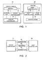
- Fig. 2 is a diagram showing logical pipes (logical communication channels) used when the device controller 17 of the digital camera 10 and the host controller 25 of the printer 20 communicate with each other.
- control pipe 41 is used for the transmission of various kinds of control commands from the digital camera 10 to the printer 20 and from the printer 20 to the digital camera 10.
- the bulk pipe 43 is used for data transmission including the transmission of the image data file from the digital camera 10 to the printer 20 and the transmission of the printer status data from the printer 20 to the digital camera 10.
- the interrupt pipe 45 is used for the transmission of a request inquiry command of "Interrupt In" from the printer 20 to the digital camera 10.
- USB standard prescribes nothing about the use of the interrupt pipe 45 in regard to communication by the storage device.
- interrupt pipe 45 by effectively using the interrupt pipe 45, various kinds of control commands can be transmitted practically voluntarily from the USB storage type digital camera 10 to the USB host printer 20.
- the printer 20 when the printer 20 is connected with the digital camera 10 via the USB communication interface cable 30, the printer 20 transmits the "Interrupt In” command to the digital camera 10 through the interrupt pipe 45 at very short intervals from the user's standpoint, for example, at least once per millisecond. Each time the digital camera 10 receives the Interrupt In" command, the digital camera 10 transmits a reply thereto to the printer 20 through the control pipe 41.
- control command such as the aforementioned printer status request, print request, or print stop request was created in the digital camera 10 at a point in time when the digital camera 10 has received the "Interrupt In” command
- the digital camera 10 transmits the control command as a reply to the "Interrupt In” command to the printer 20.
- the printer 20 interprets the transmitted control command and executes the operation (for example, the transmission of the printer status, execution of a print operation, or stop of the print operation) requested by the digital camera 10. As a result, it becomes possible to operate the printer 20 seemingly under the practically voluntary control of the digital camera 10.
- the printer 20 when executing a print operation in response to the print request, the printer 20 reads various data resources (for example, the image data file to be printed, the print setting data file, and so on) necessary for the print operation from the digital camera 10 at its own discretion by using the fact that the digital camera 10 is a storage class. Therefore, the digital camera 10 has only to perform the operation as the storage class of storing the data resources necessary for the print operation in the memory 11 and reading the data resource in response to a read request from the printer 20.
- various data resources for example, the image data file to be printed, the print setting data file, and so on
- Fig. 3 the flow of initial communication performed at the early stages after a communication connection by USB has been established between the printer 20 and the digital camera 10 will be explained based on Fig. 3 .
- Fig. 3 when the printer 20 and the digital camera 10 are connected by the USB communication interface cable 30 while both of them are already powered on, or when the printer 20 and the digital camera 10 are powered on while both of them are already connected by the USB communication interface cable 30, a USB communication connection is established between the printer 20 and the digital camera 10.
- the host controller 25 of the printer 20 acquires from the device controller 17 of the digital camera 10 a "device descriptor" in which the configuration thereof as the USB device is described (step S1).
- the device descriptor from the digital camera 10 contains an "interface descriptor” in which it is described that the digital camera 10 is a storage class device.
- the interface descriptor contains a "string descriptor” in which plural end points of the USB used by the digital camera 10 (end points where packets are transmitted or received by using any of three kinds of pipes 41, 43, and 45 shown in Fig. 2 ) are enumerated.
- this string descriptor in addition to end points which are to be possessed by a storage device defined by the USB standard (for example, a "Bulk Out” end point and a “Bulk In” end point), an "Interrupt In” end point which is an additional end point in this embodiment is described. Accordingly, the host controller 25 of the printer 20 confirms from the interface descriptor and the strings descriptor thereof that the digital camera 10 is a storage class device and a device which uses the "Interrupt In” command (command to inquire about a request on the USB device side).
- the printer 20 which has acquired the device descriptor of the digital camera 10 transmits a "print protocol confirmation command" to the digital camera 10 through the control pipe 41 within a predetermined short time (for example, within one second) from this point in time (step S4). Thereby, the printer 20 notifies the digital camera 10 of the type of a used communication protocol (namely, the type which uses the "Interrupt In” command), the protocol version, and the like.
- the printer 20 transmits the "Interrupt In” command to the digital camera 10 through the interrupt pipe 45 periodically, for example, once per millisecond (step S2, Step S5, and so on).
- the digital camera 10 determines whether some control command is generated within the digital camera 10 at that point in time. If no control command is generated, the digital camera 10 transmits a "Nak" message", which means no request, to the printer 20 through the control pipe 41 (step S3 and so on).
- the digital camera 10 transmits this control command to the printer 20 through the control pipe 41 (step S6 and so on).
- such a control command is the printer status request, the print request, the print stop request, or the like.
- the printer status request is transmitted to the printer 20 as a reply to the "Interrupt In" command in step S5.
- the printer 20 which has received the printer status request checks up on the latest printer status and writes data indicating the printer status into a predetermined directory in the memory 11 of the digital camera 10 through the bulk pipe 43 (step S7). Thereby, the digital camera 10 acquires the latest printer status. Hence, for example, this printer status can be displayed on the liquid crystal display panel or the like of the digital camera 10.
- the printer 20 when the printer 20 is brought into a state capable of accepting the print request after the communication connection has been established, at the first reception of the printer status request in the state (step S6), the printer 20 not only transmits the printer status data to the digital camera 10 (step S7) but also transmits a message to notify that the print request can be accepted to the digital camera 10 through the control pipe 41 (step S8).
- the timing in which the printer status request is generated in the digital camera 10 can be changed depending on the design of the digital camera 10, and the timing can be set at regular intervals, for example, at five-second intervals or at one-second intervals, for example, during the period from the transmission of the print request to the printer 20 till printing is completed, or during the period from the transmission of the print stop request to the printer 20 till printing is stopped.
- Fig. 4 shows an example of a communication procedure when the print request is transmitted from the digital camera 10 to the printer 20 and the printer 20 executes a print operation.
- the printer 20 transmits the "Interrupt In" command to the digital camera 10 at predetermined time intervals (step S11, step S13, step S17, step S21, and so on).
- step S13 when the print request is generated in the digital camera 10 at a point in time when the "Interrupt In" command has been received, the digital camera 10 transmits the print request as a reply to the "Interrupt In” command to the printer 20 through the control pipe 41 (step S14).
- the printer 20 which has received this print request transmits a command (resource file request command) to read resource files necessary for printing requested by the print request from the memory 11 of the digital camera 10 to the digital camera 10 (step S15).
- a command resource file request command
- the printer 20 reads the necessary resource files from the memory 11 of the digital camera 10 through the intermediation of the device controller 17 of the digital camera 10 (step S16), and executes a print operation based on the resource files.
- the resource files necessary for printing includes the image data file to be printed (its path name and file name are described in the print request), the print setting file of the print setting data in which setting is described in various setting items on printing (its path name and file name are described in the print request), and so on.
- the printer 20 reads these resource files from the memory 11 of the digital camera 10 at its own discretion and performs conversion processes such as expansion, color conversion, and halftoning, and hence the digital camera 10 need not perform any complicated process in particular.
- these image data file and print setting data file are stored in the memory 11 of the digital camera 10 and read from the memory 11 by the printer 20, and also in this case, the image data file and the print setting data file are transmitted from the digital camera 10 through the USB connection interface cable 30 and received by the printer 20.
- these image data file and print setting data file are transmitted from the digital camera 10 to the printer 20.
- the printer 20 transmits the "Interrupt In” command to the digital camera 10 at the predetermined time intervals (step S17 and so on).
- the digital camera 10 which has received the "Interrupt In” command after transmitting the print request (after step S14) transmits a printer status request to the printer 20 (step S18 and so on).
- the printer 20 which has received this printer status request during printing not only transmits the printer status to the digital camera 10 (step S19) but also checks up on the latest print state (for example, the number of as-yet-unprinted sheets or the number of printed sheets) and transmits a message that the printer is printing, containing data on the latest print state (step S20).
- the printer 20 transmits the "Interrupt In” command to the digital camera 10 at the predetermined time intervals (step S21).
- the printer 20 When the printer 20 has received the printer status request from the digital camera 10 after the completion of printing (step S22), the printer 20 not only transmits the printer status (step S23) but also transmits a message that printing has been completed to the digital camera 10 through the control pipe 41 (step S24).
- the digital camera 10 which has received the message that the printing has been completed controls the operation of the digital camera 10 itself so that a new print request can be issued.
- Fig. 5 is a diagram showing an example of the structure of a print setting data file PSET stored in the memory 11 of the digital camera 10
- Fig. 6 is a diagram showing a list of options of setting items prescribed in the print setting data file PSET.
- the print setting data file PSET includes a vendor ID T10, a number of copies to be printed T11, a paper type T12, a paper size T13, a layout T14, a date print T15, a print quality T16, and an automatic correction T17 as setting items.
- the vendor ID T10 information to specify the vendor of the printer is stored.
- the number of copies to be printed T11 information setting the number of copies of the image data to be printed, which is transmitted to the printer 20 together with the print setting data file PSET, (for example, two copies per image) is stored.
- the paper type T12 information specifying the type of print paper on which the image data is printed is stored. As shown in Fig. 6 , in this embodiment, three options of "Depend on printer setting", "plain paper”, and "calendered paper” are provided as options of the paper type T12.
- the printer 20 When “Depend on printer setting" is stored in the paper type T12, the printer 20 performs conversion processes such as expansion, color conversion, and halftoning on the image data based on the designation of the paper type set at this point in time in the printer 20 instead of the designation thereof from the digital camera 10 and executes a print operation.
- conversion processes such as expansion, color conversion, and halftoning on the image data based on the designation of the paper type set at this point in time in the printer 20 instead of the designation thereof from the digital camera 10 and executes a print operation.
- "plain paper” or “calendered paper” is stored in the paper type T12 and designated, priority is given to the designation from the digital camera 10.
- the paper size T13 information specifying the size of print paper on which the image file is printed is stored.
- six options of “Depend on printer setting”, “postcard”, “100 mm ⁇ 150 mm”, “A6", “A4", and “roll paper” are provided as options of the paper size T13.
- the printer 20 executes a print operation based on the designation of a paper size set at this point in time in the printer 20 instead of the designation thereof from the digital camera 10. Namely, the printer 20 performs conversion processes such as expansion, color conversion, and halftoning on the image data so as to fit the paper size set in the printer and executes the print operation.
- postcard "100 mm ⁇ 150 mm”, “A6", “A4", or "roll paper” is stored in the paper size T13, priority is given to the designation from the digital camera 10.
- the printer 20 performs conversion processes such as expansion, color conversion, and halftoning on the image data so as to fit the postcard size and executes a print operation.
- the printer 20 executes a print operation based on the designation of a layout set at this point in time in the printer 20 instead of the designation thereof from the digital camera 10. Namely, the printer 20 performs conversion processes such as expansion, color conversion, and halftoning on the image data so as to fit the layout set in the printer and executes the print operation.
- “1-screen print (bordered)” is stored in the layout T14, based on this designation, the printer 20 performs conversion processes such as expansion, color conversion, and halftoning on the image data in the layout in which one image is printed on one piece of print paper and so as to fit the bordered layout, and executes a print operation.
- “1-screen print (borderless)” is stored in the layout T14, based on this designation, the printer 20 performs conversion processes such as expansion, color conversion, and halftoning on the image data in the layout in which one image is printed on one piece of print paper and so as to fit the borderless layout, and executes a print operation.
- the printer 20 executes a print operation based on the designation of the presence/absence of date print which is set at this point in time in the printer 20 instead of the designation thereof from the digital camera 10. Namely, the printer 20 performs conversion processes such as expansion, color conversion, and halftoning on the image data so as to fit the setting of the presence/absence of date print registered with the printer and executes the print operation.
- the printer 20 When "Do not print date” is stored in the date print T15, based on this designation, the printer 20 performs conversion processes such as expansion, color conversion, and halftoning on the image so as not to print the picture taking date, and executes a print operation.
- conversion processes such as expansion, color conversion, and halftoning on the image data, for example, so as to print the picture taking date in the right corner of the image to be printed over the image, and executes a print operation.
- the print quality T16 information specifying the quality when the image file is printed is stored.
- four options of “Depend on printer setting”, “highest picture quality”, “high picture quality”, and “high-speed printing” are provided as options of the print quality T16.
- the printer 20 executes a print operation based on a print quality set at this point in time in the printer 20 instead of the designation thereof from the digital camera 10. Namely, the printer 20 performs conversion processes such as expansion, color conversion, and halftoning on the image data so as to fit the print quality set in the printer and executes the print operation.
- the printer 20 When “highest picture quality”, “high picture quality”, or “high-speed printing” is stored in the print quality T16, the printer 20 performs conversion processes such as expansion, color conversion, and halftoning on the image data so as to fit the quality based on this designation, and executes a print operation.
- the automatic correction T17 information specifying whether automatic correction is performed when the image file is printed is stored.
- three options of “Depend on printer setting", “no correction”, and “automatic correction” are stored as options of the automatic correction T17.
- the printer 20 executes a print operation based on the presence/absence of automatic correction set at this point in time in the printer 20 instead of the designation thereof from the digital camera 10. Namely, the printer 20 performs conversion processes such as expansion, color conversion, and halftoning on the image data so as to fit the setting of the presence/absence of automatic correction registered with the printer and executes the print operation.
- the printer 20 When “no correction” is stored in the automatic correction T17, the printer 20 performs conversion processes such as expansion, color conversion, and halftoning on the image so as to print the image without automatic correction, and executes a print operation.
- conversion processes such as expansion, color conversion, and halftoning on the image data, for example, so as to adjust the brightness of the image to be printed, and executes a print operation.
- the printer 20 judges whether each setting item of the received print setting data is "dependent setting" which indicates dependence on printer setting or "independent setting” which indicates dependence on setting designated in this print setting data.
- conversion processes such as expansion, color conversion, and halftoning for the image data are performed based on print setting registered with the printer at that point in time
- conversion processes such as expansion, color conversion, and halftoning for the image data are performed based on setting designated in the print setting data.
- Fig. 7 is a diagram showing an example of a layout on the operation surface side of the digital camera 10
- Fig. 8 is a diagram showing an example of a print setting screen W10.
- the digital camera 10 As shown in Fig. 7 , the digital camera 10 according to this embodiment is provided with a liquid crystal display panel 100 in its central portion. When the user takes a picture with this digital camera 10, an image to be taken is displayed on the liquid crystal display panel 100.
- a menu button 110 On the right side of the liquid crystal display panel 100, a menu button 110, an upward button 120, a downward button 130, a rightward button 140, a leftward button 150, and a decision button 160 are arranged.
- the menu button 110 When the user presses the menu button 110 to select a print setting screen, the print setting screen W10 shown in Fig. 8 is displayed on the liquid crystal display panel 100.
- a cursor CS is displayed on the print setting screen W10.
- This cursor CS moves upward by pressing the upward button 120, and moves downward by pressing the downward button 130.
- options of the setting item at which the cursor CS is located are shifted in a forward direction
- by pressing the leftward button 150 the options are shifted in a backward direction. For example, if the rightward button 140 is pressed while the cursor CS is located in the paper type, "Depend on printer setting", "plain paper”, and "calendered paper” are displayed as options in sequence.
- the print setting screen W10 scrolls down in sequence, and the next setting items are displayed. Contrary to this, if the upward button 120 is pressed while the cursor CS is located at the setting item on the uppermost side of the print setting screen W10, the print setting screen W10 scrolls up in sequence, and the previous setting items are displayed.
- the image to be printed is selected by moving the cursor CS to the position of "picture number" and operating the rightward button 140 and the leftward button 150. Namely, by pressing the rightward button 140, the picture number increases by one, and by pressing the leftward button 150, the picture number decreases by one.
- the user performs the selection of the picture to be printed and print setting thereof by repeating the above operation.
- the decision button 160 By pressing the decision button 160, one image data file held in the memory 11 is specified, and a print setting data file based on the set contents is formed in the memory 11.
- the aforementioned print request command (See step S14 in Fig. 4 ) is transmitted from the digital camera 10 to the printer 20, and a print operation is started. Namely, the image data file and the print setting data file are transmitted to the printer 20, and the print operation is started.
- the option of "Depend on printer setting” is provided in setting items of print setting, so that the user can print the image in the digital camera 10 based on the print setting set by operating the control panel 27 on the printer 20 side. Consequently, user-friendliness increases. For example, if the paper size is set to "postcard” on the printer 20 side, and the paper size T13 is set to "Depend on printer setting" in the digital camera 10, on the printer 20 side, image data can be subjected to expansion, color conversion, and halftoning in the size which fits postcard size printing on the premise that the size of print paper for printing is a postcard size.
- a manufacturer of the digital camera 10 need not design the print setting screen W10 according to many printer models. Namely, in many cases, options of setting items in print setting differ depending on printer models. Therefore, if necessary setting items in print setting are always designated from the digital camera 10 side, the manufacturer of the digital camera 10 is required to design the print setting screen W10 for each printer model. However, if at least the option of "Depend on printer setting" is provided as in this embodiment, it is not always necessary to design the print setting screen W10 for each printer model.
- the digital camera 10 side is only required to include a function of selecting image data to be printed if all of print setting items depend on printer setting, whereby the design concerning the print setting of the digital camera 10 can be extremely simplified.
- the user does not set the setting items of print setting, but the digital camera 10 holds the value of "Depend on printer setting" as a setting value, and transmits this value with image data to the printer 20 regardless of the user's intention.
- setting items of print setting data are not limited to the setting items in the aforementioned embodiment, and other setting items may be contained or the setting items given as examples in the embodiment may be omitted. Further, the kinds and number of options thereof can be freely designed.
- the digital camera 10 is given as an example of an image holding device
- the printer 20 is given as an example of an image reproducing device
- a combination of the image holding device and the image reproducing device is not limited to the above.
- setting items contained in reproduction setting may be designed properly according to the kinds of the image holding device and the image reproducing device.
Landscapes
- Engineering & Computer Science (AREA)
- Theoretical Computer Science (AREA)
- General Physics & Mathematics (AREA)
- Human Computer Interaction (AREA)
- Physics & Mathematics (AREA)
- General Engineering & Computer Science (AREA)
- Signal Processing (AREA)
- Multimedia (AREA)
- Television Signal Processing For Recording (AREA)
- Accessory Devices And Overall Control Thereof (AREA)
- Studio Devices (AREA)
- Closed-Circuit Television Systems (AREA)
- Record Information Processing For Printing (AREA)
- Cleaning In Electrography (AREA)
Claims (23)
- Bildwiedergabevorrichtung (20), die mit einer Bildspeichervorrichtung (10) über eine USB-Schnittstelle verbunden werden kann, wobei die Bildwiedergabevorrichtung als ein USB-Host arbeitet und die Bildspeichervorrichtung als eine USB-Vorrichtung arbeitet und die Bildwiedergabevorrichtung Bilddaten eines digitalen Bildes sowie Wiedergabe-Einstellungsdaten von der Bildspeichervorrichtung bezieht und eine Einstellung für eine Wiedergabe der Bilddaten in den Wiedergabe-Einstellungsdaten angegeben ist,
wobei die Bildwiedergabevorrichtung umfasst:einen Feststellabschnitt (21), der feststellt, ob die Wiedergabe-Einstellungsdaten abhängige Einstellung, die Wiedergabe auf Basis von Wiedergabevorrichtungs-Einstellung angibt, die in der Bildwiedergabevorrichtung eingestellt ist, oder unabhängige Einstellung sind, die Wiedergabe auf Basis individueller Einstellung angibt, die in den Wiedergabe-Einstellungsdaten angegeben ist, undeine Wiedergabe-Ausführeinrichtung (21, 23), die die Bilddaten auf Basis der Wiedergabevorrichtungs-Einstellung wiedergibt, die in der Bildwiedergabevorrichtung eingestellt ist, wenn der Feststellabschnitt feststellt, dass die Wiedergabe-Einstellungsdaten die abhängige Einstellung sind, und die Bilddaten auf Basis der in den Wiedergabe-Einstellungsdaten angegebenen individuellen Einstellung wiedergibt, wenn der Feststellabschnitt feststellt, dass die Wiedergabe-Einstellungsdaten die unabhängige Einstellung sind,dadurch gekennzeichnet, dass die Bildwiedergabevorrichtung des Weiteren umfasst:einen USB-Host-Controller (25), der die Bildspeichervorrichtung so steuert, dass die Bilddaten und die Wiedergabe-Einstellungsdaten aus der Bildspeichervorrichtung gelesen werden, wenn ein Anforderungsbefehl (S14), der die Wiedergabe der Bilddaten auf Basis der Wiedergabe-Einstellungsdaten anfordert, von der Bildspeichervorrichtung über die USB-Schnittstelle empfangen wird,wobei der USB-Host-Controller periodisch einen Interrupt-In-Befehl (S2, S5) zu der Bildspeichervorrichtung sendet und der Anforderungsbefehl von der Bildspeichervorrichtung zu der Bildwiedergabevorrichtung gesendet wird, wenn der Anforderungsbefehl erzeugt worden ist, wenn die Bildspeichervorrichtung den Interrupt-In-Befehl empfängt. - Bildwiedergabevorrichtung (20) nach Anspruch 1, wobei
die Wiedergabe-Einstellungsdaten mehrere Einstellungselemente beinhalten,
der Feststellabschnitt (21) feststeltt, ob jedes in den Wiedergabe-Einstellungsdaten beinhaltete Einstellungselement die abhängige Einstellung oder die unabhängige Einstellung ist, und
die Wiedergabe-Ausführeinrichtung (21, 23) Einstellung auf Basis der Feststellung in Bezug auf jedes Einstellungselement in dem Feststellabschnitt durchführt, um die Bilddaten wiederzugeben. - Bildwiedergabevorrichtung (20) nach Anspruch 2, wobei die Wiedergabe-Ausführeinrichtung (21, 23) an den Bilddaten einen Umwandlungsprozess durchführt, der für die Wiedergabe auf Basis der Einstellung erforderlich ist.
- Bildwiedergabevorrichtung (20) nach einem der Ansprüche 1 bis 3, die des Weiteren einen Benutzereinstellungsabschnitt umfasst, der einen Benutzer veranlasst, die Wiedergabevorrichtungs-Einstellung in der Bildwiedergabevorrichtung einzustellen.
- Bildspeichervorrichtung (10), die mit einer Bildwiedergabevorrichtung (20) über eine USB-Schnittstelle verbunden werden kann, wobei die Bildwiedergabevorrichtung eine USB-Host-Steuerung (25) enthält,
und die Bildspeichervorrichtung umfasst:einen Bilddatenspeicher, der Bilddaten eines digitalen Bildes speichert;eine Operationseinheit (110, 120, 130, 140, 150, 160), die auf Wiedergabe-Einstellungsdaten eingestellt ist, in denen eine Einstellung für die Wiedergabe der Bilddaten angegeben ist, und die dazu dient, die Bildspeichervorrichtung anzuweisen, die Bilddaten wiederzugeben; undeine Anforderungsbefehl-Erzeugungseinrichtung (17), die einen Anforderungsbefehl erzeugt, der Wiedergabe der Bilddaten in Reaktion auf die Operationseinheit anfordert,dadurch gekennzeichnet, dass die Bildspeichervorrichtung des Weiteren umfasst:einen USB-Vorrichtungs-Controller (17), der es der Bildwiedergabevorrichtung gestattet, auf die Bilddaten in dem Bilddatenspeicher von der Bildwiedergabevorrichtung gesteuert zuzugreifen,wobei der USB-Vorrichtungs-Controller (17) periodisch einen Interrupt-In-Befehl (S2, S5) von der Bildwiedergabevorrichtung empfängt und der Anforderungsbefehl zu der Bildwiedergabevorrichtung gesendet wird, wenn der Anforderungsbefehl erzeugt worden ist, wenn der Interrupt-In-Befehl empfangen wird, und
die Wiedergabe-Einstellungsdaten, die abhängige Einstellung oder unabhängige Einstellung beinhalten, von der Bildspeichereinrichtung zu der Bildwiedergabevorrichtung gesendet werden, die abhängige Einstellung Wiedergabe der Bilddaten auf Basis einer Wiedergabevorrichtungs-Einstellung angibt, die in der Bildwiedergabevorrichtung eingestellt ist, und die unabhängige Einstellung Wiedergabe der Bilddaten auf Basis individueller Einstellung angibt, die in den Wiedergabe-Einstellungsdaten angegeben ist. - Bildspeichervorrichtung (10) nach Anspruch 5, wobei die Wiedergabe-Einstellungsdaten mehrere Einstellungselemente enthalten und angeben, ob die abhängige Einstellung oder die unabhängige Einstellung in jedem Einstellungselement angegeben ist.
- Bildspeichervorrichtung (10) nach Anspruch 6, wobei, wenn das Einstellungselement die unabhängige Einstellung ist, Informationen, die die Einstellung spezifizieren, auf deren Basis die Bilddaten wiedergegeben werden, angegeben werden.
- Bildspeichervorrichtung (10) nach Anspruch 7, die des Weiteren eine Wiedergabeeinstellungs-Angabeeinrichtung umfasst, die einen Benutzer veranlasst, die abhängige Einstellung oder die unabhängige Einstellung in Bezug auf jedes Einstellungselement anzugeben.
- Verfahren zum Steuern einer Bildwiedergabevorrichtung (20), die mit einer Bildspeichervorrichtung (10) über eine USB-Schnittstelle verbunden werden kann, wobei die Bildwiedergabevorrichtung (20) als ein USB-Host arbeitet und die Bildspeichervorrichtung (10) als eine USB-Vorrichtung arbeitet, und das Verfahren die folgenden Schritte umfasst:Empfangen von Bilddaten eines digitalen Bildes;Empfangen von Wiedergabe-Einstellungsdaten, wobei eine Einstellung für eine Wiedergabe der Bilddaten in den Wiedergabe-Einstellungsdaten angegeben wird;Feststellen, ob die Wiedergabe-Einstellungsdaten abhängige Einstellung, die Wiedergabe auf Basis von Wiedergabevorrichtungs-Einstellung angibt, die in der Bildwiedergabevorrichtung (20) eingestellt ist, oder unabhängige Einstellung sind, die Wiedergabe auf Basis individueller Einstellung angibt, die in den Wiedergabe-Einstellungsdaten angegeben ist;Wiedergeben der Bilddaten auf Basis der Wiedergabevorrichtungs-Einstellung, die in der Bildwiedergabevorrichtung eingestellt ist, wenn festgestellt wird, dass die Wiedergabe-Einstellungsdaten die abhängige Einstellung sind; undWiedergeben der Bilddaten auf Basis der individuellen Einstellung, die in den Wiedergabe-Einstellungsdaten angegeben ist, wenn festgestellt wird, dass die Wiedergabe-Einstellungsdaten die unabhängige Einstellung sind,dadurch gekennzeichnet, dass das Steuerverfahren des Weiteren die folgenden Schritte umfasst:periodisches Senden eines Interrupt-In-Befehls (S2, S5) zu der Bildspeichervorrichtung (10);Empfangen eines Anforderungsbefehls (S14) von der Bildspeichervorrichtung (10), der eine Anforderung zum Wiedergeben der Bilddaten auf Basis der Wiedergabe-Einstellungsdaten umfasst, wenn der Anforderungsbefehl (S14) erzeugt worden ist, wenn die Bildspeichervorrichtung (10) den Interrupt-In-Befehl empfängt; undSteuern der Bildspeichervorrichtung (10), so dass sie die Bilddaten und die Wiedergabe-Einstellungsdaten aus der Bildspeichervorrichtung (10) über die USB-Schnittstelle liest, wenn der Anforderungsbefehl (S14) von der Bildspeichervorrichtung (10) empfangen wird.
- Verfahren zum Steuern einer Bildwiedergabevorrichtung (20) nach Anspruch 9, wobei die Wiedergabe-Einstellungsdaten mehrere Einstellungselemente beinhalten,
beim Schritt des Feststellens festgestellt wird, ob jedes in dem Wiedergabe-Einstellungsdaten beinhaltete Einstellungselement die abhängige Einstellung oder die unabhängige Einstellung ist, und
beim Schritt des Wiedergebens der Bilddaten Einstellung auf Basis der Feststellung in Bezug auf jedes Einstellungselement durchgeführt wird und die Bilddaten wiedergegeben werden. - Verfahren zum Steuern einer Bildwiedergabevorrichtung (20) nach Anspruch 10, wobei beim Schritt des Wiedergebens der Bilddaten ein Umwandlungsprozess an den Bilddaten durchgeführt wird, der für die Wiedergabe auf Basis der Einstellung erforderlich ist.
- Verfahren zum Steuern einer Bildwiedergabevorrichtung (20) nach einem der Ansprüche 9 bis 11, das des Weiteren den Schritt umfasst, mit dem ein Benutzer veranlasst wird, die Wiedergabevorrichtungs-Einstellung in der Bildwiedergabevorrichtung (20) einzustellen.
- Verfahren zum Steuern einer Bildspeichervorrichtung (10), die mit einer Bildwiedergabevorrichtung (20) über eine USB-Schnittstelle verbunden werden kann, wobei die Bildwiedergabevorrichtung (10) einen USB-Host-Controller (25) enthält und das Verfahren die folgenden Schritte umfasst:Speichern von Bilddaten eines digitalen Bildes in dem Bilddatenspeicher (10);Einstellen von Wiedergabe-Einstellungsdaten, in denen eine Einstellung für die Wiedergabe der Bilddaten angegeben wird, und mit denen die Bildspeichervorrichtung angewiesen werden soll, die Bilddaten wiederzugeben; undErzeugen eines Anforderungsbefehls, der die Wiedergabe der Bilddaten anfordert,dadurch gekennzeichnet, dass das Verfahren zum Steuern des Weiteren die folgenden Schritte umfasst:Zulassen, dass die Bildwiedergabevorrichtung auf die Bilddaten in dem Bilddatenspeicher von der Bildwiedergabevorrichtung gesteuert zugreift;periodisches Empfangen eines Interrupt-In-Befehls (S2, S5) von der Bildwiedergabevorrichtung durch den USB-Vorrichtungs-Controller;Senden des Anforderungsbefehls zu der Bildwiedergabevorrichtung, wenn der Anforderungsbefehl erzeugt worden ist, wenn der Interrupt-In-Befehl empfangen wird; undSenden von Wiedergabe-Einstellungsdaten zu der Bildwiedergabevorrichtung, die Einstellung beinhalten, wenn die Bilddaten wiedergegeben werden, wobei die Wiedergabe-Einstellungsdaten eine abhängige Einstellung beinhalten, die Wiedergabe der Bilddaten auf Basis von Wiedergabevorrichtungs-Einstellung angeben, die in der Bildwiedergabevorrichtung eingestellt ist, oder unabhängige Einstellung, die Wiedergabe der Bilddaten auf Basis individueller Einstellung angeben, die in den Wiedergabe-Einstellungsdaten angegeben ist.
- Verfahren zum Steuern der Bildspeichervorrichtung (10) nach Anspruch 13, wobei die Wiedergabe-Einstellungsdaten mehrere Einstellungselemente beinhalten und die abhängige Einstellung oder die unabhängige Einstellung in jedem Einstellungselement angegeben wird.
- Verfahren zum Steuern der Bildspeichervorrichtung (10) nach Anspruch 14, wobei, wenn das Einstellungselement die unabhängige Einstellung ist, Informationen, die die Einstellung spezifizieren, auf deren Basis die Bilddaten wiedergegeben werden, angegeben werden.
- Verfahren zum Steuern der Bildspeichervorrichtung (10) nach Anspruch 15, das des Weiteren den Schritt umfasst, mit dem ein Benutzer veranlasst wird, die abhängige Einstellung oder die unabhängige Einstellung in Bezug auf jedes Einstellungselement anzugeben.
- Programm, das eine Bildwiedergabevorrichtung (20), die mit einer Bildspeichervorrichtung (10) über eine USB-Schnittstelle verbunden werden kann, veranlasst, einen Vorgang durchzuführen, der die im Folgenden aufgeführten Schritte umfasst, und wobei die Bildwiedergabevorrichtung als ein USB-Host arbeitet und die Bildspeichervorrichtung als eine USB-Vorrichtung arbeitet:Empfangen von Bilddaten eines digitalen Bildes;Empfangen von Wiedergabe-Einstellungsdaten, wobei eine Einstellung für eine Wiedergabe der Bilddaten in den Wiedergabe-Einstellungsdaten angegeben wird;Feststellen, ob die Wiedergabe-Einstellungsdaten abhängige Einstellung, die Wiedergabe auf Basis einer Wiedergabevorrichtungs-Einstellung angibt, die in der Bildwiedergabevorrichtung eingestellt ist, oder unabhängige Einstellung sind, die Wiedergabe auf Basis einer individuellen Einstellung angibt, die in den Wiedergabe-Einstellungsdaten angegeben wird;Wiedergeben der Bilddaten auf Basis der Wiedergabevorrichtungs-Einstellung, die in der Bildwiedergabevorrichtung eingestellt ist, wenn festgestellt wird, dass die Wiedergabe-Einstellungsdaten die abhängige Einstellung sind; undWiedergeben der Bilddaten auf Basis der individuellen Einstellung, die in den Wiedergabe-Einstellungsdaten angegeben ist, wenn festgestellt wird, dass die Wiedergabe-Einstellungsdaten die unabhängige Einstellung sind,dadurch gekennzeichnet, dass der Vorgang des Weiteren die folgenden Schritte umfasst:periodisches Senden eines Interrupt-In-Befehls (S2, S5) zu der Bildspeichervorrichtung (10);Empfangen eines Anforderungsbefehls (S14) von der Bildspeichervorrichtung (10), der eine Anforderung zum Wiedergeben der Bilddaten auf Basis der Wiedergabe-Einstellungsdaten umfasst, wenn der Anforderungsbefehl erzeugt worden ist, wenn die Bildspeichervorrichtung (10) den Interrupt-In-Befehl empfängt; undSteuern der Bildspeichervorrichtung (10), so dass sie die Bilddaten und die Wiedergabe-Einstellungsdaten aus der Bildspeichervorrichtung (10) über die USB-Schnittstelle liest, wenn der Anforderungsbefehl von der Bildspeichervorrichtung (10) empfangen wird.
- Programm, das eine Bildspeichervorrichtung (10), die mit einer Bildwiedergabevorrichtung (20) über eine USB-Schnittstelle verbunden werden kann, veranlasst, einen Vorgang auszuführen, der die im Folgenden aufgeführten Schritte umfasst, wobei die Bildwiedergabevorrichtung (10) einen USB-Host-Controller (25) enthält:Speichern von Bilddaten eines digitalen Bildes in einem Bilddatenspeicher;Einstellen von Wiedergabe-Einstellungsdaten, in denen eine Einstellung zur Wiedergabe der Bilddaten angegeben wird, und mit denen die Bildspeichervorrichtung angewiesen werden soll, die Bilddaten wiederzugeben; undErzeugen eines Anforderungsbefehls, der Wiedergabe der Bilddaten anfordert;dadurch gekennzeichnet, dass der Vorgang des Weiteren den folgenden Schritt umfasst:Zulassen, dass die Bildwiedergabevorrichtung auf die Bilddaten in dem Bilddatenspeicher von der Bildwiedergabevorrichtung gesteuert zugreift;periodisches Empfangen eines Interrupt-In-Befehls (S2, S5) von der Bildwiedergabevorrichtung durch den USB-Vorrichtungs-Controller;Senden des Anforderungsbefehls zu der Bildwiedergabevorrichtung, wenn der Anforderungsbefehl erzeugt worden ist, wenn der Interrupt-In-Befehl empfangen wird;Senden der in dem Bildspeicher gespeicherten Bilddaten zu einer Bildwiedergabevorrichtung; undSenden von Wiedergabe-Einstellungsdaten zu der Bildwiedergabevorrichtung, die eine Einstellung beinhalten, wenn die Bilddaten wiedergegeben werden, wobei die Wiedergabe-Einstellungsdaten abhängige Einstellung beinhalten, die Wiedergabe der Bilddaten auf Basis einer Wiedergabevorrichtungs-Einstellung angibt, die in der Bildwiedergabevorrichtung eingestellt ist, oder unabhängige Einstellung, die Wiedergabe der Bilddaten auf Basis einer individuellen Einstellung angibt, die in den Wiedergabe-Einstellungsdaten angegeben ist.
- Aufzeichnungsmedium, auf dem ein Programm aufgezeichnet ist, wobei das Programm eine Bildwiedergabevorrichtung (20), die mit einer Bildspeichervorrichtung (10) über eine USB-Schnittstelle verbunden werden kann, veranlasst, einen Vorgang auszuführen, der die im Folgenden aufgeführten Schritte umfasst, und wobei die Bildwiedergabevorrichtung als ein USB-Host arbeitet und die Bildspeichervorrichtung als eine USB-Vorrichtung arbeitet:Empfangen von Bilddaten eines digitalen Bildes;Empfangen von Wiedergabe-Einstellungsdaten, wobei eine Einstellung für eine Wiedergabe der Bilddaten in den Wiedergabe-Einstellungsdaten angegeben wird;Feststellen, ob die Wiedergabe-Einstellungsdaten abhängige Einstellung, die Wiedergabe auf Basis einer Wiedergabevorrichtungs-Einstellung angibt, die in der Bildwiedergabevorrichtung eingestellt ist, oder unabhängige Einstellung sind, die Wiedergabe auf Basis einer individuellen Einstellung angibt, die in den Wiedergabe-Einstellungsdaten angegeben wird;Wiedergeben der Bilddaten auf Basis der Wiedergabevorrichtungs-Einstellung, die in der Bildwiedergabevorrichtung eingestellt ist, wenn festgestellt wird, dass die Wiedergabe-Einstellungsdaten die abhängige Einstellung sind; undWiedergeben der Bilddaten auf Basis der individuellen Einstellung, die in den Wiedergabe-Einstellungsdaten angegeben ist, wenn festgestellt wird, dass die Wiedergabe-Einstellungsdaten die unabhängige Einstellung sind,dadurch gekennzeichnet, dass der Vorgang des Weiteren die folgenden Schritte umfasst:periodisches Senden eines Interrupt-In-Befehls (S2, S5) zu der Bildspeichervorrichtung (10);Empfangen eines Anforderungsbefehls (S14) von der Bildspeichervorrichtung (10), der eine Anforderung zum Wiedergeben der Bilddaten auf Basis der Wiedergabe-Einstellungsdaten umfasst, wenn der Anforderungsbefehl erzeugt worden ist, wenn die Bildspeichervorrichtung (10) den Interrupt-In-Befehl empfängt; undSteuern der Bildspeichervorrichtung (10), so dass sie die Bilddaten und die Wiedergabe-Einstellungsdaten aus der Bildspeichervorrichtung (10) über die USB-Schnittstelle liest, wenn der Anforderungsbefehl von der Bildspeichervorrichtung (10) empfangen wird.
- Aufzeichnungsmedium, auf dem ein Programm aufgezeichnet ist, wobei das Programm eine Bildspeichervorrichtung (10), die mit einer Bildwiedergabevorrichtung (20) über eine USB-Schnittstelle verbunden werden kann, veranlasst, einen Vorgang auszuführen, der die im Folgenden aufgeführten Schritte umfasst, wobei die Bildwiedergabevorrichtung einen USB-Host-Controller (25) enthält:Speichern von Bilddaten eines digitalen Bildes in einem Bilddatenspeicher;Einstellen von Wiedergabe-Einstellungsdaten, in denen eine Einstellung zur Wiedergabe der Bilddaten angegeben wird, und mit denen die Bildspeichervorrichtung angewiesen werden soll, die Bilddaten wiederzugeben; undErzeugen eines Anforderungsbefehls, der Wiedergabe der Bilddaten anfordert;dadurch gekennzeichnet, dass der Vorgang des Weiteren den folgenden Schritt umfasst:Zulassen, dass die Bildwiedergabevorrichtung auf die Bilddaten in dem Bilddatenspeicher von der Bildwiedergabevorrichtung gesteuert zugreift;periodisches Empfangen eines Interrupt-In-Befehls (S2, S5) von der Bildwiedergabevorrichtung durch den USB-Vorrichtungs-Controller;Senden des Anforderungsbefehls zu der Bildwiedergabevorrichtung, wenn der Anforderungsbefehl erzeugt worden ist, wenn der Interrupt-In-Befehl empfangen wird;Senden der in dem Bildspeicher gespeicherten Bilddaten zu einer Bildwiedergabevorrichtung; undSenden von Wiedergabe-Einstellungsdaten zu der Bildwiedergabevorrichtung, die eine Einstellung beinhalten, wenn die Bilddaten wiedergegeben werden, wobei die Wiedergabe-Einstellungsdaten abhängige Einstellung beinhalten, die Wiedergabe der Bilddaten auf Basis einer Wiedergabevorrichtungs-Einstellung angibt, die in der Bildwiedergabevorrichtung eingestellt ist, oder unabhängige Einstellung, die Wiedergabe der Bilddaten auf Basis einer individuellen Einstellung angibt, die in den Wiedergabe-Einstellungsdaten angegeben ist.
- Bildwiedergabesystem, das eine Bildspeichervorrichtung (10) und eine Bildwiedergabevorrichtung (20) enthält, die mit der Bildspeichervorrichtung verbunden ist, wobei die Bildwiedergabevorrichtung (20) mit der Bildspeichervorrichtung (10) über eine USB-Schnittstelle verbunden werden kann und die Bildwiedergabevorrichtung als ein USB-Host arbeitet und die Bildspeichervorrichtung als eine USB-Vorrichtung arbeitet,
wobei die Bildspeichervorrichtung (10) umfasst:einen Bilddatenspeicher, der Bilddaten eines digitalen Bildes speichert;eine Operationseinheit (110, 120, 130, 140, 150, 160), die auf Wiedergabe-Einstellungsdaten eingestellt ist, in denen eine Einstellung für die Wiedergabe der Bilddaten angegeben ist, und die dazu dient, die Bildspeichervorrichtung anzuweisen, die Bilddaten wiederzugeben; undeine Anforderungsbefehl-Erzeugungseinrichtung (17), die einen Anforderungsbefehl erzeugt, der Wiedergabe der Bilddaten in Reaktion auf die Operationseinheit anfordert,dadurch gekennzeichnet, dass die Bildspeichervorrichtung des Weiteren umfasst:einen USB-Vorrichtungs-Controller (17), der es der Bildwiedergabevorrichtung gestattet, auf die Bilddaten in dem Bilddatenspeicher von der Bildwiedergabevorrichtung gesteuert zuzugreifen,wobei der USB-Vorrichtungs-Controller (17) periodisch einen Interrupt-In-Befehl (S2, S5) von der Bildwiedergabevorrichtung empfängt und der Anforderungsbefehl zu der Bildwiedergabevorrichtung gesendet wird, wenn der Anforderungsbefehl erzeugt worden ist, wenn der Interrupt-In-Befehl empfangen wird, und
die Wiedergabe-Einstellungsdaten, die abhängige Einstellung oder unabhängige Einstellung beinhalten, von der Bildspeichereinrichtung zu der Bildwiedergabevorrichtung gesendet werden, die abhängige Einstellung Wiedergabe der Bilddaten auf Basis von Wiedergabevorrichtungs-Einstellung angibt, die in der Bildwiedergabevorrichtung eingestellt ist, und die unabhängige Einstellung Wiedergabe der Bilddaten auf Basis individueller Einstellung angibt, die in den Wiedergabe-Einstellungsdaten angegeben ist, und
die Bildwiedergabevorrichtung Bilddaten eines digitalen Bildes sowie Wiedergabe-Einstellungsdaten von der Bildspeichervorrichtung bezieht und eine Einstellung für eine Wiedergabe der Bilddaten in den Wiedergabe-Einstellungsdaten angegeben ist,
wobei die Bildwiedergabevorrichtung umfasst:einen Feststellabschnitt (21), der feststellt, ob die Wiedergabe-Einstellungsdaten die abhängige Einstellung oder die unabhängige Einstellung sind, undeine Wiedergabe-Ausführeinrichtung (21, 23), die die Bilddaten auf Basis der Wiedergabevorrichtungs-Einstellung wiedergibt, die in der Bildwiedergabevorrichtung eingestellt ist, wenn der Feststellabschnitt feststellt, dass die Wiedergabe-Einstellungsdaten die abhängige Einstellung sind, und die Bilddaten auf Basis der in den Wiedergabe-Einstellungsdaten angegebenen individuellen Einstellung wiedergibt, wenn der Feststellabschnitt feststellt, dass die Wiedergabe-Einstellungsdaten die unabhängige Einstellung sind,dadurch gekennzeichnet, dass die Bildwiedergabevorrichtung des Weiteren umfasst:einen USB-Host-Controller (25), der die Bildspeichervorrichtung so steuert, dass die Bilddaten und die Wiedergabe-Einstellungsdaten aus der Bildspeichervorrichtung gelesen werden, wenn ein Anforderungsbefehl (S14), der die Wiedergabe der Bilddaten auf Basis der Wiedergabe-Einstellungsdaten anfordert, von der Bildspeichervorrichtung über die USB-Schnittstelle empfangen wird,wobei der USB-Host-Controller periodisch einen Interrupt-In-Befehl (S2, S5) zu der Bildspeichervorrichtung sendet und der Anforderungsbefehl von der Bildspeichervorrichtung zu der Bildwiedergabevorrichtung gesendet wird, wenn der Anforderungsbefehl erzeugt worden ist, wenn die Bildspeichervorrichtung den Interrupt-In-Befehl empfängt. - Bildwiedergabevorrichtung nach Anspruch 1, wobei die Wiedergabe-Einstellungsdaten mehrere Einstellungselemente beinhalten können und der Ausdruck "0" die abhängige Einstellung in jedem Einstellungselement bedeutet und der Feststellabschnitt feststellt, dass das in den Wiedergabe-Einstellungsdaten beinhaltete Einstellungselement die abhängige Einstellung ist, wenn das Einstellungselement der Ausdruck "0" ist.
- Bildspeichervorrichtung (10) nach Anspruch 5, wobei die Wiedergabe-Einstellungsdaten mehrere Einstellungselemente enthalten können und der Ausdruck "0" die abhängige Einstellung in jedem Einstellungselement bedeutet und die Bildwiedergabevorrichtung feststellt, dass das in den Wiedergabe-Einstellungsdaten beinhaltete Einstellungselement die abhängige Einstellung ist, wenn das Einstellungselement der Ausdruck "0" ist.
Applications Claiming Priority (3)
| Application Number | Priority Date | Filing Date | Title |
|---|---|---|---|
| JP2002224632 | 2002-08-01 | ||
| JP2002224632 | 2002-08-01 | ||
| PCT/JP2003/009470 WO2004014074A1 (ja) | 2002-08-01 | 2003-07-25 | 画像再生装置、画像保持装置、及び、画像再生システム |
Publications (3)
| Publication Number | Publication Date |
|---|---|
| EP1484918A1 EP1484918A1 (de) | 2004-12-08 |
| EP1484918A4 EP1484918A4 (de) | 2006-07-26 |
| EP1484918B1 true EP1484918B1 (de) | 2009-09-30 |
Family
ID=31492134
Family Applications (1)
| Application Number | Title | Priority Date | Filing Date |
|---|---|---|---|
| EP03766636A Expired - Lifetime EP1484918B1 (de) | 2002-08-01 | 2003-07-25 | Bildwiedergabeeinrichtung, bildhalteeinrichtung und bildwiedergabesystem |
Country Status (7)
| Country | Link |
|---|---|
| US (1) | US7599082B2 (de) |
| EP (1) | EP1484918B1 (de) |
| JP (3) | JP4483580B2 (de) |
| CN (1) | CN1672411B (de) |
| AT (1) | ATE444646T1 (de) |
| DE (1) | DE60329477D1 (de) |
| WO (1) | WO2004014074A1 (de) |
Families Citing this family (14)
| Publication number | Priority date | Publication date | Assignee | Title |
|---|---|---|---|---|
| KR100532616B1 (ko) * | 2004-01-20 | 2005-12-01 | 삼성전자주식회사 | 화상형성장치 및 화상형성방법 |
| JP4742537B2 (ja) * | 2004-08-23 | 2011-08-10 | セイコーエプソン株式会社 | 画像印刷装置、ダイレクトプリントシステムおよび印刷設定方法 |
| JP2006123509A (ja) | 2004-09-27 | 2006-05-18 | Seiko Epson Corp | 印刷装置、印刷制御装置の制御方法及びプログラム |
| US8111421B2 (en) * | 2005-03-15 | 2012-02-07 | Dai Nippon Printing Co., Ltd. | Order separator for photographic order fulfillment |
| JP2006285529A (ja) * | 2005-03-31 | 2006-10-19 | Sanyo Electric Co Ltd | ホストコントローラ |
| JP2007050649A (ja) * | 2005-08-19 | 2007-03-01 | Konica Minolta Business Technologies Inc | ダイレクトプリント可能な画像形成装置及び制御プログラム |
| JP2008123484A (ja) * | 2006-10-20 | 2008-05-29 | Canon Inc | 印刷処理装置及び印刷処理装置の制御方法 |
| KR20080066226A (ko) * | 2007-01-11 | 2008-07-16 | 삼성전자주식회사 | 화상 형성 장치, 이에 연결된 호스트장치 및 호스트장치의직접인쇄 제어방법 |
| JP4396719B2 (ja) * | 2007-03-22 | 2010-01-13 | ブラザー工業株式会社 | 印刷システム、携帯端末、及び携帯端末プログラム |
| JP5058852B2 (ja) * | 2008-03-10 | 2012-10-24 | キヤノン株式会社 | 画像処理装置及び画像処理方法 |
| US9141574B2 (en) * | 2009-09-09 | 2015-09-22 | Samsung Electronics Co., Ltd. | Image forming apparatus and low power driving method thereof |
| JP5152358B2 (ja) * | 2011-03-11 | 2013-02-27 | セイコーエプソン株式会社 | 画像印刷装置、ダイレクトプリントシステムおよび印刷設定方法 |
| US9883057B2 (en) * | 2013-12-12 | 2018-01-30 | Fuji Xerox Co., Ltd. | Processing apparatus and program product for creating, in response to user instruction, process receiving portions to be displayed differently and to perform a different process |
| JP7447633B2 (ja) * | 2020-03-31 | 2024-03-12 | ブラザー工業株式会社 | 情報処理装置及び情報処理方法 |
Family Cites Families (30)
| Publication number | Priority date | Publication date | Assignee | Title |
|---|---|---|---|---|
| JP3527339B2 (ja) * | 1995-11-14 | 2004-05-17 | 株式会社リコー | デジタルスチルビデオカメラおよびデジタルスチルビデオカメラの画像データ出力システム |
| JP3791635B2 (ja) | 1996-10-22 | 2006-06-28 | 富士写真フイルム株式会社 | 画像再生方法、画像再生装置、画像処理方法および画像処理装置 |
| US6115137A (en) * | 1996-12-06 | 2000-09-05 | Canon Kabushiki Kaisha | Image processing system, digital camera, and printing apparatus |
| US6573927B2 (en) * | 1997-02-20 | 2003-06-03 | Eastman Kodak Company | Electronic still camera for capturing digital image and creating a print order |
| US6226011B1 (en) * | 1997-04-01 | 2001-05-01 | Ricoh Company, Ltd. | Color conversion method for a color matching, a method for expanding a function of a program module and a color conversion method using the method for expanding a function of a program module |
| JP3786242B2 (ja) | 1997-07-14 | 2006-06-14 | 富士写真フイルム株式会社 | 画像処理方法および装置、画像再生方法および装置並びにその方法に使用する画像確認装置 |
| JP3524337B2 (ja) | 1997-07-25 | 2004-05-10 | キヤノン株式会社 | バス管理装置及びそれを有する複合機器の制御装置 |
| JP3798124B2 (ja) | 1997-08-07 | 2006-07-19 | 松下電器産業株式会社 | プリント出力システム、プリント出力方法、デジタルスチルカメラ、プリンタ |
| JPH11155118A (ja) | 1997-11-20 | 1999-06-08 | Casio Comput Co Ltd | 電子カメラ装置 |
| US6101422A (en) * | 1997-12-31 | 2000-08-08 | Dawnlawn Limited | Process control for viscous materials |
| JP2000118086A (ja) | 1998-10-14 | 2000-04-25 | Fuji Photo Film Co Ltd | 印刷システムおよび印刷指定処理方法 |
| JP4095184B2 (ja) | 1998-10-29 | 2008-06-04 | キヤノン株式会社 | 画像処理装置及びその方法 |
| JP4377986B2 (ja) * | 1999-04-13 | 2009-12-02 | キヤノン株式会社 | 印刷装置、その制御方法および記憶媒体 |
| JP2000299837A (ja) * | 1999-04-13 | 2000-10-24 | Canon Inc | 画像処理装置、方法および記憶媒体 |
| JP3437485B2 (ja) | 1999-04-13 | 2003-08-18 | キヤノン株式会社 | 画像印刷装置、画像処理方法および記憶媒体 |
| JP2001147481A (ja) | 1999-11-18 | 2001-05-29 | Canon Inc | カメラ、プリンタ装置及び写真プリントシステム |
| JP4281189B2 (ja) * | 1999-12-27 | 2009-06-17 | セイコーエプソン株式会社 | 画像データ処理方法およびプリンタ並びに画像データ処理プログラムを記録した記録媒体 |
| US6963411B1 (en) * | 2000-01-07 | 2005-11-08 | Eastman Kodak Company | Optimized printing system |
| JP3990086B2 (ja) * | 2000-02-22 | 2007-10-10 | 株式会社リコー | 画像データ処理装置 |
| JP4221929B2 (ja) * | 2000-03-31 | 2009-02-12 | 富士フイルム株式会社 | マルチノズルインクジエットヘッド |
| JP4196522B2 (ja) | 2000-05-23 | 2008-12-17 | 富士フイルム株式会社 | 情報送信装置、情報通信システム、情報送信方法、情報再生方法及び情報送信プログラムを記録したコンピュータ読み取り可能な記録媒体 |
| EP1158766A1 (de) | 2000-05-24 | 2001-11-28 | Hewlett-Packard Company, A Delaware Corporation | Verfahren und Vorrichtung zur Auswahl von Objekten |
| US20020051136A1 (en) * | 2000-08-21 | 2002-05-02 | Shoji Kawamura | Printer device |
| JP2002094852A (ja) * | 2000-09-12 | 2002-03-29 | Canon Inc | 情報処理機器及び情報処理機器の設定値制御方法、コンピュータプログラム |
| JP2002156711A (ja) | 2000-11-16 | 2002-05-31 | Olympus Optical Co Ltd | プリンタ装置及び電子カメラ |
| JP4464000B2 (ja) * | 2001-01-18 | 2010-05-19 | キヤノン株式会社 | デジタルカメラおよびデータ処理方法 |
| JP3826741B2 (ja) | 2001-02-09 | 2006-09-27 | セイコーエプソン株式会社 | 画像ファイル生成装置、画像処理装置、画像ファイル生成方法、画像処理方法、コンピュータプログラム、および、記録媒体 |
| JP4059027B2 (ja) | 2001-10-03 | 2008-03-12 | セイコーエプソン株式会社 | プリンタおよびプリンタの印刷条件設定方法 |
| EP1377018A3 (de) | 2002-06-04 | 2005-04-06 | Canon Kabushiki Kaisha | Drucksystem und Steuerverfahren dafür, und Direktphotodruckgerät |
| JP2004013349A (ja) * | 2002-06-04 | 2004-01-15 | Canon Inc | 撮像装置、記録システム及びその記録制御方法 |
-
2003
- 2003-07-25 DE DE60329477T patent/DE60329477D1/de not_active Expired - Lifetime
- 2003-07-25 WO PCT/JP2003/009470 patent/WO2004014074A1/ja active Application Filing
- 2003-07-25 JP JP2004525790A patent/JP4483580B2/ja not_active Expired - Lifetime
- 2003-07-25 EP EP03766636A patent/EP1484918B1/de not_active Expired - Lifetime
- 2003-07-25 AT AT03766636T patent/ATE444646T1/de not_active IP Right Cessation
- 2003-07-25 CN CN03818527.XA patent/CN1672411B/zh not_active Expired - Fee Related
- 2003-07-25 US US10/506,198 patent/US7599082B2/en not_active Expired - Fee Related
-
2009
- 2009-08-17 JP JP2009188265A patent/JP4737322B2/ja not_active Expired - Fee Related
-
2010
- 2010-08-12 JP JP2010180789A patent/JP5212434B2/ja not_active Expired - Fee Related
Also Published As
| Publication number | Publication date |
|---|---|
| JPWO2004014074A1 (ja) | 2006-09-21 |
| JP2011030231A (ja) | 2011-02-10 |
| CN1672411B (zh) | 2010-08-18 |
| EP1484918A4 (de) | 2006-07-26 |
| EP1484918A1 (de) | 2004-12-08 |
| DE60329477D1 (de) | 2009-11-12 |
| ATE444646T1 (de) | 2009-10-15 |
| JP5212434B2 (ja) | 2013-06-19 |
| JP4737322B2 (ja) | 2011-07-27 |
| US7599082B2 (en) | 2009-10-06 |
| CN1672411A (zh) | 2005-09-21 |
| JP4483580B2 (ja) | 2010-06-16 |
| JP2010004554A (ja) | 2010-01-07 |
| WO2004014074A1 (ja) | 2004-02-12 |
| US20060023237A1 (en) | 2006-02-02 |
Similar Documents
| Publication | Publication Date | Title |
|---|---|---|
| JP5212434B2 (ja) | 画像保持装置、及び、画像再生システム | |
| US20040207869A1 (en) | Image data transmitting device, and image data transmitting and receiving system | |
| US7812859B2 (en) | Print system and print control method | |
| US7999960B2 (en) | Printing system, printing system control method, program and storage medium | |
| KR100729683B1 (ko) | 기록 시스템 및 그 제어 방법 | |
| JP4136817B2 (ja) | デジタルカメラ及びプリンタ | |
| JP3530847B2 (ja) | プリント装置及びその制御方法、並びに、プリントシステム | |
| US7698471B2 (en) | Print system, information processing device and control method for the same, printer and control method for the same, storage medium, and program | |
| JP4164481B2 (ja) | 画像形成装置、操作設定方法、画像形成システムおよび情報処理装置 | |
| US20040223060A1 (en) | Control system, control method, printing system, and image data control apparatus and program | |
| JP3919716B2 (ja) | 記録装置及び画像供給システムとその制御方法 | |
| JP4143501B2 (ja) | 画像供給装置と、当該画像供給装置と記録装置とを含む記録システムとその通信制御方法 | |
| JP4717543B2 (ja) | 画像編集装置及びその制御方法及びプログラム及び記憶媒体 | |
| RU2313821C2 (ru) | Устройство подачи изображений, устройство записи, система записи и способ управления ими | |
| KR100670214B1 (ko) | 기록시스템 및 그 제어방법 | |
| JP2004147014A (ja) | 画像表示システムおよびこれに用いられる画像入力装置並びに画像表示装置、画像表示の制御方法 | |
| JP4332506B2 (ja) | 撮像装置及びその制御方法 | |
| JP3652364B2 (ja) | デジタルカメラ装置及びその制御方法 | |
| JP2006168079A (ja) | 記録システム及びその記録方法、画像供給装置及びその制御方法、記録装置及びその制御方法、プログラム、並びに記憶媒体 | |
| JP3991050B2 (ja) | 撮像装置及びその制御方法 | |
| JP4262222B2 (ja) | 撮像装置及びその制御方法 | |
| JP2009096003A (ja) | プリンタ | |
| JP2006005760A (ja) | 記録装置、撮像装置及び印刷システム | |
| JP2005066987A (ja) | 記録装置及び記録システム及びその制御方法 | |
| JP2010128071A (ja) | 画像表示装置及びその制御方法、記憶媒体、並びに画像表示システム |
Legal Events
| Date | Code | Title | Description |
|---|---|---|---|
| PUAI | Public reference made under article 153(3) epc to a published international application that has entered the european phase |
Free format text: ORIGINAL CODE: 0009012 |
|
| 17P | Request for examination filed |
Effective date: 20040908 |
|
| AK | Designated contracting states |
Kind code of ref document: A1 Designated state(s): AT BE BG CH CY CZ DE DK EE ES FI FR GB GR HU IE IT LI LU MC NL PT RO SE SI SK TR |
|
| AX | Request for extension of the european patent |
Extension state: AL LT LV MK |
|
| DAX | Request for extension of the european patent (deleted) | ||
| RIC1 | Information provided on ipc code assigned before grant |
Ipc: H04N 1/00 20060101AFI20060613BHEP |
|
| A4 | Supplementary search report drawn up and despatched |
Effective date: 20060622 |
|
| 17Q | First examination report despatched |
Effective date: 20061004 |
|
| GRAP | Despatch of communication of intention to grant a patent |
Free format text: ORIGINAL CODE: EPIDOSNIGR1 |
|
| GRAS | Grant fee paid |
Free format text: ORIGINAL CODE: EPIDOSNIGR3 |
|
| GRAA | (expected) grant |
Free format text: ORIGINAL CODE: 0009210 |
|
| AK | Designated contracting states |
Kind code of ref document: B1 Designated state(s): AT BE BG CH CY CZ DE DK EE ES FI FR GB GR HU IE IT LI LU MC NL PT RO SE SI SK TR |
|
| REG | Reference to a national code |
Ref country code: GB Ref legal event code: FG4D Ref country code: CH Ref legal event code: EP |
|
| REG | Reference to a national code |
Ref country code: IE Ref legal event code: FG4D |
|
| REF | Corresponds to: |
Ref document number: 60329477 Country of ref document: DE Date of ref document: 20091112 Kind code of ref document: P |
|
| PG25 | Lapsed in a contracting state [announced via postgrant information from national office to epo] |
Ref country code: SE Free format text: LAPSE BECAUSE OF FAILURE TO SUBMIT A TRANSLATION OF THE DESCRIPTION OR TO PAY THE FEE WITHIN THE PRESCRIBED TIME-LIMIT Effective date: 20090930 Ref country code: FI Free format text: LAPSE BECAUSE OF FAILURE TO SUBMIT A TRANSLATION OF THE DESCRIPTION OR TO PAY THE FEE WITHIN THE PRESCRIBED TIME-LIMIT Effective date: 20090930 |
|
| PG25 | Lapsed in a contracting state [announced via postgrant information from national office to epo] |
Ref country code: SI Free format text: LAPSE BECAUSE OF FAILURE TO SUBMIT A TRANSLATION OF THE DESCRIPTION OR TO PAY THE FEE WITHIN THE PRESCRIBED TIME-LIMIT Effective date: 20090930 |
|
| NLV1 | Nl: lapsed or annulled due to failure to fulfill the requirements of art. 29p and 29m of the patents act | ||
| PG25 | Lapsed in a contracting state [announced via postgrant information from national office to epo] |
Ref country code: CZ Free format text: LAPSE BECAUSE OF FAILURE TO SUBMIT A TRANSLATION OF THE DESCRIPTION OR TO PAY THE FEE WITHIN THE PRESCRIBED TIME-LIMIT Effective date: 20090930 Ref country code: RO Free format text: LAPSE BECAUSE OF FAILURE TO SUBMIT A TRANSLATION OF THE DESCRIPTION OR TO PAY THE FEE WITHIN THE PRESCRIBED TIME-LIMIT Effective date: 20090930 Ref country code: PT Free format text: LAPSE BECAUSE OF FAILURE TO SUBMIT A TRANSLATION OF THE DESCRIPTION OR TO PAY THE FEE WITHIN THE PRESCRIBED TIME-LIMIT Effective date: 20100201 Ref country code: ES Free format text: LAPSE BECAUSE OF FAILURE TO SUBMIT A TRANSLATION OF THE DESCRIPTION OR TO PAY THE FEE WITHIN THE PRESCRIBED TIME-LIMIT Effective date: 20100110 Ref country code: EE Free format text: LAPSE BECAUSE OF FAILURE TO SUBMIT A TRANSLATION OF THE DESCRIPTION OR TO PAY THE FEE WITHIN THE PRESCRIBED TIME-LIMIT Effective date: 20090930 |
|
| PG25 | Lapsed in a contracting state [announced via postgrant information from national office to epo] |
Ref country code: CY Free format text: LAPSE BECAUSE OF FAILURE TO SUBMIT A TRANSLATION OF THE DESCRIPTION OR TO PAY THE FEE WITHIN THE PRESCRIBED TIME-LIMIT Effective date: 20090930 Ref country code: SK Free format text: LAPSE BECAUSE OF FAILURE TO SUBMIT A TRANSLATION OF THE DESCRIPTION OR TO PAY THE FEE WITHIN THE PRESCRIBED TIME-LIMIT Effective date: 20090930 |
|
| PG25 | Lapsed in a contracting state [announced via postgrant information from national office to epo] |
Ref country code: BE Free format text: LAPSE BECAUSE OF FAILURE TO SUBMIT A TRANSLATION OF THE DESCRIPTION OR TO PAY THE FEE WITHIN THE PRESCRIBED TIME-LIMIT Effective date: 20090930 Ref country code: AT Free format text: LAPSE BECAUSE OF FAILURE TO SUBMIT A TRANSLATION OF THE DESCRIPTION OR TO PAY THE FEE WITHIN THE PRESCRIBED TIME-LIMIT Effective date: 20090930 |
|
| PG25 | Lapsed in a contracting state [announced via postgrant information from national office to epo] |
Ref country code: DK Free format text: LAPSE BECAUSE OF FAILURE TO SUBMIT A TRANSLATION OF THE DESCRIPTION OR TO PAY THE FEE WITHIN THE PRESCRIBED TIME-LIMIT Effective date: 20090930 Ref country code: NL Free format text: LAPSE BECAUSE OF FAILURE TO SUBMIT A TRANSLATION OF THE DESCRIPTION OR TO PAY THE FEE WITHIN THE PRESCRIBED TIME-LIMIT Effective date: 20090930 |
|
| PLBE | No opposition filed within time limit |
Free format text: ORIGINAL CODE: 0009261 |
|
| STAA | Information on the status of an ep patent application or granted ep patent |
Free format text: STATUS: NO OPPOSITION FILED WITHIN TIME LIMIT |
|
| 26N | No opposition filed |
Effective date: 20100701 |
|
| PG25 | Lapsed in a contracting state [announced via postgrant information from national office to epo] |
Ref country code: GR Free format text: LAPSE BECAUSE OF FAILURE TO SUBMIT A TRANSLATION OF THE DESCRIPTION OR TO PAY THE FEE WITHIN THE PRESCRIBED TIME-LIMIT Effective date: 20091231 |
|
| PG25 | Lapsed in a contracting state [announced via postgrant information from national office to epo] |
Ref country code: MC Free format text: LAPSE BECAUSE OF NON-PAYMENT OF DUE FEES Effective date: 20100731 |
|
| REG | Reference to a national code |
Ref country code: CH Ref legal event code: PL |
|
| PG25 | Lapsed in a contracting state [announced via postgrant information from national office to epo] |
Ref country code: IT Free format text: LAPSE BECAUSE OF FAILURE TO SUBMIT A TRANSLATION OF THE DESCRIPTION OR TO PAY THE FEE WITHIN THE PRESCRIBED TIME-LIMIT Effective date: 20090930 |
|
| PG25 | Lapsed in a contracting state [announced via postgrant information from national office to epo] |
Ref country code: CH Free format text: LAPSE BECAUSE OF NON-PAYMENT OF DUE FEES Effective date: 20100731 Ref country code: LI Free format text: LAPSE BECAUSE OF NON-PAYMENT OF DUE FEES Effective date: 20100731 |
|
| PG25 | Lapsed in a contracting state [announced via postgrant information from national office to epo] |
Ref country code: IE Free format text: LAPSE BECAUSE OF NON-PAYMENT OF DUE FEES Effective date: 20100725 |
|
| PG25 | Lapsed in a contracting state [announced via postgrant information from national office to epo] |
Ref country code: LU Free format text: LAPSE BECAUSE OF NON-PAYMENT OF DUE FEES Effective date: 20100725 Ref country code: HU Free format text: LAPSE BECAUSE OF FAILURE TO SUBMIT A TRANSLATION OF THE DESCRIPTION OR TO PAY THE FEE WITHIN THE PRESCRIBED TIME-LIMIT Effective date: 20100401 Ref country code: BG Free format text: LAPSE BECAUSE OF FAILURE TO SUBMIT A TRANSLATION OF THE DESCRIPTION OR TO PAY THE FEE WITHIN THE PRESCRIBED TIME-LIMIT Effective date: 20090930 |
|
| PG25 | Lapsed in a contracting state [announced via postgrant information from national office to epo] |
Ref country code: TR Free format text: LAPSE BECAUSE OF FAILURE TO SUBMIT A TRANSLATION OF THE DESCRIPTION OR TO PAY THE FEE WITHIN THE PRESCRIBED TIME-LIMIT Effective date: 20090930 |
|
| REG | Reference to a national code |
Ref country code: FR Ref legal event code: PLFP Year of fee payment: 14 |
|
| REG | Reference to a national code |
Ref country code: FR Ref legal event code: PLFP Year of fee payment: 15 |
|
| REG | Reference to a national code |
Ref country code: FR Ref legal event code: PLFP Year of fee payment: 16 |
|
| PGFP | Annual fee paid to national office [announced via postgrant information from national office to epo] |
Ref country code: FR Payment date: 20200611 Year of fee payment: 18 |
|
| PGFP | Annual fee paid to national office [announced via postgrant information from national office to epo] |
Ref country code: GB Payment date: 20200716 Year of fee payment: 18 Ref country code: DE Payment date: 20200714 Year of fee payment: 18 |
|
| REG | Reference to a national code |
Ref country code: DE Ref legal event code: R119 Ref document number: 60329477 Country of ref document: DE |
|
| GBPC | Gb: european patent ceased through non-payment of renewal fee |
Effective date: 20210725 |
|
| PG25 | Lapsed in a contracting state [announced via postgrant information from national office to epo] |
Ref country code: GB Free format text: LAPSE BECAUSE OF NON-PAYMENT OF DUE FEES Effective date: 20210725 Ref country code: DE Free format text: LAPSE BECAUSE OF NON-PAYMENT OF DUE FEES Effective date: 20220201 |
|
| PG25 | Lapsed in a contracting state [announced via postgrant information from national office to epo] |
Ref country code: FR Free format text: LAPSE BECAUSE OF NON-PAYMENT OF DUE FEES Effective date: 20210731 |