EP1484826B1 - Brennkraftmaschine - Google Patents
Brennkraftmaschine Download PDFInfo
- Publication number
- EP1484826B1 EP1484826B1 EP04012982A EP04012982A EP1484826B1 EP 1484826 B1 EP1484826 B1 EP 1484826B1 EP 04012982 A EP04012982 A EP 04012982A EP 04012982 A EP04012982 A EP 04012982A EP 1484826 B1 EP1484826 B1 EP 1484826B1
- Authority
- EP
- European Patent Office
- Prior art keywords
- spark plug
- internal combustion
- combustion engine
- plug connector
- connector plug
- Prior art date
- Legal status (The legal status is an assumption and is not a legal conclusion. Google has not performed a legal analysis and makes no representation as to the accuracy of the status listed.)
- Expired - Lifetime
Links
- 238000002485 combustion reaction Methods 0.000 title claims abstract description 44
- 230000007246 mechanism Effects 0.000 claims abstract description 32
- -1 polytetrafluorethylene Polymers 0.000 claims description 4
- 229920001343 polytetrafluoroethylene Polymers 0.000 claims description 4
- 239000007921 spray Substances 0.000 claims 1
- XLYOFNOQVPJJNP-UHFFFAOYSA-N water Substances O XLYOFNOQVPJJNP-UHFFFAOYSA-N 0.000 claims 1
- 239000000463 material Substances 0.000 description 5
- 239000011324 bead Substances 0.000 description 3
- 230000015556 catabolic process Effects 0.000 description 3
- 238000006731 degradation reaction Methods 0.000 description 3
- 230000002349 favourable effect Effects 0.000 description 3
- 239000004033 plastic Substances 0.000 description 3
- 229920003023 plastic Polymers 0.000 description 3
- 239000004810 polytetrafluoroethylene Substances 0.000 description 3
- 239000004809 Teflon Substances 0.000 description 2
- 229920006362 Teflon® Polymers 0.000 description 2
- 239000000919 ceramic Substances 0.000 description 1
- 238000010276 construction Methods 0.000 description 1
- 238000013016 damping Methods 0.000 description 1
- 230000007547 defect Effects 0.000 description 1
- 230000005489 elastic deformation Effects 0.000 description 1
- 239000013013 elastic material Substances 0.000 description 1
- 238000010438 heat treatment Methods 0.000 description 1
- 239000012212 insulator Substances 0.000 description 1
- 238000012423 maintenance Methods 0.000 description 1
- 238000004519 manufacturing process Methods 0.000 description 1
- 229910052751 metal Inorganic materials 0.000 description 1
- 239000002184 metal Substances 0.000 description 1
- 150000002739 metals Chemical class 0.000 description 1
- 230000037361 pathway Effects 0.000 description 1
- 238000004513 sizing Methods 0.000 description 1
Images




Classifications
-
- H—ELECTRICITY
- H01—ELECTRIC ELEMENTS
- H01T—SPARK GAPS; OVERVOLTAGE ARRESTERS USING SPARK GAPS; SPARKING PLUGS; CORONA DEVICES; GENERATING IONS TO BE INTRODUCED INTO NON-ENCLOSED GASES
- H01T13/00—Sparking plugs
- H01T13/02—Details
- H01T13/04—Means providing electrical connection to sparking plugs
Definitions
- the present invention relates to an internal combustion engine, in particular a stationary gas engine, with at least one attachable to the internal combustion engine spark plug and a spark plug itself.
- EP 0 530 883 proposes to attach a spark plug connector to the engine block by means of a tab and a screw to prevent the spark plug connector from being accidentally pulled off the spark plug.
- spark plug and its attachment to the internal combustion engine a force exerted on the spark plug connector force application, preferably in the longitudinal direction of the spark plug, of at least 1000 Newton withstand.
- the strength of the spark plug connector according to the invention and attachment to the internal combustion engine effectively prevents individual parts or the entire spark plug from being forced out of the engine in the event of a fault. Should it come to a fault, so the spilled parts can be collected from the spark plug, as this withstands a corresponding application of force. This is a danger to man and machine prevented by out of the engine spark plugs or parts thereof effectively. 1000 Newton corresponds approximately to the maximum force that acts on a spark plug in engines with maximum pressures of up to 100 bar in the combustion chamber.
- the spark plug connector and its attachment are to be designed accordingly stronger.
- the spark plug and its attachment to the internal combustion engine applied to the spark plug connector force application in the amount of the above values at temperatures up to 80 ° C, preferably up to 100 ° C, withstand.
- another aspect of the present invention provides that the spark plug can be attached to the internal combustion engine with a tool-attachable and detachable and positive locking mechanism, preferably with a bayonet or with a screw.
- a tool-attachable and detachable and positive locking mechanism preferably with a bayonet or with a screw.
- All three embodiments according to FIGS. 1 to 7 are positively or non-positively connected to the internal combustion engine by means of a releasable locking mechanism.
- the attachment is made in the embodiments shown on the engine block 1 and connected via the cylinder head with the engine block 1 valve cover.
- the locking mechanism has in the first embodiment according to FIGS. 1 and 2, a screw 8 and in the other two embodiments according to FIGS. 3 to 6 a bayonet lock.
- the locking mechanism is designed so that the kinetic and pneumatic forces can be selectively reduced in case of failure of the ejection or shooting of a spark plug.
- the kinetic energy of accelerated by the high pneumatic pressure from the combustion chamber components of the spark plug or the spark plug itself must be included in the fault case of the spark plug 2 and its attachment to the internal combustion engine.
- the kinetic energy occurs here in a particularly high peak load when releasing components of the spark plug or when loosening the spark plug itself.
- the degradation of this peak load is ensured by the spark plug 2 and its attachment to the engine block (the locking mechanism).
- the degradation of the kinetic energy can be ensured by deformation of the shell 3 of the spark plug 2 and / or additionally arranged on the spark plug spring elements 16.
- the remaining energy is absorbed by the positive or non-positive locking mechanism.
- the deformation can be elastic. With appropriate design but can also be provided that the jacket 3 and the electrode 4 are plastically deformed in the event of a fault and then replaced Need to become. In this case, only the plastically deformed parts of the spark plug 2 are conveniently exchanged and the remainder used.
- the jacket 3 of the spark plug in which the kinetic energy is reduced substantially by elastic deformation of the spark plug, preferably has a modulus of elasticity of less than 2000 MPa, preferably less than 1000 MPa.
- the jacket may be made of polytetrafluoroethylene sold under the trade name Teflon.
- Teflon polytetrafluoroethylene sold under the trade name Teflon.
- other plastics with corresponding elastic properties and strength values are also conceivable.
- the person skilled in the art must choose the material and the dimensions of the spark plug so that the spark plug connector can withstand the application of force to the scrap of the spark plug or of parts thereof according to the invention.
- the use of plastics to produce the jacket 3 of the spark plug connector 2 also ensures high-voltage electrical strength.
- the locking mechanism is desirably made of a material having a higher rigidity than the shell 3. Particularly preferred are metals for producing the locking mechanism.
- a targeted gas outlet is provided by one or more gas outlet openings or Wegsamkeiten 10 in the locking mechanism.
- the entire cross-sectional area of these pathways 10 is designed so that the gas can escape in the event of a fault so fast even at high pressure conditions in the combustion chamber, that the locking mechanism is not overloaded by the sum of the kinetic and pneumatic forces acting on it.
- the Wegsamkeit 10 is conveniently designed as a labyrinth, the Wegsamkeit splash-proof, preferably from the lid 9, is covered.
- the Wegsamkeit 10 may be located in the spark plug 2 and / or in the engine block 1 and / or between the spark plug 2 and engine block 1.
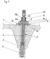
- the spark plug 2 has a shell 3 made of polytetrafluoroethylene (known under the trade name Teflon) and a center electrode 4 and includes the combustion chamber side, the insulator and the terminal electrode of a conventional spark plug 5.
- a locking mechanism with a screw 8 before.
- the screw 8 is formed on the one hand by a thread on the spark plug connector side part 7 of the locking mechanism and on the other hand by a thread on the engine block side part 6 of the locking mechanism.
- a splash-proof lid 9 is arranged, which also serves as a handle for screwing in and Ausschub of the spark plug.
- the spark plug connector-side part 7 is connected via a retaining sleeve 11 with the jacket 3 of the spark plug 2.
- the retaining sleeve 11 engages on the one hand on the bead 11a on the spark plug connector side part 7 and on the other hand with the beads 11b in recesses 13 of the shells 3 of the spark plug 2 a.
- Fig. 2 shows the embodiment of the invention of FIG. 1 in case of failure.
- the spark plug 5 has been imposed by positive pressure in the engine and collected by the spark plug 2.
- the degradation of the kinetic forces of the spark plug or the imposed parts thereof is essentially due to elastic and / or plastic deformation of the shell 3 of the spark plug 2.
- a part of kinetic energy is dissipated by the beads 11 b of the retaining sleeve 11 are torn out of the recesses 13 in the shell 3 of the spark plug 2.
- the shoulder 17 of the shell 3 is caught by the locking mechanism.
- locking mechanism and casing 3 do not change their relative position to each other in case of failure, but the energy purely by deformation of the spark plug, preferably its jacket 3 and the electrode 4 degraded becomes.
- a bayonet fitting for fastening the spark plug 2 to the engine block 1 is provided instead of a screw connection 8.
- the spark plug connector-side part 7 of Locking mechanism on the nose 15 of the bayonet lock which engages behind the engine block side part 6 of the locking mechanism in the locked position, so that the spark plug 2 is locked to the engine block 1.
- Fig. 4 shows the second embodiment of Fig. 3 in case of failure.
- the kinetic energy of the imposed spark plug parts is substantially reduced by deformation of the jacket material of the spark plug 2 and optionally the center electrode 4.
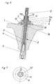
- a spring element 16 between the locking mechanism and shell 3 of the spark plug can be arranged. This can, as shown, be designed as a spiral spring, but also have other elastic material. In the fault case shown in Fig. 6, the spring element 16 is compressed, whereby the kinetic energy of the imposed spark plug parts is reduced.
- the pneumatic overpressure can, as in the other embodiments, escape via the Wegsamkeit 10.
- the jacket 3 is formed in two parts and the spring element is arranged therebetween.
- the spark plug 2 In large engines, preferably made of polytetrafluoroethylene jacket 3 of the spark plug 2 has a diameter between 2 cm and 3cm, preferably between 2.3 cm and 2.7 cm on.
- the length of the spark plug can be up to 30 cm and more in such engines.
- the present invention is not limited to the embodiments shown.
- the person skilled in the art can make a suitable selection from the already known with respect to both the materials and the locking mechanisms used.
- the sizing of the plug connector and the locking mechanism must then be tailored to the characteristics of the materials chosen so that the plug connector is designed in accordance with the invention.
- to be operated by hand locking mechanisms other operable with wrench or the like fasteners are conceivable, if deemed more favorable.
Landscapes
- Spark Plugs (AREA)
- Valve Device For Special Equipments (AREA)
- Valve-Gear Or Valve Arrangements (AREA)
Description
- Die vorliegende Erfindung betrifft eine Brennkraftmaschine, insbesondere einen stationären Gasmotor, mit mindestens einem an der Brennkraftmaschine befestigbaren Zündkerzenstecker sowie einen Zündkerzenstecker an sich.
- Die EP 0 530 883 schlägt vor, einen Zündkerzenstecker mittels einer Lasche und einer Schraube am Motorblock zu befestigen, um zu verhindern, dass der Zündkerzenstecker ungewollt von der Zündkerze abgezogen werden kann.
- Vor allem bei Großmotoren bzw. großen Brennkraftmaschinen, wie zum Beispiel stationären Gas-Otto-Motoren zum Antrieb von elektrischen Generatoren, kann es unter gewissen Umständen, bedingt durch Fertigungsfehler oder durch thermische oder mechanische Überlastung der Zündkerze, zum Ausdrücken des Keramikkörpers oder anderer Komponenten der Zündkerze aus dem Zündkerzengehäuse kommen. Diese Situation tritt üblicherweise bei sehr hohen Drücken im Brennraum des Motors auf. Im Fehlerfall werden die Komponenten der Zündkerze sehr stark durch den hohen Druck im Brennraum beschleunigt und aus dem Motor ausgeschossen. Dies bedeutet sowohl eine Gefährdung für sich in der Umgebung des Motors aufhaltende Menschen als auch für den Motor selber.
- Aufgabe der vorliegenden Erfindung ist es daher eine Brennkraftmaschine zu schaffen, bei der im Fehlerfall aus dem Motor herausgedrückte bzw. -geschossene Zündkerzen oder Zündkerzenteile durch eine technisch möglichst wenig aufwändige und einfach zu handhabende Konstruktion abgefangen werden.
- Dies wird erfindungsgemäß dadurch erreicht, dass der Zündkerzenstecker und seine Befestigung an der Brennkraftmaschine einer auf den Zündkerzenstecker ausgeübten Kraftbeaufschlagung, vorzugsweise in Längsrichtung des Zündkerzensteckers, von mindestens 1000 Newton standhalten.
- Durch die erfindungsgemäße Festigkeit des Zündkerzensteckers und Befestigung an der Brennkraftmaschine wird wirkungsvoll verhindert, dass im Fehlerfall einzelne Teile oder die gesamte Zündkerze aus dem Motor herausgedrückt bzw. -geschossen werden können. Sollte es zum Fehlerfall kommen, so können die herausgeschossenen Teile vom Zündkerzenstecker aufgefangen werden, da dieser einer entsprechenden Kraftbeaufschlagung standhält. Hierdurch ist eine Gefährdung von Mensch und Maschine durch aus dem Motor herausgeschossene Zündkerzen oder Teile davon wirkungsvoll verhindert. 1000 Newton entspricht hier ungefähr der maximalen Kraft, die auf eine Zündkerze bei Motoren mit Maximaldrücken von bis zu 100 bar im Brennraum wirkt.
- Bei Motoren mit höheren Maximaldrücken, sind der Zündkerzenstecker und seine Befestigung entsprechend stärker auszulegen. In diesem Fall ist es günstig, dass der Zündkerzenstecker und seine Befestigung an der Brennkraftmaschine einer auf den Zündkerzenstecker ausgeübten Kraftbeaufschlagung, vorzugsweise in Längsrichtung des Zündkerzensteckers, von mindestens 3000 Newton, vorzugsweise von mindestens 5000 Newton, standhalten. Dies gilt vor allem für Motoren, bei denen maximale Innendrücke von 250 bar bzw. von 300 bar im Brennraum herrschen. Darüber hinaus ist es günstig bei Motoren, mit entsprechend weit erhöhten Innendrücken im Brennraum, vorzusehen, dass der Zündkerzenstecker und seine Befestigung an der Brennkraftmaschine Kraftbeaufschlagungen von mindesten 7000 Newton bzw. von mindestens 10000 Newton standhalten.
- Da es beim Betrieb von Brennkraftmaschinen zum Aufheizen des Motorblocks und damit auch des Zündkerzensteckers sowie seiner Befestigung an der Brennkraftmaschine kommt, ist günstigerweise vorzusehen, dass der Zündkerzenstecker und seine Befestigung an der Brennkraftmaschine einer auf den Zündkerzenstecker ausgeübten Kraftbeaufschlagung in Höhe der oben angegebenen Werte bei Temperaturen bis zu 80° C, vorzugsweise bis zu 100° C, standhalten.
- Um eine einfache und schnelle Wartung der Zündkerzen zu ermöglichen, ist auf eine gute Zugänglichkeit zu achten. Daher sieht ein weiterer Aspekt der vorliegenden Erfindung vor, dass der Zündkerzenstecker an der Brennkraftmaschine mit einem werkzeuglos befestigbaren und lösbaren sowie formschlüssigen Verriegelungsmechanismus, vorzugsweise mit einem Bajonettverschluss oder mit einer Verschraubung, befestigbar ist. Durch diese Art der Befestigung ist zum einen ein schnelles Demontieren des Zündkerzensteckers per Hand möglich, zum anderen wird durch den formschlüssigen Verriegelungsmechanismus jedoch auch die nötige Festigkeit erreicht.
- Weitere Merkmale und Einzelheiten der vorliegenden Erfindung ergeben sich der nachfolgenden Figurenbeschreibung. Dabei zeigt:
- Fig. 1
- eine erste erfindungsgemäße Variante, bei der der Verriegelungsmechanismus eine Schraubverbindung aufweist,
- Fig. 2
- das erste Ausführungsbeispiel aus Fig. 1 im Fehlerfall,
- Fig. 3
- ein zweites Ausführungsbeispiel bei dem der Verriegelungsmechanismus einen Bajonettverschluss aufweist,
- Fig. 4
- das zweite Ausführungsbeispiel von Fig. 3 im Fehlerfall,
- Fig. 5
- ein drittes Ausführungsbeispiel mit einem Bajonettverschluss als Verriegelungsmechanismus und einem Federelement zur Dämpfung im Fehlerfall,
- Fig. 6
- das dritte Ausführungsbeispiel aus Fig. 5 im Fehlerfall,
- Fig. 7
- eine Draufsicht auf die drei Ausführungsbeispiele gemäß den Fig. 1 bis 6.
- Alle drei Ausführungsbeispiele gemäß den Fig. 1 bis 7 sind mittels eines lösbaren Verriegelungsmechanismus form- oder kraftschlüssig mit der Brennkraftmaschine verbunden. Die Befestigung erfolgt in den gezeigten Ausführungsbeispielen am Motorblock 1 bzw. der über den Zylinderkopf mit dem Motorblock 1 verbundenen Ventilhaube. Der Verriegelungsmechanismus weist im ersten Ausführungsbeispiel gemäß den Fig. 1 und 2 eine Verschraubung 8 und in den beiden weiteren Ausführungsbeispielen gemäß den Fig. 3 bis 6 einen Bajonettverschluss auf. Der Verriegelungsmechanismus wird so ausgeführt, dass die kinetischen und pneumatischen Kräfte im Fehlerfall des Ausdrückens bzw. -schießens einer Zündkerze gezielt abgebaut werden können.
- Die kinetische Energie der durch den hohen pneumatischen Druck aus dem Brennraum beschleunigten Komponenten der Zündkerze bzw. der Zündkerze selbst muss im Fehlerfall durch den Zündkerzenstecker 2 und seine Befestigung an der Brennkraftmaschine aufgenommen werden. Die kinetische Energie tritt hierbei in einer besonders hohen Belastungsspitze beim Lösen von Komponenten der Zündkerze oder beim Lösen der Zündkerze selbst auf. Der Abbau dieser Belastungsspitze wird vom Zündkerzenstecker 2 sowie seiner Befestigung am Motorblock (dem Verriegelungsmechanismus) gewährleistet. Der Abbau der kinetischen Energie kann durch Deformation des Mantels 3 des Zündkerzensteckers 2 und/oder durch zusätzlich am Zündkerzenstecker angeordnete Federelemente 16 gewährleistet werden. Die restliche Energie wird durch den form- oder kraftschlüssigen Verriegelungsmechanismus aufgenommen. Die Deformation kann elastisch erfolgen. Bei entsprechender Auslegung kann aber auch vorgesehen sein, dass der Mantel 3 und die Elektrode 4 im Fehlerfall plastisch verformt werden und anschließend ausgetauscht werden müssen. Hierbei werden günstigerweise nur die plastisch verformten Teile des Zündkerzensteckers 2 ausgetauscht und der Rest weiterverwendet.
- Bei den Ausführungsvarianten gemäß den Fig. 1 bis 4, bei denen die kinetische Energie im Wesentlichen durch elastische Verformung des Zündkerzensteckers abgebaut wird, weist der Mantel 3 des Zündkerzensteckers günstigerweise ein Elastizitätsmodul kleiner 2000 MPa, vorzugsweise kleiner 1000 MPa, auf. Es sind jedoch auch noch geringere Elastizitätsmodule kleiner 700 MPa oder kleiner 500 MPa denkbar. Zum Erreichen dieser Werte kann der Mantel zum Beispiel aus Polytetrafluorethylen, welches unter dem Handelsnamen Teflon verkauft wird, bestehen. Es sind jedoch auch andere Kunststoffe mit entsprechenden elastischen Eigenschaften und Festigkeitswerten denkbar. Generell muss der Fachmann das Material und die Dimensionen des Zündkerzensteckers so wählen, dass der Zündkerzenstecker der Kraftbeaufschlagung beim Ausschuss der Zündkerze bzw. von Teilen davon erfindungsgemäß standhält. Durch die Verwendung von Kunststoffen zur Herstellung des Mantels 3 des Zündkerzensteckers 2 wird darüber hinaus auch die elektrische Hochspannungsfestigkeit gewährleistet.
- Der Verriegelungsmechanismus wird günstigerweise aus einem Material, welches eine höhere Festigkeit bzw. Steifigkeit als der Mantel 3 aufweist, ausgeführt. Besonders bevorzugt sind Metalle zur Herstellung des Verriegelungsmechanismus.
- Bei der Zerstörung der Zündkerze kommt es zum Austritt des komprimierten Gases aus dem Brennraum des Motors. Die Angriffsfläche des Verriegelungsmechanismus ist in der Regel viel größer als die Angriffsfläche der Zündkerze, sodass zu befürchten wäre, dass der hohe pneumatische Druck aus dem Brennraum zur Überlastung des Verriegelungsmechanismus führen könnte. Um diese Überlastung durch die pneumatische Energie zu verhindern, wird ein gezielter Gasaustritt durch eine oder mehrere Gasaustrittsöffnungen bzw. Wegsamkeiten 10 im Verriegelungsmechanismus vorgesehen. Die gesamte Querschnittsfläche dieser Wegsamkeiten 10 wird so ausgelegt, dass das Gas im Fehlerfall selbst bei höchsten Druckverhältnissen im Brennraum so schnell entweichen kann, dass der Verriegelungsmechanismus durch die Summe der auf ihn wirkenden kinetischen und pneumatischen Kräfte nicht überlastet wird. Die Wegsamkeit 10 ist günstigerweise als Labyrinth gestaltet, wobei die Wegsamkeit spritzwasserfest, vorzugsweise vom Deckel 9, abgedeckt ist. Die Wegsamkeit 10 kann im Zündkerzenstecker 2 und/oder im Motorblock 1 und/oder zwischen Zündkerzenstecker 2 und Motorblock 1 angeordnet sein.
- Ein erstes Ausführungsbeispiel ist in Fig. 1 gezeigt. Der Zündkerzenstecker 2 weist eine Mantel 3 aus Polytetrafluorethylen (bekannt unter dem Handelsnamen Teflon) sowie einen Mittelelektrode 4 auf und umfasst brennkammerseitig den Isolator und die Anschlusselektrode einer an sich bekannten Zündkerze 5. Zur Befestigung am Motorblock 1 sieht der Zündkerzenstecker 2 einen Verriegelungsmechanismus mit einer Schraubverbindung 8 vor. Die Schraubverbindung 8 wird einerseits durch ein Gewinde am zündkerzensteckerseitigen Teil 7 des Verriegelungsmechanismus und andererseits durch ein Gewinde am motorblockseitigen Teil 6 des Verriegelungsmechanismus gebildet. Am zündkerzensteckerseitigen Teil 7 ist ein spritzwasserfester Deckel 9 angeordnet, welcher gleichzeitig als Handgriff zum Ein- und Ausschraubend des Zündkerzensteckers dient. Der zündkerzensteckerseitige Teil 7 ist über eine Haltemanschette 11 mit dem Mantel 3 des Zündkerzensteckers 2 verbunden. Die Haltemanschette 11 greift einerseits über die Wulst 11a am zündkerzensteckerseitigen Teil 7 und andererseits mit den Wulsten 11b in Ausnehmungen 13 der Mäntel 3 des Zündkerzensteckers 2 ein. Die Kontaktierung der Mittelelektrode 4 mit den Zündkabeln erfolgt mittels des Steckers 12 eines Zündkabels.
- Zum Abbau der pneumatischen Kräfte ist im Verriegelungsmechanismus die vom Deckel spritzwasserfest abgedeckte labyrinthartige Wegsamkeit 10 vorgesehen.
- Fig. 2 zeigt das erfindungsgemäße Ausführungsbeispiel aus Fig. 1 im Fehlerfall. Wie schematisch dargestellt, ist die Zündkerze 5 durch Überdruck im Motor ausgeschossen und vom Zündkerzenstecker 2 aufgefangen worden. Der Abbau der kinetischen Kräfte der Zündkerze bzw. der ausgeschossenen Teile davon erfolgt im Wesentlichen durch elastische und/oder plastische Deformation des Mantels 3 des Zündkerzensteckers 2. Darüber hinaus kann aber auch, wie in diesem Ausführungsbeispiel dargestellt, noch vorgesehen sein, dass ein Teil der kinetischen Energie abgebaut wird, indem die Wulste 11 b der Haltemanschette 11 aus den Ausnehmungen 13 im Mantel 3 des Zündkerzensteckers 2 herausgerissen werden. Bei dieser Variante ist dann vorgesehen, dass die Schulter 17 des Mantels 3 vom Verriegelungsmechanismus aufgefangen wird. Neben der in Fig. 1 und 2 gezeigten Variante ist es alternativ aber auch denkbar, dass Verriegelungsmechanismus und Mantel 3 im Fehlerfall Ihre relative Lage zueinander nicht verändern, sondern die Energie rein durch Deformation des Zündkerzensteckers, vorzugsweise seines Mantels 3 und der Elektrode 4, abgebaut wird.
- Im zweiten Ausführungsbeispiel gemäß den Fig. 3 und 4 ist anstelle einer Verschraubung 8 ein Bajonettverschluss zur Befestigung des Zündkerzensteckers 2 am Motorblock 1 vorgesehen. In dieser Ausführungsvariante weist der zündkerzensteckerseitige Teil 7 des Verriegelungsmechanismus die Nase 15 des Bajonettverschlusses auf, welche in der Verriegelungsstellung den motorblockseitigen Teil 6 des Verriegelungsmechanismus hintergreift, sodass der Zündkerzenstecker 2 mit dem Motorblock 1 verriegelt ist. Zur Betätigung weist der, wie an sich bekannt funktionierende Bajonettverschluss den mit der Nase 15 in Wirkverbindung stehenden Deckel 9 sowie eine Feder 14 auf. Fig. 4 zeigt das zweite Ausführungsbeispiel aus Fig. 3 im Fehlerfall.
- Bei den bisher diskutierten Ausführungsbeispielen gemäß den Fig. 1 bis 4 wird die kinetische Energie der ausgeschossenen Zündkerzenteile im Wesentlichen durch Deformation des Mantelmaterials des Zündkerzensteckers 2 sowie gegebenenfalls der Mittelelektrode 4 abgebaut. Alternativ hierzu kann, wie im dritten Ausführungsbeispiel gemäß den Fig. 5 und 6 gezeigt, auch ein Federelement 16 zwischen Verriegelungsmechanismus und Mantel 3 des Zündkerzensteckers angeordnet sein. Dies kann, wie dargestellt, als Spiralfeder ausgeführt sein, aber auch anderweitiges elastisches Material aufweisen. Im in Fig. 6 dargestellten Fehlerfall wird das Federelement 16 gestaucht, wodurch die kinetische Energie der ausgeschossenen Zündkerzenteile abgebaut wird. Der pneumatische Überdruck kann, wie in den anderen Ausführungsbeispielen auch, über die Wegsamkeit 10 entweichen. Bei der Anordnung des Federelementes 16 sind verschiedene Ausführungsvarianten denkbar. So kann auch vorgesehen sein, dass der Mantel 3 zweiteilig ausgebildet ist und das Federelement dazwischen angeordnet ist.
- Bei Großmotoren weist der, vorzugsweise aus Polytetrafluorethylen gefertigte Mantel 3 des Zündkerzensteckers 2 einen Durchmesser zwischen 2 cm und 3cm, vorzugsweise zwischen 2,3 cm und 2,7 cm, auf. Die Länge der Zündkerzenstecker kann bei solchen Motoren bis zu 30 cm und mehr betragen.
- Die vorliegende Erfindung ist nicht auf die gezeigten Ausführungsbeispiele beschränkt. Der Fachmann kann sowohl bezüglich der Materialen als auch der verwendeten Verriegelungsmechanismen eine geeignete Auswahl aus dem bereits Bekannten treffen. Die Dimensionierung des Zündkerzensteckers und des Verriegelungsmechanismus muss dann auf die Eigenschaften der gewählten Materialien so abgestimmt werden, dass der Zündkerzenstecker erfindungsgemäß ausgelegt wird. Neben den in den Ausführungsbeispielen gezeigten, von Hand zu betätigenden Verriegelungsmechanismen sind auch andere mit Schraubenschlüssel oder dergleichen betätigbare Befestigungseinrichtungen denkbar, wenn dies für günstiger erachtet wird.
Claims (11)
- Brennkraftmaschine, insbesondere stationärer Gasmotor, mit mindestens einem an der Brennkraftmaschine befestigbaren Zündkerzenstecker, dadurch gekennzeichnet, dass der Zündkerzenstecker (2) und seine Befestigung an der Brennkraftmaschine einer auf den Zündkerzenstecker (2) ausgeübten Kraftbeaufschlagung, vorzugsweise in Längsrichtung des Zündkerzensteckers (2), von mindestens 1000 Newton standhalten.
- Brennkraftmaschine nach Anspruch 1, dadurch gekennzeichnet, dass der Zündkerzenstecker (2) und seine Befestigung an der Brennkraftmaschine einer auf den Zündkerzenstecker (2) ausgeübten Kraftbeaufschlagung, vorzugsweise in Längsrichtung des Zündkerzensteckers (2), von mindestens 3000 Newton, vorzugsweise von mindestens 5000 Newton, standhalten.
- Brennkraftmaschine nach Anspruch 1 oder 2, dadurch gekennzeichnet, dass der Zündkerzenstecker (2) und seine Befestigung an der Brennkraftmaschine einer auf den Zündkerzenstecker (2) ausgeübten Kraftbeaufschlagung in Höhe der in Anspruch 1 oder 2 angegebenen Werte bei Temperaturen bis zu 80° C, vorzugsweise bis zu 100° C, standhalten.
- Brennkraftmaschine nach einem der Ansprüche 1 bis 3, dadurch gekennzeichnet, dass der Zündkerzenstecker (2) an der Brennkraftmaschine mit einem werkzeuglos befestigbaren und lösbaren sowie formschlüssigen Verriegelungsmechanismus, vorzugsweise mit einem Bajonettverschluss oder mit einer Verschraubung (8), befestigbar ist
- Brennkraftmaschine nach einem der Ansprüche 1 bis 4, wobei der Zündkerzenstecker eine Ummantelung und einen Verriegelungsmechanismus aufweist, dadurch gekennzeichnet, dass der Verriegelungsmechanismus eine höhere Steifigkeit als die Ummantelung (3) aufweist.
- Brennkraftmaschine nach einem der Ansprüche 1 bis 5, wobei der Zündkirzenstecker eine Ummantelung aufweist, dadurch gekennzeichnet, dass die Ummantelung (3) ein Elastizitätsmodul kleiner 2000 MPa, vorzugsweise kleiner 1000 MPa, aufweist.
- Brennkraftmaschine nach einem der Ansprüche 1 bis 5, wobei der Zündkerzenstecker eine Ummantelung aufweist, dadurch gekennzeichnet, dass die Ummantelung (3) ein Elastizitätsmodul kleiner 700 MPa, vorzugsweise kleiner 500 MPa, aufweist.
- Brennkraftmaschine nach einem der Ansprüche 1 bis 7, wobei der Zündkerzenstecker eine Ummantelung aufweist, dadurch gekennzeichnet, dass an der Ummantelung (3) ein Federelement (16) angeordnet ist.
- Brennkraftmaschine nach einem der Ansprüche 1 bis 8, wobei der Zündkerzenstecker eine Ummantelung aufweist, dadurch gekennzeichnet, dass die Ummantelung (3) Polytetrafluorethylene aufweist.
- Brennkraftmaschine nach einem der Ansprüche 1 bis 9, dadurch gekennzeichnet, dass im Zündkerzenstecker (2) und/oder in der Brennkraftmaschine und/oder zwischen Zündkerzenstecker (2) und Brennkraftmaschine mindestens eine, vorzugsweise labyrinthartige, Wegsamkeit (10) für entweichendes Gas angeordnet ist.
- Brennkraftmaschine nach Anspruch 10, dadurch gekennzeichnet, dass die Wegsamkeit (10) spritzwasserfest abgedeckt ist.
Priority Applications (1)
| Application Number | Priority Date | Filing Date | Title |
|---|---|---|---|
| AT04012982T ATE357762T1 (de) | 2003-06-04 | 2004-06-02 | Brennkraftmaschine |
Applications Claiming Priority (2)
| Application Number | Priority Date | Filing Date | Title |
|---|---|---|---|
| AT8642003 | 2003-06-04 | ||
| AT8642003 | 2003-06-04 |
Publications (2)
| Publication Number | Publication Date |
|---|---|
| EP1484826A1 EP1484826A1 (de) | 2004-12-08 |
| EP1484826B1 true EP1484826B1 (de) | 2007-03-21 |
Family
ID=33136524
Family Applications (1)
| Application Number | Title | Priority Date | Filing Date |
|---|---|---|---|
| EP04012982A Expired - Lifetime EP1484826B1 (de) | 2003-06-04 | 2004-06-02 | Brennkraftmaschine |
Country Status (5)
| Country | Link |
|---|---|
| US (1) | US7146957B2 (de) |
| EP (1) | EP1484826B1 (de) |
| AT (1) | ATE357762T1 (de) |
| DE (1) | DE502004003255D1 (de) |
| ES (1) | ES2283904T3 (de) |
Families Citing this family (2)
| Publication number | Priority date | Publication date | Assignee | Title |
|---|---|---|---|---|
| DE102004030790B4 (de) * | 2004-06-25 | 2009-07-02 | Deutz Power Systems Gmbh | Zündkerze mit Zündkabel |
| JP2012256489A (ja) * | 2011-06-08 | 2012-12-27 | Ngk Insulators Ltd | 点火部品 |
Family Cites Families (34)
| Publication number | Priority date | Publication date | Assignee | Title |
|---|---|---|---|---|
| DE760104C (de) * | 1940-11-21 | 1952-10-20 | Carl F W Borgward | Zylinderkopf fuer Brennkraftmaschinen |
| US3697796A (en) | 1970-07-27 | 1972-10-10 | Russell G Livingston | Spark plug shielding |
| CA1105582A (en) * | 1978-02-03 | 1981-07-21 | Yukitsugu Fukumori | Device for electrically connecting spark plug to high- voltage cable |
| US4715337A (en) | 1985-01-31 | 1987-12-29 | Caterpillar Inc. | Engine ignition system with an insulated and extendable extender |
| DE3920080C2 (de) * | 1989-06-20 | 1994-08-04 | Audi Ag | Zündvorrichtung für eine Brennkraftmaschine |
| GB2241739B (en) | 1990-03-09 | 1994-11-23 | Cooper Ind Inc | Igniter and cable connector assembly |
| US5127840A (en) * | 1991-09-03 | 1992-07-07 | General Motors Corporation | Spark plug connector |
| US5377640A (en) * | 1992-07-23 | 1995-01-03 | Sumitomo Wiring Systems, Ltd. | Plug cap device |
| US5385686A (en) * | 1993-06-14 | 1995-01-31 | General Motors Corporation | Spark plug boot with improved lubricant |
| JP2602711Y2 (ja) * | 1993-10-13 | 2000-01-24 | 矢崎総業株式会社 | 点火プラグ取り付け孔のレインカバー |
| JPH0729792U (ja) * | 1993-11-01 | 1995-06-02 | 住友電装株式会社 | プラグキャップの空気抜き構造 |
| DE4340616A1 (de) * | 1993-11-29 | 1995-06-01 | Bmw Rolls Royce Gmbh | Befestigungsanordnung einer Zündkerze einer Gasturbine |
| JP2914195B2 (ja) * | 1994-10-14 | 1999-06-28 | 住友電装株式会社 | 内燃機関のプラグキャップ |
| JPH08124651A (ja) * | 1994-10-24 | 1996-05-17 | Sumitomo Wiring Syst Ltd | 点火ケーブル用プラグキャップ |
| JP3556725B2 (ja) * | 1995-03-20 | 2004-08-25 | 三菱電機株式会社 | 内燃機関の点火装置 |
| US5577921A (en) | 1995-06-16 | 1996-11-26 | Caterpillar Inc. | Electrical connector system for electrically connecting a voltage source to a spark plug terminal |
| JPH09106878A (ja) | 1995-10-12 | 1997-04-22 | Sumitomo Wiring Syst Ltd | プラグキャップの空気抜き構造 |
| JP3489925B2 (ja) * | 1995-10-13 | 2004-01-26 | 三菱電機株式会社 | 内燃機関の点火装置 |
| JPH09129355A (ja) | 1995-11-01 | 1997-05-16 | Yazaki Corp | 点火プラグ用プラグキャップ |
| JP3417756B2 (ja) * | 1996-03-22 | 2003-06-16 | 矢崎総業株式会社 | プラグキャップ用レインカバー |
| DE19611283C1 (de) * | 1996-03-22 | 1997-10-23 | Florian Virchow | Zündkerzenstecker für einen Verbrennungsmotor |
| JP3361704B2 (ja) * | 1996-10-25 | 2003-01-07 | 矢崎総業株式会社 | 点火プラグ用プラグキャップ |
| JPH1154238A (ja) | 1997-08-04 | 1999-02-26 | Yazaki Corp | 点火プラグ用プラグキャップ |
| US5799633A (en) * | 1997-08-08 | 1998-09-01 | Lexington Insulators | Electrical insulator with a duckbill-shaped valve |
| US6635605B1 (en) * | 1998-06-12 | 2003-10-21 | Dow Corning Corporation | Dielectric lubricant and spark plug boot including the same |
| JP2000323258A (ja) | 1999-05-10 | 2000-11-24 | Yazaki Corp | 点火プラグ用プラグキャップ |
| US6193528B1 (en) * | 2000-05-01 | 2001-02-27 | Delphi Technologies, Inc. | Cam lock spark plug wire connection |
| JP4445107B2 (ja) * | 2000-08-10 | 2010-04-07 | 日本特殊陶業株式会社 | コイル一体型点火プラグの取付構造およびコイル一体型点火プラグ |
| JP4287034B2 (ja) * | 2000-08-31 | 2009-07-01 | 矢崎総業株式会社 | プラグキャップの換気構造 |
| US6467447B1 (en) * | 2001-07-17 | 2002-10-22 | Delphi Technologies, Inc. | Spark plug boot keeper assembly |
| US6427674B1 (en) * | 2001-09-24 | 2002-08-06 | Daimlerchrysler Corporation | Socket coil-on-plug retainer |
| US20050066776A1 (en) * | 2003-09-30 | 2005-03-31 | Ward Gregory E. | Damaged spark/glow plug removal tool |
| US6926266B1 (en) * | 2004-02-13 | 2005-08-09 | Delphi Technologies, Inc. | Shock absorbing assembly for a pencil ignition coil |
| US7185622B2 (en) * | 2004-03-12 | 2007-03-06 | Doll Martin J | Method and apparatus for interconnecting a coil and a spark plug |
-
2004
- 2004-06-02 AT AT04012982T patent/ATE357762T1/de active
- 2004-06-02 DE DE502004003255T patent/DE502004003255D1/de not_active Expired - Lifetime
- 2004-06-02 ES ES04012982T patent/ES2283904T3/es not_active Expired - Lifetime
- 2004-06-02 EP EP04012982A patent/EP1484826B1/de not_active Expired - Lifetime
- 2004-06-04 US US10/861,024 patent/US7146957B2/en not_active Expired - Lifetime
Also Published As
| Publication number | Publication date |
|---|---|
| ES2283904T3 (es) | 2007-11-01 |
| DE502004003255D1 (de) | 2007-05-03 |
| EP1484826A1 (de) | 2004-12-08 |
| US20040244753A1 (en) | 2004-12-09 |
| US7146957B2 (en) | 2006-12-12 |
| ATE357762T1 (de) | 2007-04-15 |
Similar Documents
| Publication | Publication Date | Title |
|---|---|---|
| DE102008022982B4 (de) | Hochspannungsverriegelungsverbindung | |
| DE112011105024B4 (de) | Isolierratsche | |
| DE2934706A1 (de) | Elektrischer verbinder | |
| DE112016005983B4 (de) | Ultraschallsensor | |
| EP3133303B1 (de) | Blindnietelement | |
| DE102016206378A1 (de) | Verbindungsanordnung eines ersten Bauelements an einem zweiten Bauelement, insbesondere für ein Fahrzeug, sowie Verbindungsvorrichtung, insbesondere für ein Fahrzeug | |
| DE112009000215T5 (de) | Masseabschirmung mit hohem Gewinde | |
| EP1443296B1 (de) | Pyromechanisches Trennelement | |
| DE69401123T2 (de) | Kabeleinführung | |
| DE102018208029B4 (de) | Anschlussvorrichtung | |
| EP2816683A1 (de) | Mehrfachfunkenstrecke | |
| WO2017050725A1 (de) | Vorrichtung zur drehmomentbegrenzung | |
| DE102013005092A1 (de) | Verbindersystem zum mechanischen Verbinden und elektrischen Kontaktieren von zwei elektrisch leitfähigen Komponenten | |
| DE102016223789B3 (de) | Gehäuse zur Verwendung eines elektronischen Geräts in einem explosionsgefährdeten Bereich | |
| DE102017108929A1 (de) | Belastungssensor | |
| EP1484826A1 (de) | Brennkraftmaschine | |
| DE102012104397B4 (de) | Vorrichtung und Verfahren zum Koppeln von einem Anbaugerät an einem Fahrzeug | |
| DE102020111765B4 (de) | Elektrische Sicherungsvorrichtung, Verfahren zur Herstellung einer Sicherungsvorrichtung und ein Verfahren zum Betrieb einer elektrischen Sicherungsvorrichtung | |
| AT8317U1 (de) | Brennkraftmaschine | |
| EP0546637B1 (de) | Kombination aus einer elektrischen Verbindungsdose und einer Überwurfmutter | |
| DE102016209446B4 (de) | Verfahren zur Modifizierung eines Prozesswerkzeugs zur Reduzierung dessen Gefahrenpotentials, mechanische Sicherungsvorrichtung für ein Prozesswerkzeug in Verbindung mit einem sicheren Roboter | |
| EP3551403B1 (de) | Austrennwerkzeug | |
| DE102018121850A1 (de) | Steckerschutzvorrichtung und Sensoranordnung mit einer solchen Steckerschutzvorrichtung | |
| DE102013214836B4 (de) | Rundsteckverbinder mit Schlagschutz | |
| EP1267461B1 (de) | Zündkerze |
Legal Events
| Date | Code | Title | Description |
|---|---|---|---|
| PUAI | Public reference made under article 153(3) epc to a published international application that has entered the european phase |
Free format text: ORIGINAL CODE: 0009012 |
|
| AK | Designated contracting states |
Kind code of ref document: A1 Designated state(s): AT BE BG CH CY CZ DE DK EE ES FI FR GB GR HU IE IT LI LU MC NL PL PT RO SE SI SK TR |
|
| AX | Request for extension of the european patent |
Extension state: AL HR LT LV MK |
|
| 17P | Request for examination filed |
Effective date: 20041124 |
|
| 17Q | First examination report despatched |
Effective date: 20050406 |
|
| AKX | Designation fees paid |
Designated state(s): AT BE BG CH CY CZ DE DK EE ES FI FR GB GR HU IE IT LI LU MC NL PL PT RO SE SI SK TR |
|
| GRAP | Despatch of communication of intention to grant a patent |
Free format text: ORIGINAL CODE: EPIDOSNIGR1 |
|
| GRAS | Grant fee paid |
Free format text: ORIGINAL CODE: EPIDOSNIGR3 |
|
| GRAA | (expected) grant |
Free format text: ORIGINAL CODE: 0009210 |
|
| AK | Designated contracting states |
Kind code of ref document: B1 Designated state(s): AT BE BG CH CY CZ DE DK EE ES FI FR GB GR HU IE IT LI LU MC NL PL PT RO SE SI SK TR |
|
| PG25 | Lapsed in a contracting state [announced via postgrant information from national office to epo] |
Ref country code: PL Free format text: LAPSE BECAUSE OF FAILURE TO SUBMIT A TRANSLATION OF THE DESCRIPTION OR TO PAY THE FEE WITHIN THE PRESCRIBED TIME-LIMIT Effective date: 20070321 Ref country code: FI Free format text: LAPSE BECAUSE OF FAILURE TO SUBMIT A TRANSLATION OF THE DESCRIPTION OR TO PAY THE FEE WITHIN THE PRESCRIBED TIME-LIMIT Effective date: 20070321 Ref country code: IE Free format text: LAPSE BECAUSE OF FAILURE TO SUBMIT A TRANSLATION OF THE DESCRIPTION OR TO PAY THE FEE WITHIN THE PRESCRIBED TIME-LIMIT Effective date: 20070321 Ref country code: SI Free format text: LAPSE BECAUSE OF FAILURE TO SUBMIT A TRANSLATION OF THE DESCRIPTION OR TO PAY THE FEE WITHIN THE PRESCRIBED TIME-LIMIT Effective date: 20070321 |
|
| REG | Reference to a national code |
Ref country code: GB Ref legal event code: FG4D Free format text: NOT ENGLISH |
|
| REG | Reference to a national code |
Ref country code: CH Ref legal event code: EP |
|
| REF | Corresponds to: |
Ref document number: 502004003255 Country of ref document: DE Date of ref document: 20070503 Kind code of ref document: P |
|
| REG | Reference to a national code |
Ref country code: IE Ref legal event code: FG4D Free format text: LANGUAGE OF EP DOCUMENT: GERMAN |
|
| PG25 | Lapsed in a contracting state [announced via postgrant information from national office to epo] |
Ref country code: SE Free format text: LAPSE BECAUSE OF FAILURE TO SUBMIT A TRANSLATION OF THE DESCRIPTION OR TO PAY THE FEE WITHIN THE PRESCRIBED TIME-LIMIT Effective date: 20070621 |
|
| GBT | Gb: translation of ep patent filed (gb section 77(6)(a)/1977) |
Effective date: 20070620 |
|
| PG25 | Lapsed in a contracting state [announced via postgrant information from national office to epo] |
Ref country code: PT Free format text: LAPSE BECAUSE OF FAILURE TO SUBMIT A TRANSLATION OF THE DESCRIPTION OR TO PAY THE FEE WITHIN THE PRESCRIBED TIME-LIMIT Effective date: 20070821 |
|
| ET | Fr: translation filed | ||
| REG | Reference to a national code |
Ref country code: IE Ref legal event code: FD4D |
|
| REG | Reference to a national code |
Ref country code: ES Ref legal event code: FG2A Ref document number: 2283904 Country of ref document: ES Kind code of ref document: T3 |
|
| PG25 | Lapsed in a contracting state [announced via postgrant information from national office to epo] |
Ref country code: SK Free format text: LAPSE BECAUSE OF FAILURE TO SUBMIT A TRANSLATION OF THE DESCRIPTION OR TO PAY THE FEE WITHIN THE PRESCRIBED TIME-LIMIT Effective date: 20070321 |
|
| BERE | Be: lapsed |
Owner name: GE JENBACHER GMBH & CO. OHG Effective date: 20070630 |
|
| PG25 | Lapsed in a contracting state [announced via postgrant information from national office to epo] |
Ref country code: CZ Free format text: LAPSE BECAUSE OF FAILURE TO SUBMIT A TRANSLATION OF THE DESCRIPTION OR TO PAY THE FEE WITHIN THE PRESCRIBED TIME-LIMIT Effective date: 20070321 Ref country code: RO Free format text: LAPSE BECAUSE OF FAILURE TO SUBMIT A TRANSLATION OF THE DESCRIPTION OR TO PAY THE FEE WITHIN THE PRESCRIBED TIME-LIMIT Effective date: 20070321 |
|
| PLBE | No opposition filed within time limit |
Free format text: ORIGINAL CODE: 0009261 |
|
| STAA | Information on the status of an ep patent application or granted ep patent |
Free format text: STATUS: NO OPPOSITION FILED WITHIN TIME LIMIT |
|
| PG25 | Lapsed in a contracting state [announced via postgrant information from national office to epo] |
Ref country code: DK Free format text: LAPSE BECAUSE OF FAILURE TO SUBMIT A TRANSLATION OF THE DESCRIPTION OR TO PAY THE FEE WITHIN THE PRESCRIBED TIME-LIMIT Effective date: 20070321 Ref country code: MC Free format text: LAPSE BECAUSE OF NON-PAYMENT OF DUE FEES Effective date: 20070630 |
|
| 26N | No opposition filed |
Effective date: 20071227 |
|
| PG25 | Lapsed in a contracting state [announced via postgrant information from national office to epo] |
Ref country code: BE Free format text: LAPSE BECAUSE OF NON-PAYMENT OF DUE FEES Effective date: 20070630 |
|
| PG25 | Lapsed in a contracting state [announced via postgrant information from national office to epo] |
Ref country code: GR Free format text: LAPSE BECAUSE OF FAILURE TO SUBMIT A TRANSLATION OF THE DESCRIPTION OR TO PAY THE FEE WITHIN THE PRESCRIBED TIME-LIMIT Effective date: 20070622 |
|
| PG25 | Lapsed in a contracting state [announced via postgrant information from national office to epo] |
Ref country code: EE Free format text: LAPSE BECAUSE OF FAILURE TO SUBMIT A TRANSLATION OF THE DESCRIPTION OR TO PAY THE FEE WITHIN THE PRESCRIBED TIME-LIMIT Effective date: 20070321 |
|
| REG | Reference to a national code |
Ref country code: CH Ref legal event code: PL |
|
| PG25 | Lapsed in a contracting state [announced via postgrant information from national office to epo] |
Ref country code: CH Free format text: LAPSE BECAUSE OF NON-PAYMENT OF DUE FEES Effective date: 20080630 Ref country code: LI Free format text: LAPSE BECAUSE OF NON-PAYMENT OF DUE FEES Effective date: 20080630 |
|
| PG25 | Lapsed in a contracting state [announced via postgrant information from national office to epo] |
Ref country code: CY Free format text: LAPSE BECAUSE OF FAILURE TO SUBMIT A TRANSLATION OF THE DESCRIPTION OR TO PAY THE FEE WITHIN THE PRESCRIBED TIME-LIMIT Effective date: 20070321 |
|
| PG25 | Lapsed in a contracting state [announced via postgrant information from national office to epo] |
Ref country code: BG Free format text: LAPSE BECAUSE OF FAILURE TO SUBMIT A TRANSLATION OF THE DESCRIPTION OR TO PAY THE FEE WITHIN THE PRESCRIBED TIME-LIMIT Effective date: 20070621 Ref country code: LU Free format text: LAPSE BECAUSE OF NON-PAYMENT OF DUE FEES Effective date: 20070602 |
|
| PG25 | Lapsed in a contracting state [announced via postgrant information from national office to epo] |
Ref country code: HU Free format text: LAPSE BECAUSE OF FAILURE TO SUBMIT A TRANSLATION OF THE DESCRIPTION OR TO PAY THE FEE WITHIN THE PRESCRIBED TIME-LIMIT Effective date: 20070922 Ref country code: TR Free format text: LAPSE BECAUSE OF FAILURE TO SUBMIT A TRANSLATION OF THE DESCRIPTION OR TO PAY THE FEE WITHIN THE PRESCRIBED TIME-LIMIT Effective date: 20070321 |
|
| REG | Reference to a national code |
Ref country code: FR Ref legal event code: PLFP Year of fee payment: 13 |
|
| REG | Reference to a national code |
Ref country code: FR Ref legal event code: PLFP Year of fee payment: 14 |
|
| REG | Reference to a national code |
Ref country code: FR Ref legal event code: PLFP Year of fee payment: 15 |
|
| PGFP | Annual fee paid to national office [announced via postgrant information from national office to epo] |
Ref country code: NL Payment date: 20190527 Year of fee payment: 16 |
|
| PGFP | Annual fee paid to national office [announced via postgrant information from national office to epo] |
Ref country code: MC Payment date: 20190520 Year of fee payment: 5 Ref country code: ES Payment date: 20190701 Year of fee payment: 16 |
|
| PGFP | Annual fee paid to national office [announced via postgrant information from national office to epo] |
Ref country code: FR Payment date: 20200520 Year of fee payment: 17 Ref country code: DE Payment date: 20200519 Year of fee payment: 17 |
|
| PGFP | Annual fee paid to national office [announced via postgrant information from national office to epo] |
Ref country code: GB Payment date: 20200525 Year of fee payment: 17 Ref country code: IT Payment date: 20200519 Year of fee payment: 17 |
|
| REG | Reference to a national code |
Ref country code: NL Ref legal event code: MM Effective date: 20200701 |
|
| REG | Reference to a national code |
Ref country code: AT Ref legal event code: MM01 Ref document number: 357762 Country of ref document: AT Kind code of ref document: T Effective date: 20200602 |
|
| PG25 | Lapsed in a contracting state [announced via postgrant information from national office to epo] |
Ref country code: NL Free format text: LAPSE BECAUSE OF NON-PAYMENT OF DUE FEES Effective date: 20200701 |
|
| PG25 | Lapsed in a contracting state [announced via postgrant information from national office to epo] |
Ref country code: AT Free format text: LAPSE BECAUSE OF NON-PAYMENT OF DUE FEES Effective date: 20200602 |
|
| REG | Reference to a national code |
Ref country code: ES Ref legal event code: FD2A Effective date: 20211026 |
|
| REG | Reference to a national code |
Ref country code: DE Ref legal event code: R119 Ref document number: 502004003255 Country of ref document: DE |
|
| PG25 | Lapsed in a contracting state [announced via postgrant information from national office to epo] |
Ref country code: ES Free format text: LAPSE BECAUSE OF NON-PAYMENT OF DUE FEES Effective date: 20200603 |
|
| GBPC | Gb: european patent ceased through non-payment of renewal fee |
Effective date: 20210602 |
|
| PG25 | Lapsed in a contracting state [announced via postgrant information from national office to epo] |
Ref country code: GB Free format text: LAPSE BECAUSE OF NON-PAYMENT OF DUE FEES Effective date: 20210602 Ref country code: DE Free format text: LAPSE BECAUSE OF NON-PAYMENT OF DUE FEES Effective date: 20220101 |
|
| PG25 | Lapsed in a contracting state [announced via postgrant information from national office to epo] |
Ref country code: FR Free format text: LAPSE BECAUSE OF NON-PAYMENT OF DUE FEES Effective date: 20210630 |
|
| PG25 | Lapsed in a contracting state [announced via postgrant information from national office to epo] |
Ref country code: IT Free format text: LAPSE BECAUSE OF NON-PAYMENT OF DUE FEES Effective date: 20210602 |