EP1480283B1 - Batteriekasten - Google Patents
Batteriekasten Download PDFInfo
- Publication number
- EP1480283B1 EP1480283B1 EP04011897A EP04011897A EP1480283B1 EP 1480283 B1 EP1480283 B1 EP 1480283B1 EP 04011897 A EP04011897 A EP 04011897A EP 04011897 A EP04011897 A EP 04011897A EP 1480283 B1 EP1480283 B1 EP 1480283B1
- Authority
- EP
- European Patent Office
- Prior art keywords
- battery box
- opening
- cord
- protrusion
- section
- Prior art date
- Legal status (The legal status is an assumption and is not a legal conclusion. Google has not performed a legal analysis and makes no representation as to the accuracy of the status listed.)
- Expired - Lifetime
Links
- 230000037431 insertion Effects 0.000 claims description 23
- 238000003780 insertion Methods 0.000 claims description 23
- 230000003014 reinforcing effect Effects 0.000 claims description 4
- 239000007858 starting material Substances 0.000 description 6
- 238000009434 installation Methods 0.000 description 3
- XLYOFNOQVPJJNP-UHFFFAOYSA-N water Substances O XLYOFNOQVPJJNP-UHFFFAOYSA-N 0.000 description 2
- 230000001133 acceleration Effects 0.000 description 1
- 239000002253 acid Substances 0.000 description 1
- 230000015572 biosynthetic process Effects 0.000 description 1
- 230000036461 convulsion Effects 0.000 description 1
- 238000010137 moulding (plastic) Methods 0.000 description 1
- 238000007665 sagging Methods 0.000 description 1
Images

Classifications
-
- H—ELECTRICITY
- H01—ELECTRIC ELEMENTS
- H01M—PROCESSES OR MEANS, e.g. BATTERIES, FOR THE DIRECT CONVERSION OF CHEMICAL ENERGY INTO ELECTRICAL ENERGY
- H01M50/00—Constructional details or processes of manufacture of the non-active parts of electrochemical cells other than fuel cells, e.g. hybrid cells
- H01M50/20—Mountings; Secondary casings or frames; Racks, modules or packs; Suspension devices; Shock absorbers; Transport or carrying devices; Holders
- H01M50/256—Carrying devices, e.g. belts
-
- Y—GENERAL TAGGING OF NEW TECHNOLOGICAL DEVELOPMENTS; GENERAL TAGGING OF CROSS-SECTIONAL TECHNOLOGIES SPANNING OVER SEVERAL SECTIONS OF THE IPC; TECHNICAL SUBJECTS COVERED BY FORMER USPC CROSS-REFERENCE ART COLLECTIONS [XRACs] AND DIGESTS
- Y02—TECHNOLOGIES OR APPLICATIONS FOR MITIGATION OR ADAPTATION AGAINST CLIMATE CHANGE
- Y02E—REDUCTION OF GREENHOUSE GAS [GHG] EMISSIONS, RELATED TO ENERGY GENERATION, TRANSMISSION OR DISTRIBUTION
- Y02E60/00—Enabling technologies; Technologies with a potential or indirect contribution to GHG emissions mitigation
- Y02E60/10—Energy storage using batteries
Definitions
- the invention relates to a battery box with a passage opening a flange of the battery box for receiving a handle element, the has an elongated handle portion which is larger than the passage opening, and a loop attached to the ends of the handle portion String section has.
- handles For handling of batteries, especially of car batteries, are carrying handles known, for example, as plastic moldings hinged to the battery cover be clamped. Such folding handles are for example from the EP 1 164 647 A2.
- German utility model G 88 05 405.5 U1 is a handle for battery boxes disclosed in the locking chambers for the end pieces of the battery box cord are introduced. After threading through the battery box cord through the through holes in the flange of the battery box are the ends the battery box cord then by clamping the end pieces in the locking chamber connected to the handle.
- a carrying device for a rechargeable battery is disclosed, the retractable attached to the accumulator carrying handles, which by provided on opposite sides of the accumulator guide slots hin tellsteckbar and are held in the support position with the handle pulled out.
- the handle is designed as a rectangular frame made of plastic, which in one Led bar with a guide slot. At the lower horizontal frame section projections are provided, and with the handle pulled out hit the lower edge of the bar.
- DE 7135447 U is an accumulator described with a attached to a handle plastic cord handle, the in feedthrough holes and slotted Einknöpfungslöchern a handle bar is recorded with ribs.
- WO 01/41 236 A1 is a carrying handle for a battery cord with a Einfädelungsö réelle described.
- the battery must pass through two holes be threaded into a support bar on the battery box. Subsequently, will secured to the locking element on the carrying handle, so that battery and Carrying handle are closed.
- the object of the invention is therefore to provide an improved battery box, be mounted on the with little installation effort carrying handle elements can, which are also highly resilient.
- the object is according to the invention in a generic battery box achieved in that the passage opening as a in a longitudinal direction extending slot is formed through which the loop of the cord section the tag handle element is feasible.
- At the battery box below the opening of the slot in the slot ends is one each Clamp locking element arranged to receive the cord section.
- the Klemmverriegelungsiata each have an insertion opening, which in a Guide opening for the cord section opens and opposite the guide opening an open to the introduction of the cord section insertion side and a constriction for lockingly receiving the cord section in the adjacent one Has guide opening.
- the open insertion side is parallel in the longitudinal direction seen to the slot from the slot in the direction of the assigned slot end.
- the slot thus forms a limit to the battery box string outside through the slot ends.
- the limitation on the guidance of the battery box cord inward, however, is independent of the slot Lock locking elements causes, with the open insertion side in the direction the respectively assigned slot end points.
- the loop of the cord section of a ring-closed Battery box cord with handle section and cord section easily through the Long hole to be guided.
- the passage of the loop through a slot is much easier and faster than threading battery box cord ends through the conventional through holes, which is only about the Diameter of the battery box cord corresponding diameter.
- the Loop is then placed around the clamp locking elements so that Cord sections in the region of the open Ein slaughterchemchemchem the insertion of the Clamp locking elements lie.
- the cord section is then automatically pulled into the adjacent guide opening through the insertion opening and by the narrowing of the insertion opening in the guide opening held.
- This embodiment of the battery box according to the invention has the advantage that no fasteners on the battery box cord are required. This can rather be molded in one piece, so that the resilience essential is increased.
- a projection formed integrally with the battery box is provided, extending transversely to the outer wall of the battery box and parallel in the longitudinal direction of the flange extends.
- the clamping locking elements are included each in the narrow adjacent to the battery box sides of the projection shaped. This has the advantage that the battery box cord below the projection can rest when the battery box cord with the handle portion is pulled up.
- reinforcing ribs are transverse to Provided longitudinally of the projection, which is integral with the projection and connected to the battery box.
- At least one opposite of the container wall provided on the underside of the projection arranged nose, which points in the direction running from the flange to the projection downwards. Through the nose slipping the battery box cord from the projection prevents and ensures that the battery box cord is also at extreme Load is safely seated in the clamping locking elements.
- FIG. 1 shows a side view of a detail of a starter battery 1 for Detecting motor vehicles, in a known manner, a battery box 2 with a the battery box 2 top closing lid 3 has. Through the lid 3 are the poles 4 led to the electrical connection and there are plugs 5 to Checking the water and acidity and, if necessary, refilling Water and / or acid provided.
- a flange 6 is formed, which is of the lid. 3 is overruled.
- a passage opening for receiving a carrying handle element 7 is formed in the flange 6 .
- the carrying handle element 7 consists of this an elongated handle portion 8 and an adjoining a loop forming cord section 9.
- the handle portion 8 and the cord section 9 are preferably formed integrally with one another, so that the carrying handle element 7 can withstand very high loads, especially if the starter battery 1 at the handle portion 8 detected by a robot arm and the installation position or thrown to a storage place.
- the passage opening is formed here as a slot through which the Loop of the cord portion 9 from the top of the lid 3 down in Direction of the bottom of the battery box 2 is inserted.
- the loop of the Twine portion 9 then falls down as illustrated and becomes the opening of the slot held by clamping locking elements in a Projection 10 are formed.
- the projection 10 extends from the outer wall of the battery box 2 transversely outwards and is provided by reinforcing ribs 11, which is integral with the top of the projection 10 and the outer wall of the battery box 2 are connected.
- the projection 10 further has a nose 12 on the underside of the projection 10 opposite from the outer wall of the battery box 2.
- the nose 12 points in the direction of the flange 6 to the projection 10 down and serves to ensure a secure fit of the cord section 12 in the Clamp locking elements.
- the projection 10 is spaced from the flange 6 below it.
- the clamping locking elements are aligned in the projection 10, that they are aligned with the associated ends of the slot. This will With reference to the figures 2a and 2b more clearly, the views of the in the figure 1 as Side view shown side wall of the starter battery 1 show.
- Figures 2a and 2b show two variants, wherein the figure 2b is a basic variant shows.
- the projection 10 is that shown in FIG. 2a Embodiment laid down so that below the insertion opening 15 a rounded contour can be formed, which is a kinking of the Battery cord prevented in this area.
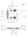
- FIG. 3 shows a top view of the starter battery 1 with the cover 3. It is clear that in the flange 6 a parallel to the narrow Side wall of the starter battery 1 in a longitudinal direction extending slot 13 is provided. Alternatively, the slot but also on the longer side the starter battery 1 may be arranged.
- the formation of the passage opening as a slot 13 has the advantage that the loop of an annularly closed battery box cord slightly from above from the top of the battery cover 3 down in the direction of the battery box. 2 can be plugged without the end of a battery box string consuming by the conventional two spaced through holes must be threaded.
- the battery box cord can be made in one piece in this way be executed, but should have a handle portion 8, which is larger than that Slot 13 is to slippage of the battery box cord through the slot 13 to prevent down.
- the threading of the cord section 9 in the guide opening 14 is through insertion openings 15 allows, as a slot with a longitudinal parallel to the slot 13 seen from the slot 13 in the direction of the associated Langlochendes pointing open insertion side is formed.
- the insertion opening 15 opens into the adjacent guide opening 14 and has a constriction or is formed narrowed in relation to the guide opening 14, so that the cord portion 9 is locked in the guide opening 14, if this is clamped by the insertion opening 15 in the guide opening 14.
- Figures 4a and 4b show two embodiments of the integral with the battery box 2 shaped projection 10 with differently shaped Klemmverriegelungs instituten as partial views as a plan view.
- Figures 4b with parallel to the side wall the battery box 2 extending insertion opening 15, the course of the Insertion opening 15 in the variant of the projection 10, which in the figure 4a is shown, obliquely away from the side wall of the battery box 2 away. This makes possible a lighter mechanical assembly of the battery box cord.
- the assembly of the carrying handle element 7 takes place by detecting the handle portion 8 and sliding down the sagging loop-shaped Cord section through the slot 13. The pushed through the slot 13 Loop of the cord section 9 is then right and left in front of the open insertion of the insertion openings 15 in the projection 10 out. By a short jerk on the handle 8 up the cord section 9 slips up both sides through the insertion opening 15 into the guide openings 14th and becomes due to the narrowing of the insertion opening 15 in the guide opening 14 locked led.
- the assembly of the carrying handle element 7 can be so can be done quickly and easily by hand, but it is also easy to automate.
Landscapes
- Chemical & Material Sciences (AREA)
- Chemical Kinetics & Catalysis (AREA)
- Electrochemistry (AREA)
- General Chemical & Material Sciences (AREA)
- Battery Mounting, Suspending (AREA)
- Dry Shavers And Clippers (AREA)
- Air Bags (AREA)
- Details Of Rigid Or Semi-Rigid Containers (AREA)
- Packages (AREA)
- Supplying Of Containers To The Packaging Station (AREA)
- Toys (AREA)
Description
- Fig. 1 -
- Seitenansicht eines Ausschnitts eines erfindungsgemäßen Batteriekastens;
- Fig. 2a + 2b -
- Ansichten von zwei Ausführungsformen einer Seitenwand des Batteriekastens aus Figur 1;
- Fig. 3 -
- Draufsicht auf den Ausschnitt des Batteriekastens aus Figur 1 mit dem Langloch als Durchführungsöffnung;
- Fig. 4a+4b -
- Ausschnittsansichten als Draufsicht auf den integral mit dem Batteriekasten geformten Vorsprung mit Klemmverriegelungselementen.
Claims (5)
- Batteriekasten (2) mit einer Durchführungsöffnung an einem Flansch (6) des Batteriekastens (2) zur Aufnahme eines Tragegriffelementes (7), das einen länglichen Griffabschnitt (8) hat, der größer als die Durchführungsöffnung ist, und einen an die Enden des Griffabschnitts (8) angebrachten eine Schlaufe bildenden Schnurabschnitt (9) hat, dadurch gekennzeichnet, dass die Durchführungsöffnung ein sich in eine Längsrichtung erstreckendes Langloch (13) ist, durch das die Schlaufe des Schnurabschnitts (9) des Tragegriffelementes (7) durchführbar ist, und an dem Batteriekasten (2) unterhalb der Öffnung des Langlochs (13) im Bereich der Langlochenden jeweils ein Klemmverriegelungselement zur Aufnahme des Schnurabschnitts (9) angeordnet ist, wobei die Klemmverriegelungselemente jeweils eine Einführöffnung (15) haben, die in eine Führungsöffnung (14) für den Schnurabschnitt (9) mündet und gegenüberliegend der Führungsöffnung (14) eine zur Einführung des Schnurabschnitts (9) offene Einführseite und eine Verengung zur verriegelnden Aufnahme des Schnurabschnitts (9) in der angrenzenden Führungsöffnung (14) hat, und wobei die offene Einführseite in Längsrichtung parallel zum Langloch (13) gesehen vom Langloch (13) in Richtung des zugeordneten Langlochendes weist.
- Batteriekasten (2) nach Anspruch 1, dadurch gekennzeichnet, dass die Verengung der Einführöffnung (15) fluchtend mit dem zugeordneten Langlochende ausgerichtet ist.
- Batteriekasten (2) nach Anspruch 1 oder 2, gekennzeichnet durch einen integral mit dem Batteriekasten (2) geformten Vorsprung (10), der sich quer zur Aussenwand des Batteriekastens (2) und parallel in Längsrichtung des Flansches (6) erstreckt, wobei die Klemmverriegelungselemente jeweils in den schmalen an den Batteriekasten (2) angrenzenden Seiten des Vorsprungs (10) geformt sind.
- Batteriekasten (2) nach Anspruch 3, dadurch gekennzeichnet, dass der Vorsprung (10) Verstärkungsrippen (11) quer zur Längsrichtung des Vorsprungs (10) hat, die integral mit dem Vorsprung (10) und dem Batteriekasten (2) verbunden sind.
- Batteriekasten (2) nach Anspruch 3 oder 4, gekennzeichnet durch mindestens eine gegenüberliegend von der Behälterwand an der Unterseite des Vorsprungs (10) angeordnete Nase (12), die in die vom Flansch (6) zum Vorsprung (10) laufende Richtung nach unten weist.
Priority Applications (2)
| Application Number | Priority Date | Filing Date | Title |
|---|---|---|---|
| SI200430004T SI1480283T1 (sl) | 2003-05-21 | 2004-05-19 | Akumulatorski zaboj |
| PL04011897T PL1480283T3 (pl) | 2003-05-21 | 2004-05-19 | Obudowa akumulatora |
Applications Claiming Priority (2)
| Application Number | Priority Date | Filing Date | Title |
|---|---|---|---|
| DE10323024 | 2003-05-21 | ||
| DE10323024A DE10323024B3 (de) | 2003-05-21 | 2003-05-21 | Batteriekasten |
Publications (2)
| Publication Number | Publication Date |
|---|---|
| EP1480283A1 EP1480283A1 (de) | 2004-11-24 |
| EP1480283B1 true EP1480283B1 (de) | 2005-08-24 |
Family
ID=33039251
Family Applications (1)
| Application Number | Title | Priority Date | Filing Date |
|---|---|---|---|
| EP04011897A Expired - Lifetime EP1480283B1 (de) | 2003-05-21 | 2004-05-19 | Batteriekasten |
Country Status (6)
| Country | Link |
|---|---|
| EP (1) | EP1480283B1 (de) |
| AT (1) | ATE302999T1 (de) |
| DE (2) | DE10323024B3 (de) |
| ES (1) | ES2246051T3 (de) |
| PL (1) | PL1480283T3 (de) |
| SI (1) | SI1480283T1 (de) |
Families Citing this family (3)
| Publication number | Priority date | Publication date | Assignee | Title |
|---|---|---|---|---|
| DE102007009770B4 (de) | 2007-02-27 | 2011-05-26 | Vb Autobatterie Gmbh & Co. Kgaa | Bleiakkumulator und Griffanordnung hierfür |
| US8263257B2 (en) * | 2008-06-03 | 2012-09-11 | C&D Technologies, Inc. | Removable handle for industrial battery |
| US12138452B2 (en) | 2018-10-21 | 2024-11-12 | Gerdcare Medical Ltd. | Non-invasive device and method for treating the digestive system and for synchronizing stimulation with breath |
Family Cites Families (8)
| Publication number | Priority date | Publication date | Assignee | Title |
|---|---|---|---|---|
| DE7135447U (de) * | 1972-02-03 | Varta Ag | Battenegefäß fur Starter battenen | |
| DE7538942U (de) * | 1975-12-06 | 1977-05-18 | Varta Batterie Ag, 3000 Hannover | Akkumulatorgehaeuse mit angeformter griffleiste |
| DE2950629C2 (de) * | 1979-12-15 | 1982-05-19 | Fels, Karl, 3387 Vienenburg | Griffschnur für einen Batteriekasten |
| DE3343503C1 (de) * | 1983-12-01 | 1985-07-25 | Fels, Karl, 3387 Vienenburg | Griffschnur für einen Batteriekasten |
| ES279707Y (es) * | 1984-06-05 | 1985-06-01 | Sociedad Espanola Del Acumulador Tudor S.A. | Asa para baterias electricas. |
| DE3533580A1 (de) * | 1985-09-20 | 1987-04-02 | Varta Batterie | Tragevorrichtung fuer einen akkumulator |
| DE8805405U1 (de) * | 1988-04-23 | 1988-07-07 | Fels, Karl, 3380 Goslar | Griff für Batteriekästen |
| US6428927B2 (en) * | 1999-12-02 | 2002-08-06 | Gnb Technologies, Inc. | Detachable rope handle assembly for a battery |
-
2003
- 2003-05-21 DE DE10323024A patent/DE10323024B3/de not_active Expired - Fee Related
-
2004
- 2004-05-19 ES ES04011897T patent/ES2246051T3/es not_active Expired - Lifetime
- 2004-05-19 EP EP04011897A patent/EP1480283B1/de not_active Expired - Lifetime
- 2004-05-19 DE DE502004000049T patent/DE502004000049D1/de not_active Expired - Lifetime
- 2004-05-19 PL PL04011897T patent/PL1480283T3/pl unknown
- 2004-05-19 AT AT04011897T patent/ATE302999T1/de active
- 2004-05-19 SI SI200430004T patent/SI1480283T1/sl unknown
Also Published As
| Publication number | Publication date |
|---|---|
| ES2246051T3 (es) | 2006-02-01 |
| ATE302999T1 (de) | 2005-09-15 |
| EP1480283A1 (de) | 2004-11-24 |
| DE10323024B3 (de) | 2004-12-16 |
| PL1480283T3 (pl) | 2006-01-31 |
| DE502004000049D1 (de) | 2005-09-29 |
| SI1480283T1 (sl) | 2005-12-31 |
Similar Documents
| Publication | Publication Date | Title |
|---|---|---|
| DE3503293A1 (de) | Befestigungsteil | |
| DE3637738C2 (de) | ||
| DE102008032247A1 (de) | Befestigungseinrichtung | |
| EP1533244B1 (de) | Behälter mit schwenkbar angelenktem Deckel | |
| EP1490618B1 (de) | Leitungshalter | |
| EP1596015A1 (de) | Vorrichtung für das Anheben von Betonteilen | |
| DE2614126A1 (de) | Einteiliges sicherheitssiegel und versiegelungssystem | |
| DE102008040136A1 (de) | Transport- und Lagerbehälter aus Kunststoff mit Schiebeelement | |
| EP1480283B1 (de) | Batteriekasten | |
| DE202010005089U1 (de) | Sterilcontainer für medizinische Zwecke | |
| EP2127002B1 (de) | Bleiakkumulator und griffanordnung hierfür | |
| DE4026157A1 (de) | Befestigungsvorrichtung | |
| EP3754845B1 (de) | Vorrichtung zum absorbieren des elektrischen rauschens | |
| DE102018001937A1 (de) | Transportbehälter mit aufsteckbarem Oberrand | |
| DE102018003688B4 (de) | Vorrichtung zur Aufnahme eines Kabelstrangs und System mit einer solchen Vorrichtung | |
| DE102010032176A1 (de) | Steckverbinderhalterung | |
| EP0355854A1 (de) | Trageschnur mit Traggriff | |
| DE3011598C2 (de) | Rohrschelle | |
| DE1684247A1 (de) | Einlageelement und Herstellungsverfahren zur Bildung einer Zugriffsausnehmung | |
| DE29701879U1 (de) | Befestigungsvorrichtung für Stabmatten | |
| DE102018101675A1 (de) | Kraftfahrzeugschließsystem mit verliersicher montierter Feder | |
| DE102007036766A1 (de) | Rollladen insbesondere zur Montage an einer Gebäudeöffnung | |
| DE602004012265T2 (de) | Markisenkasten- und Ausfallprofileinheit | |
| DE202014103118U1 (de) | Gurtspanner | |
| EP2382363A1 (de) | Vorrichtung zur halterung von seilschlaufen |
Legal Events
| Date | Code | Title | Description |
|---|---|---|---|
| PUAI | Public reference made under article 153(3) epc to a published international application that has entered the european phase |
Free format text: ORIGINAL CODE: 0009012 |
|
| 17P | Request for examination filed |
Effective date: 20040914 |
|
| AK | Designated contracting states |
Kind code of ref document: A1 Designated state(s): AT BE BG CH CY CZ DE DK EE ES FI FR GB GR HU IE IT LI LU MC NL PL PT RO SE SI SK TR |
|
| AX | Request for extension of the european patent |
Extension state: AL HR LT LV MK |
|
| GRAP | Despatch of communication of intention to grant a patent |
Free format text: ORIGINAL CODE: EPIDOSNIGR1 |
|
| GRAS | Grant fee paid |
Free format text: ORIGINAL CODE: EPIDOSNIGR3 |
|
| GRAA | (expected) grant |
Free format text: ORIGINAL CODE: 0009210 |
|
| RAP1 | Party data changed (applicant data changed or rights of an application transferred) |
Owner name: VB AUTOBATTERIE GMBH & CO. KGAA |
|
| AKX | Designation fees paid |
Designated state(s): AT BE BG CH CY CZ DE DK EE ES FI FR GB GR HU IE IT LI LU MC NL PL PT RO SE SI SK TR |
|
| AK | Designated contracting states |
Kind code of ref document: B1 Designated state(s): AT BE BG CH CY CZ DE DK EE ES FI FR GB GR HU IE IT LI LU MC NL PL PT RO SE SI SK TR |
|
| PG25 | Lapsed in a contracting state [announced via postgrant information from national office to epo] |
Ref country code: RO Free format text: LAPSE BECAUSE OF FAILURE TO SUBMIT A TRANSLATION OF THE DESCRIPTION OR TO PAY THE FEE WITHIN THE PRESCRIBED TIME-LIMIT Effective date: 20050824 Ref country code: IE Free format text: LAPSE BECAUSE OF FAILURE TO SUBMIT A TRANSLATION OF THE DESCRIPTION OR TO PAY THE FEE WITHIN THE PRESCRIBED TIME-LIMIT Effective date: 20050824 Ref country code: NL Free format text: LAPSE BECAUSE OF FAILURE TO SUBMIT A TRANSLATION OF THE DESCRIPTION OR TO PAY THE FEE WITHIN THE PRESCRIBED TIME-LIMIT Effective date: 20050824 Ref country code: FI Free format text: LAPSE BECAUSE OF FAILURE TO SUBMIT A TRANSLATION OF THE DESCRIPTION OR TO PAY THE FEE WITHIN THE PRESCRIBED TIME-LIMIT Effective date: 20050824 |
|
| REG | Reference to a national code |
Ref country code: GB Ref legal event code: FG4D Free format text: NOT ENGLISH |
|
| REG | Reference to a national code |
Ref country code: CH Ref legal event code: EP |
|
| GBT | Gb: translation of ep patent filed (gb section 77(6)(a)/1977) |
Effective date: 20050824 |
|
| REG | Reference to a national code |
Ref country code: IE Ref legal event code: FG4D Free format text: LANGUAGE OF EP DOCUMENT: GERMAN |
|
| REF | Corresponds to: |
Ref document number: 502004000049 Country of ref document: DE Date of ref document: 20050929 Kind code of ref document: P |
|
| PG25 | Lapsed in a contracting state [announced via postgrant information from national office to epo] |
Ref country code: DK Free format text: LAPSE BECAUSE OF FAILURE TO SUBMIT A TRANSLATION OF THE DESCRIPTION OR TO PAY THE FEE WITHIN THE PRESCRIBED TIME-LIMIT Effective date: 20051124 Ref country code: SE Free format text: LAPSE BECAUSE OF FAILURE TO SUBMIT A TRANSLATION OF THE DESCRIPTION OR TO PAY THE FEE WITHIN THE PRESCRIBED TIME-LIMIT Effective date: 20051124 Ref country code: GR Free format text: LAPSE BECAUSE OF FAILURE TO SUBMIT A TRANSLATION OF THE DESCRIPTION OR TO PAY THE FEE WITHIN THE PRESCRIBED TIME-LIMIT Effective date: 20051124 |
|
| PG25 | Lapsed in a contracting state [announced via postgrant information from national office to epo] |
Ref country code: PT Free format text: LAPSE BECAUSE OF FAILURE TO SUBMIT A TRANSLATION OF THE DESCRIPTION OR TO PAY THE FEE WITHIN THE PRESCRIBED TIME-LIMIT Effective date: 20060124 |
|
| REG | Reference to a national code |
Ref country code: HU Ref legal event code: AG4A Ref document number: E000140 Country of ref document: HU |
|
| NLV1 | Nl: lapsed or annulled due to failure to fulfill the requirements of art. 29p and 29m of the patents act | ||
| REG | Reference to a national code |
Ref country code: ES Ref legal event code: FG2A Ref document number: 2246051 Country of ref document: ES Kind code of ref document: T3 |
|
| REG | Reference to a national code |
Ref country code: IE Ref legal event code: FD4D |
|
| ET | Fr: translation filed | ||
| REG | Reference to a national code |
Ref country code: FR Ref legal event code: CJ Ref country code: FR Ref legal event code: CD |
|
| PG25 | Lapsed in a contracting state [announced via postgrant information from national office to epo] |
Ref country code: BE Free format text: LAPSE BECAUSE OF NON-PAYMENT OF DUE FEES Effective date: 20060531 Ref country code: MC Free format text: LAPSE BECAUSE OF NON-PAYMENT OF DUE FEES Effective date: 20060531 |
|
| PLBE | No opposition filed within time limit |
Free format text: ORIGINAL CODE: 0009261 |
|
| STAA | Information on the status of an ep patent application or granted ep patent |
Free format text: STATUS: NO OPPOSITION FILED WITHIN TIME LIMIT |
|
| 26N | No opposition filed |
Effective date: 20060526 |
|
| BERE | Be: lapsed |
Owner name: VB AUTOBATTERIE G.M.B.H. & CO. KGAA Effective date: 20060531 |
|
| PG25 | Lapsed in a contracting state [announced via postgrant information from national office to epo] |
Ref country code: EE Free format text: LAPSE BECAUSE OF FAILURE TO SUBMIT A TRANSLATION OF THE DESCRIPTION OR TO PAY THE FEE WITHIN THE PRESCRIBED TIME-LIMIT Effective date: 20050824 |
|
| PGFP | Annual fee paid to national office [announced via postgrant information from national office to epo] |
Ref country code: CZ Payment date: 20080521 Year of fee payment: 5 Ref country code: ES Payment date: 20080523 Year of fee payment: 5 Ref country code: HU Payment date: 20080523 Year of fee payment: 5 |
|
| PGFP | Annual fee paid to national office [announced via postgrant information from national office to epo] |
Ref country code: SK Payment date: 20080515 Year of fee payment: 5 |
|
| PGFP | Annual fee paid to national office [announced via postgrant information from national office to epo] |
Ref country code: BG Payment date: 20080521 Year of fee payment: 5 Ref country code: PL Payment date: 20080507 Year of fee payment: 5 Ref country code: SI Payment date: 20080509 Year of fee payment: 5 |
|
| PG25 | Lapsed in a contracting state [announced via postgrant information from national office to epo] |
Ref country code: CY Free format text: LAPSE BECAUSE OF FAILURE TO SUBMIT A TRANSLATION OF THE DESCRIPTION OR TO PAY THE FEE WITHIN THE PRESCRIBED TIME-LIMIT Effective date: 20050824 |
|
| PGFP | Annual fee paid to national office [announced via postgrant information from national office to epo] |
Ref country code: GB Payment date: 20080522 Year of fee payment: 5 |
|
| REG | Reference to a national code |
Ref country code: CH Ref legal event code: PL |
|
| PG25 | Lapsed in a contracting state [announced via postgrant information from national office to epo] |
Ref country code: LI Free format text: LAPSE BECAUSE OF NON-PAYMENT OF DUE FEES Effective date: 20080531 Ref country code: CH Free format text: LAPSE BECAUSE OF NON-PAYMENT OF DUE FEES Effective date: 20080531 |
|
| GBPC | Gb: european patent ceased through non-payment of renewal fee |
Effective date: 20090519 |
|
| PG25 | Lapsed in a contracting state [announced via postgrant information from national office to epo] |
Ref country code: HU Free format text: LAPSE BECAUSE OF NON-PAYMENT OF DUE FEES Effective date: 20090520 Ref country code: CZ Free format text: LAPSE BECAUSE OF NON-PAYMENT OF DUE FEES Effective date: 20090519 |
|
| REG | Reference to a national code |
Ref country code: SK Ref legal event code: MM4A Ref document number: E 464 Country of ref document: SK Effective date: 20090519 |
|
| PG25 | Lapsed in a contracting state [announced via postgrant information from national office to epo] |
Ref country code: SK Free format text: LAPSE BECAUSE OF NON-PAYMENT OF DUE FEES Effective date: 20090519 |
|
| REG | Reference to a national code |
Ref country code: SI Ref legal event code: KO00 Effective date: 20100115 |
|
| PG25 | Lapsed in a contracting state [announced via postgrant information from national office to epo] |
Ref country code: GB Free format text: LAPSE BECAUSE OF NON-PAYMENT OF DUE FEES Effective date: 20090519 Ref country code: SI Free format text: LAPSE BECAUSE OF NON-PAYMENT OF DUE FEES Effective date: 20090520 |
|
| REG | Reference to a national code |
Ref country code: ES Ref legal event code: FD2A Effective date: 20090520 |
|
| REG | Reference to a national code |
Ref country code: PL Ref legal event code: LAPE |
|
| PG25 | Lapsed in a contracting state [announced via postgrant information from national office to epo] |
Ref country code: PL Free format text: LAPSE BECAUSE OF NON-PAYMENT OF DUE FEES Effective date: 20090519 |
|
| PG25 | Lapsed in a contracting state [announced via postgrant information from national office to epo] |
Ref country code: ES Free format text: LAPSE BECAUSE OF NON-PAYMENT OF DUE FEES Effective date: 20090520 |
|
| PG25 | Lapsed in a contracting state [announced via postgrant information from national office to epo] |
Ref country code: BG Free format text: LAPSE BECAUSE OF FAILURE TO SUBMIT A TRANSLATION OF THE DESCRIPTION OR TO PAY THE FEE WITHIN THE PRESCRIBED TIME-LIMIT Effective date: 20090531 |
|
| REG | Reference to a national code |
Ref country code: DE Ref legal event code: R082 Ref document number: 502004000049 Country of ref document: DE Representative=s name: MEISSNER, BOLTE & PARTNER GBR, DE Ref country code: DE Ref legal event code: R082 Ref document number: 502004000049 Country of ref document: DE Representative=s name: MEISSNER BOLTE PATENTANWAELTE RECHTSANWAELTE P, DE |
|
| REG | Reference to a national code |
Ref country code: FR Ref legal event code: PLFP Year of fee payment: 13 |
|
| REG | Reference to a national code |
Ref country code: FR Ref legal event code: PLFP Year of fee payment: 14 |
|
| REG | Reference to a national code |
Ref country code: FR Ref legal event code: PLFP Year of fee payment: 15 |
|
| REG | Reference to a national code |
Ref country code: DE Ref legal event code: R082 Ref document number: 502004000049 Country of ref document: DE Representative=s name: MEISSNER BOLTE PATENTANWAELTE RECHTSANWAELTE P, DE |
|
| REG | Reference to a national code |
Ref country code: LU Ref legal event code: HC Owner name: JOHNSON CONTROLS AUTOBATTERIE GMBH & CO. KGAA; DE Free format text: FORMER OWNER: VB AUTOBATTERIE GMBH & CO. KGAA Effective date: 20200814 Ref country code: LU Ref legal event code: HC Owner name: CLARIOS GERMANY GMBH & CO. KGAA; DE Free format text: FORMER OWNER: JOHNSON CONTROLS AUTOBATTERIE GMBH & CO. KGAA Effective date: 20200814 |
|
| REG | Reference to a national code |
Ref country code: DE Ref legal event code: R079 Ref document number: 502004000049 Country of ref document: DE Free format text: PREVIOUS MAIN CLASS: H01M0002100000 Ipc: H01M0050200000 |
|
| REG | Reference to a national code |
Ref country code: DE Ref legal event code: R082 Ref document number: 502004000049 Country of ref document: DE Representative=s name: MEISSNER BOLTE PATENTANWAELTE RECHTSANWAELTE P, DE Ref country code: DE Ref legal event code: R081 Ref document number: 502004000049 Country of ref document: DE Owner name: CLARIOS GERMANY GMBH & CO. KGAA, DE Free format text: FORMER OWNER: VB AUTOBATTERIE GMBH & CO. KGAA, 30419 HANNOVER, DE |
|
| REG | Reference to a national code |
Ref country code: AT Ref legal event code: HC Ref document number: 302999 Country of ref document: AT Kind code of ref document: T Owner name: CLARIOS GERMANY GMBH & CO. KGAA, DE Effective date: 20210222 |
|
| PGFP | Annual fee paid to national office [announced via postgrant information from national office to epo] |
Ref country code: LU Payment date: 20220527 Year of fee payment: 19 Ref country code: IT Payment date: 20220523 Year of fee payment: 19 Ref country code: FR Payment date: 20220525 Year of fee payment: 19 Ref country code: DE Payment date: 20220527 Year of fee payment: 19 |
|
| PGFP | Annual fee paid to national office [announced via postgrant information from national office to epo] |
Ref country code: TR Payment date: 20220511 Year of fee payment: 19 Ref country code: AT Payment date: 20220504 Year of fee payment: 19 |
|
| REG | Reference to a national code |
Ref country code: DE Ref legal event code: R119 Ref document number: 502004000049 Country of ref document: DE |
|
| REG | Reference to a national code |
Ref country code: AT Ref legal event code: MM01 Ref document number: 302999 Country of ref document: AT Kind code of ref document: T Effective date: 20230519 |
|
| PG25 | Lapsed in a contracting state [announced via postgrant information from national office to epo] |
Ref country code: LU Free format text: LAPSE BECAUSE OF NON-PAYMENT OF DUE FEES Effective date: 20230519 Ref country code: AT Free format text: LAPSE BECAUSE OF NON-PAYMENT OF DUE FEES Effective date: 20230519 |
|
| PG25 | Lapsed in a contracting state [announced via postgrant information from national office to epo] |
Ref country code: IT Free format text: LAPSE BECAUSE OF NON-PAYMENT OF DUE FEES Effective date: 20230519 Ref country code: DE Free format text: LAPSE BECAUSE OF NON-PAYMENT OF DUE FEES Effective date: 20231201 |
|
| PG25 | Lapsed in a contracting state [announced via postgrant information from national office to epo] |
Ref country code: FR Free format text: LAPSE BECAUSE OF NON-PAYMENT OF DUE FEES Effective date: 20230531 |