EP1479803A2 - Verfahren zum Erzeugen einer Musterkette und Musterkettenschärmaschine - Google Patents
Verfahren zum Erzeugen einer Musterkette und Musterkettenschärmaschine Download PDFInfo
- Publication number
- EP1479803A2 EP1479803A2 EP04007004A EP04007004A EP1479803A2 EP 1479803 A2 EP1479803 A2 EP 1479803A2 EP 04007004 A EP04007004 A EP 04007004A EP 04007004 A EP04007004 A EP 04007004A EP 1479803 A2 EP1479803 A2 EP 1479803A2
- Authority
- EP
- European Patent Office
- Prior art keywords
- thread guide
- guide device
- warping drum
- moved
- thread
- Prior art date
- Legal status (The legal status is an assumption and is not a legal conclusion. Google has not performed a legal analysis and makes no representation as to the accuracy of the status listed.)
- Granted
Links
Images


Classifications
-
- D—TEXTILES; PAPER
- D02—YARNS; MECHANICAL FINISHING OF YARNS OR ROPES; WARPING OR BEAMING
- D02H—WARPING, BEAMING OR LEASING
- D02H3/00—Warping machines
- D02H3/04—Sample warpers
Definitions
- the invention relates to a method for generating a Sample chain, in which at least one thread with the help of a Thread guide device around the circumference of a warping drum is led and creates a group of turns, wherein the thread guide device on a control signal out at least once per turn group at a predetermined Angular position axially relative to the warping drum is moved.
- the invention further relates to a pattern warping machine with a warping drum, one Control device, at least one thread guide device, with the help of a rotary drive around the circumference the warping drum movable and with the help of a Axial drive depending on a signal from the Control device axially movable relative to the warping drum and an angular position detection device, which is connected to the control device.
- the threads that later form the pattern chain around the circumference of the warping drum led around.
- One way is pass each thread individually around the warping drum.
- Another option is to use multiple threads to guide around the warping drum at the same time, whereby these threads are then withdrawn from a rotary gate.
- To achieve the required length of the sample chain need the threads with a larger number of turns around the warping drum. If the Warping drum, for example, a circumferential length of 7 m and you need a length of the sample chain of 700 m, then 100 turns per thread are required.
- the thread guide device for the next turn group jump back to the base of the cone, so that the first turn of the new turn group again placed on the circumference of the warping drum becomes.
- the thread guide device must be in relative a relatively long distance in the axial direction return.
- the invention has for its object a sample chain generate with higher working speed can.
- This task is carried out in a method of the type mentioned at the beginning Art solved in that a distance between the angular position and a position at which the Control signal is generated depending on the speed selects with which the thread guide device is moved around the warping drum.
- the distance is preferably chosen so that a movement time, which the thread guide device to overcome of distance, regardless of speed is constant. It doesn't have to be one Act constancy in the mathematical sense. If the response time, the time between the triggering of the Control signal and the start of movement of the thread guide device, and the rotational speed of the thread guide device are known, then one can these two quantities by simply dividing the angular distance determine and thus determine the angular position, at which the control signal must be generated so that the thread guide device at the angular position sets in motion that is desired.
- the thread guide device is preferably also driven a stepper motor.
- a stepper motor allows one high accuracy in the control of the axial position the thread guide device.
- the one with a stepper motor existing inertia with which the stepper motor on the Occurrence of a control signal can respond through the "Early ignition" described above can be compensated.
- one pivots to move the thread guide device a lever around an axis that is parallel to the radial direction of the warping drum.
- the Stepper motor can therefore be designed as a rotary motor be what simplifies its construction and the cost keeps low.
- the thread guide device is then, for example arranged at the tip of the lever. If one now pivots the lever about an axis that is parallel to the radial direction of the warping drum, then there is a corresponding axial movement of the thread guide device. You can also use the Swivel angle of the lever when the control signal is triggered consider. With the axial movement of the Thread guide device is also a shift the thread guide device, for example the the above-mentioned eyelet in a peripheral device.
- the thread guide device is preferably at least a turn towards at least once a first end of the warping drum from the winding group moved out and at least one turn at least once towards a second end of the Warping drum moved out of the winding group. If the accuracy in controlling the axial movement the thread guide device enlarged, then yield yourself additional options to the thread guide device to move. In addition to the return movement the thread guide device that is required to a thread from the radially outer end of the cone to the radial to move back the inner beginning of the cone yourself additional movement options. For example one can move axially opposite in two Directions at the beginning and end of the pattern chain threading the corresponding thread into partial rods facilitate. The partial rods have safety gear whose working speed is limited. Due to the additional possibility of movement of the thread guide device one is no longer necessarily on the Performance of safety gear instructed.
- the thread guide device when moving towards the first end of the Warping drum in front of a safety gear on a partial bar and moving towards the second End led behind a safety gear to a partial rod will and related to the fishing gear operated with the movements of the thread guide device.
- the movements of the thread guide device can now work much faster achieve than was previously possible. Since you also the movements of the thread guide device depending on the working speed the pattern warping machine, i.e. the rotational speed of thread guide devices, is initiated one also makes sure that one catches the appropriate Always hits partial bars correctly.
- the thread guide device with at least one movement from the winding group is moved out into a fixed end position. This simplifies it the movement control for the thread guide device.
- the task is with a sample warping machine of the type mentioned in that the Control device a speed determination device for the circular movement of the thread guide device has that with a signal triggering device is connected, wherein the signal triggering device Has delay element with a variable delay.
- the control signal to trigger the axial movement of the thread guide device to generate time so that taking into account the "inertia" of the axial drive the movement the thread guide device in a predetermined Angular position begins.
- the delay device calculates the trigger angle at which the control signal for the movement of the thread guide device are triggered should, depending on a starting angle, for example a zero crossing. Dependent on from the rotational speed of the thread guide device this trigger angle can now be varied. It so there is a variable delay related to the starting value.
- the speed detection device is preferably connected to the angle detection device and has a differentiation device. Because the angular position the thread guide device running anyway is detected, for example via an angle encoder, there is basically also information about the speed to disposal. The speed of circulation leaves yourself relatively easily by differentiating the Determine the angular position over time.
- the thread guide device preferably has one Stepper motor as an axial drive. With help of a Stepper motor can be the axial position of the thread guide device set relatively precisely.
- the stepper motor as a rotary motor is formed, the axis of rotation of which is parallel is arranged to the radial direction of the warping drum.
- a rotary stepper motor is easy to control. He is relatively inexpensive.
- Is preferably between the rotary drive and the axial drive has a switchable electronic gear arranged.
- This electronic gear can for example realized by the control device his.
- the control device controls, for example the stepper motor so that it per angular increment the thread guide device in the circumferential direction moved, performs a predetermined number of steps. If the rotational speed of the thread guide device is bigger then these steps can be done in a shorter time than one lower orbital speed.
- the thread guide device is preferably in one Helix can be moved around the circumference of the warping drum and the thread guide device is over the beginning and the end of the helix can be moved out. This gives the above in connection with the procedure described advantages.
- partial bars parallel to the axis the warping drum are arranged, each one Catching device on its facing the thread guide device Have end, the thread guide device in front of the safety gear one to the front of the Warping drum protruding part and behind the Catching device from the front of the warping drum reset partial bar is movable.
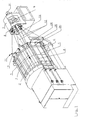
- a sample warping machine shown in Fig. 1 has a warping drum 1 as a winding body on the circumference of axially parachute conveyor belts 2 are arranged, which moves in the direction of an arrow 3 can be.
- the transport belts 3 form a transport surface arrangement.
- Parallel to the axis of the warping drum 1 are partial rods 4, 5, 6 arranged depending on their function also known as cross or cutting bars can be.
- Partial bars On the invisible opposite lying side of the warping drum 1 can more Partial bars may be arranged.
- a rotary gate 7 has a rotor 8, the one Carries a plurality of coils 9 and by a motor 10 is driven.
- the thread guide 11 have eyelets 13 as thread guide devices, through which the threads 12 are guided. These eyelets 13 are arranged at the front end of a lever 14 (Fig. 2 and 3), the one with the help of a servo motor 15 radial arm 16 is rotatable.
- the engine 15 is over a control device 17 controlled so that the eyelet 13th change their position in the direction of a double arrow 18 can.
- the arms 16 are driven by the rotor 7 via a shaft 19, i.e. the thread guides 11 rotate synchronously the rotor 7.
- a thread thickness measuring device 20 is in the movement path the threads 12 arranged.
- the thread thickness measuring device has a measuring field 21 through which the thread 12 a circular path is led. He shadows you Sensor 22 depending on its thickness.
- the Thread thickness measuring device 20 thus determines each Thread 12 once per revolution (direction 23) the thickness and reports the thickness to the control device 17.
- Sorting fingers 24, 25, 26 are on the partial bars 4, 5, 6 arranged at the end that the rotary gate 7th is facing.
- the sorting fingers 24 - 26 serve to Thread so that they are either radially outside of the partial rods 4, 5, 6 or radially within the partial rods 4, 5, 6 come to rest, each based on the Warping drum 1.
- Using the sorting fingers 24, 25, 26 it is possible to form crosses. Crosses are needed usually at the beginning and end of a chain to one hand to separate the threads and on the other hand the To be able to cut threads.
- Fig. 1 there are three partial bars shown. However, more partial bars can also be used be present, for example four, as shown in FIG. 4 is shown.
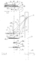
- Fig. 4 now shows a schematic side view of the Warping machine.
- the same elements as in Fig. 1 are with provided with the same reference numerals.
- four sub-bars, 4a, 4b, 5a, 5b which form of crosses at the beginning and end of the chain.
- Each sub-bar 4a, 4b or 5a, 5b is with a sorting finger 24a, 24b or 25a, 25b provided, as shown for the sorting finger 24a is pivotable in the direction of a double arrow 27 is.
- the transport belts 2 are guided around deflection rollers 28. There is already a winding on the transport belt 2 29 formed, i.e. you already have a variety of threads with an appropriate number of turns the warping drum 1 led around.
- the winding 29 in one by one Arrow 30 shown warping direction moved by the Transport belts 2 are driven. This movement can be done during winding, preferably with a constant speed. But it can also take place when a turn group has been completed and a new group of turns is started should.
- the winding 29 is conical Front 31 has. Is shown in dashed lines a boundary 33 between the winding 29 and a winding group 32, which has just been completed.
- a turn group consists of a number of turns of the thread or threads that together the desired Length of the sample chain to be generated.
- the winding group 32 is conical on one side by the End face 31 and on the other side limited by the broken line 33.
- the front threads move (in the warping direction 30 seen) from a lower position 34 into one upper position 35 when the winding group is completed and the back threads move from one lower position 36 to an upper position 37 they are guided by the thread guides 11, more precisely from the eyelet 13 on the arm 14.
- the movement of the threads 12a, 12b during winding is replaced by a corresponding one Swiveling movement of the lever 14 caused by the motor 15 can be controlled.
- the two sub-staff groups are each with two partial bars 4a, 4b and 5a, 5b are provided. If threads lying next to each other are numbered, then Threads G with an even order number above of sub-bar 4a, while all other threads be wound directly into the winding 29. At the other Sub-bar 4b are the threads U with an odd order number filed above the sub-bar 4b and all other threads wound in the winding 29. With the two it is similar to other sub-bars 5a, i.e.
- the lever 14 is also pivoted further, than this for making a winding group is required.
- the Lever 14 pivoted into a position c, that is from a Area out that for winding the winding group is required.
- the eye 13 thus leaves a helical Railway with which they have so far been around Warping drum 1 has been led around.
- arm 14 is moved to a position d moved outside the helix to the rotary gate 7, around the thread 12d to the right of the sorting fingers 25a, 25b past, of course on the sorting finger 25a only threads with even serial number and on the sorting finger 25b only threads with an odd order number to be led past.
- At least the position c of the lever 14 in Fig. 4 can be an end position that the motor 15 can control. This simplifies control. The motor 15 becomes simple to reach this position c, in an end position hazards.
- the eyelets 13 are on a circular path. 40 moves. at at a position 41, for example 200 °, the eyelet 13 can be moved by pivoting the lever 14.
- the motor must be able to carry out this pivoting movement 15, which is designed here as a rotating stepper motor is from a control device 42 with a signal can be controlled.
- the engine 15 has, however a certain sluggishness, i.e. he responds with a short Delay time of 4-6 ms on the signal. In this The eyelet 13 has time depending on the rotational speed of the lever 16 a larger one covered a smaller distance. Would you like this speed would not take into account then the eyelet 13 is already in a position 43 if the movement of the lever 14 begins.
- a rotation angle detection device provided with an encoder 45, which interacts with the arm 16 and a sensor 46, that from the encoder 45 with a predetermined number of pulses is supplied per angular increment.
- the sensor 46 is connected to an angle encoder 47, the one current angle ⁇ of the arm 16 determined.
- a reference angle specification 49 specifies a reference angle ⁇ 0 . This can be, for example, the upper apex of the movement of the arm 16, that is to say the angle at which the arm 16 points vertically upwards. Starting from this reference angle ⁇ 0 , the angular position at which the lever 14 should actually move is determined, for example the 200 ° mentioned above.
- a delay device 50 is now provided which makes the difference between the reference angle ⁇ 0 and the generation of the signal for controlling the motor 15 from the speed ⁇ .
- the delay device 50 is supplied with the speed ⁇ .
- the greater the speed the earlier a signal is generated which drives the motor 15.
- the start of the rotary movement is shifted to a position of 194 °, so that the arm 14 can carry out a rotary movement about its pivot axis at 200 °.
- the control device shown in FIG. 6 can be used 51 can also be used as an "electronic gear".
- the stepper motor 15 moves the lever 14 relatively small increments of angle and swings it around an axis parallel to the radial direction of the warping drum 1 is aligned. You can now use an angular increment that the arm 16 travels as it rotates, a predetermined number of steps of the Assign stepper motor 15. If the arm 16 slower rotates, then stands for this number of steps more time available than if the arm 16 faster rotates.
Landscapes
- Engineering & Computer Science (AREA)
- Textile Engineering (AREA)
- Warping, Beaming, Or Leasing (AREA)
Abstract
Description
- Fig. 1
- eine schematische Gesamtansicht einer Musterkettenschärmaschine mit Drehgatter,
- Fig. 2
- Fadenführer und Drehgatter der Schärmaschine nach Fig.1,
- Fig. 3
- eine Ausführungsform eines Fadenführers,
- Fig. 4
- eine schematische Darstellung zur Erläuterung der Fadenführung,
- Fig. 5
- eine schematische Darstellung zur Erläuterung der Ansteuerung der Fadenführereinrichtung und
- Fig.-6
- eine schematische Darstellung der Steuereinrichtung.
Claims (15)
- Verfahren zum Erzeugen einer Musterkette, bei dem mindestens ein Faden mit Hilfe einer Fadenführereinrichtung um den Umfang einer Schärtrommel geführt wird und eine Windungsgruppe erzeugt, wobei die Fadenführereinrichtung auf ein Steuersignal hin mindestens einmal pro Windungsgruppe an einer vorbestimmten Winkelposition axial relativ zur Schärtrommel bewegt wird, dadurch gekennzeichnet, daß man einen Abstand zwischen der Winkelposition und einer Position, an der das Steuersignal erzeugt wird, in Abhängigkeit von der Geschwindigkeit wählt, mit der die Fadenführereinrichtung um die Schärtrommel herum bewegt wird.
- Verfahren nach Anspruch 1, dadurch gekennzeichnet, daß man den Abstand so wählt, daß eine Bewegungszeit, die die Fadenführereinrichtung zum Überwinden des Abstands benötigt, unabhängig von der Geschwindigkeit konstant ist.
- Verfahren nach Anspruch 1 oder 2, dadurch gekennzeichnet, daß man die Fadenführereinrichtung mit einem Schrittmotor antreibt.
- Verfahren nach einem der Ansprüche 1 bis 3, dadurch gekennzeichnet, daß man zur Bewegung der Fadenführereinrichtung einen Hebel um eine Achse verschwenkt, die parallel zur Radialrichtung der Schärtrommel verläuft.
- Verfahren nach einem der Ansprüche 1 bis 4, dadurch gekennzeichnet, daß die Fadenführereinrichtung bei mindestens einer Windung mindestens einmal in Richtung auf ein erstes Ende der Schärtrommel aus der Windungsgruppe herausbewegt wird und bei mindestens einer Windung mindestens einmal in Richtung auf ein zweites Ende der Schärtrommel aus der Windungsgruppe herausbewegt wird.
- Verfahren nach Anspruch 5, dadurch gekennzeichnet, daß die Fadenführereinrichtung bei der Bewegung in Richtung auf das erste Ende der Schärtrommel vor einer Fangeinrichtung an einen Teilstab und bei der Bewegung in Richtung auf das zweite Ende hinter einer Fangeinrichtung an einem Teilstab geführt wird und man die Fangeinrichtungen im Zusammenhang mit den Bewegungen der Fadenführereinrichtung betätigt.
- Verfahren nach Anspruch 5 oder 6, dadurch gekennzeichnet, daß die Fadenführereinrichtung bei mindestens einer Bewegung aus der Windungsgruppe heraus in eine feste Endposition bewegt wird.
- Verfahren nach einem der Ansprüche 1 bis 7, dadurch gekennzeichnet, daß man eine Bewegungsgeschwindigkeit, mit der die Fadenführereinrichtung axial bewegt wird, an die Geschwindigkeit anpaßt, mit der die Fadenführereinrichtung um den Umfang der Schärtrommel herum bewegt wird.
- Musterkettenschärmaschine mit einer Schärtrommel, einer Steuereinrichtung, mindestens einer Fadenführereinrichtung, die mit Hilfe eines Rotationsantriebs um den Umfang der Schärtrommel bewegbar und mit Hilfe eines Axialantriebs in Abhängigkeit von einem Signal der Steuereinrichtung axial relativ zur Schärtrommel bewegbar ist, und einer Winkelpositionserfassungseinrichtung, die mit der Steuereinrichtung verbunden ist, dadurch gekennzeichnet, daß die Steuereinrichtung (51) eine Geschwindigkeitsermittlungseinrichtung (48) für die Umlaufbewegung der Fadenführereinrichtung (13) aufweist, die mit einer Signalauslöseeinrichtung verbunden ist, wobei die Signalauslöseeinrichtung ein Verzögerungsglied (50) mit einer variablen Verzögerung aufweist.
- Maschine nach Anspruch 9, dadurch gekennzeichnet, daß die Geschwindigkeitsermittlungseinrichtung (48) mit der Winkelerfassungseinrichtung (47) verbunden ist und eine Differenzierungseinrichtung aufweist.
- Maschine nach Anspruch 9 oder 10, dadurch gekennzeichnet, daß die Fadenführereinrichtung (13) einen Schrittmotor (15) als Axialantrieb aufweist.
- Maschine nach Anspruch 11, dadurch gekennzeichnet, daß der Schrittmotor (15) als Rotationsmotor ausgebildet ist, dessen Rotationsachse parallel zur Radialrichtung der Schärtrommel (1) angeordnet ist.
- Maschine nach einem der Ansprüche 9 bis 12, dadurch gekennzeichnet, daß zwischen dem Rotationsantrieb (10) und dem Axialantrieb (15) ein schaltbares elektronisches Getriebe angeordnet ist.
- Maschine nach einem der Ansprüche 9 bis 13, dadurch gekennzeichnet, daß die Fadenführereinrichtung (13) in einer Schraubenlinie um den Umfang der Schärtrommel (1) herum bewegbar ist und die Fadenführereinrichtung (13) über den Anfang und das Ende der Schraubenlinie heraus bewegbar ist.
- Maschine nach einem der Ansprüche 9 bis 14, dadurch gekennzeichnet, daß Teilstäbe (4), (4a), (4b), (5), (5a), (5b), (6) parallel zur Achse der Schärtrommel (1) angeordnet sind, die jeweils eine Fangeinrichtung (24a), (24b), (25a), (25b), (24-26) an ihren der Fadenführereinrichtung (13) zugewandten Ende aufweisen, wobei die Fadenführereinrichtung (13) vor die Fangeinrichtung eines zur Stirnseite der Schärtrommel (1) vorstehenden Teilstabes (5a), (5b) und hinter die Fangeinrichtung (24a), (24b) eines von der Stirnseite der Schärtrommel (1) zurückgesetzten Teilstabes (4a), (4b) bewegbar ist.
Applications Claiming Priority (2)
| Application Number | Priority Date | Filing Date | Title |
|---|---|---|---|
| DE10323352 | 2003-05-23 | ||
| DE2003123352 DE10323352B4 (de) | 2003-05-23 | 2003-05-23 | Verfahren zum Erzeugen einer Musterkette und Musterkettenschärmaschine |
Publications (3)
| Publication Number | Publication Date |
|---|---|
| EP1479803A2 true EP1479803A2 (de) | 2004-11-24 |
| EP1479803A3 EP1479803A3 (de) | 2005-04-20 |
| EP1479803B1 EP1479803B1 (de) | 2008-09-17 |
Family
ID=33039295
Family Applications (1)
| Application Number | Title | Priority Date | Filing Date |
|---|---|---|---|
| EP20040007004 Expired - Lifetime EP1479803B1 (de) | 2003-05-23 | 2004-03-24 | Verfahren zum Erzeugen einer Musterkette und Musterkettenschärmaschine |
Country Status (4)
| Country | Link |
|---|---|
| EP (1) | EP1479803B1 (de) |
| JP (1) | JP4643928B2 (de) |
| DE (2) | DE10323352B4 (de) |
| ES (1) | ES2311765T3 (de) |
Cited By (3)
| Publication number | Priority date | Publication date | Assignee | Title |
|---|---|---|---|---|
| EP2239357A1 (de) | 2009-04-08 | 2010-10-13 | Karl Mayer Textilmaschinenfabrik GmbH | Musterkettenschärmaschine |
| EP2239356A1 (de) | 2009-04-08 | 2010-10-13 | Karl Mayer Textilmaschinenfabrik GmbH | Musterkettenschärmaschine und Verfahren zum Betreiben einer Musterkettenschärmaschine |
| CN112663195A (zh) * | 2021-01-08 | 2021-04-16 | 天津工业大学 | 一种穿分绞纱装置 |
Families Citing this family (1)
| Publication number | Priority date | Publication date | Assignee | Title |
|---|---|---|---|---|
| EP3399081B1 (de) * | 2017-05-04 | 2020-04-08 | KARL MAYER R&D GmbH | Musterkettenschärmaschine |
Family Cites Families (6)
| Publication number | Priority date | Publication date | Assignee | Title |
|---|---|---|---|---|
| JPH02169737A (ja) * | 1988-12-22 | 1990-06-29 | Suzuki Waapaa:Kk | 複本数同時整経可能な電子制御サンプル整経機 |
| DE4304956C2 (de) * | 1993-02-18 | 1998-09-24 | Mayer Textilmaschf | Verfahren und Vorrichtung zum Schären von Fäden |
| DE19845244C1 (de) * | 1998-10-01 | 1999-09-23 | Mayer Textilmaschf | Musterketten-Schärmaschine |
| DE19910833C1 (de) * | 1999-03-11 | 2000-05-31 | Mayer Textilmaschf | Kurzketten-Schärmaschine |
| DE10057356B4 (de) * | 2000-11-18 | 2005-11-24 | Karl Mayer Textilmaschinenfabrik Gmbh | Verfahren zum Erzeugen einer Musterkette und Musterketten-Schärmaschine |
| DE10061490C1 (de) * | 2000-12-09 | 2001-11-29 | Mayer Textilmaschf | Verfahren zum Erzeugen einer Musterkette und Musterketten-Schärmaschine |
-
2003
- 2003-05-23 DE DE2003123352 patent/DE10323352B4/de not_active Expired - Fee Related
-
2004
- 2004-03-24 ES ES04007004T patent/ES2311765T3/es not_active Expired - Lifetime
- 2004-03-24 EP EP20040007004 patent/EP1479803B1/de not_active Expired - Lifetime
- 2004-03-24 DE DE200450008070 patent/DE502004008070D1/de not_active Expired - Lifetime
- 2004-05-14 JP JP2004144380A patent/JP4643928B2/ja not_active Expired - Lifetime
Cited By (4)
| Publication number | Priority date | Publication date | Assignee | Title |
|---|---|---|---|---|
| EP2239357A1 (de) | 2009-04-08 | 2010-10-13 | Karl Mayer Textilmaschinenfabrik GmbH | Musterkettenschärmaschine |
| EP2239356A1 (de) | 2009-04-08 | 2010-10-13 | Karl Mayer Textilmaschinenfabrik GmbH | Musterkettenschärmaschine und Verfahren zum Betreiben einer Musterkettenschärmaschine |
| JP2010242275A (ja) * | 2009-04-08 | 2010-10-28 | Karl Mayer Textil Mas Fab Gmbh | 柄経糸用部分整経機及び柄経糸用部分整経機を作動させるための方法 |
| CN112663195A (zh) * | 2021-01-08 | 2021-04-16 | 天津工业大学 | 一种穿分绞纱装置 |
Also Published As
| Publication number | Publication date |
|---|---|
| DE10323352A1 (de) | 2004-12-23 |
| JP4643928B2 (ja) | 2011-03-02 |
| ES2311765T3 (es) | 2009-02-16 |
| DE10323352B4 (de) | 2006-09-14 |
| EP1479803A3 (de) | 2005-04-20 |
| EP1479803B1 (de) | 2008-09-17 |
| JP2004346478A (ja) | 2004-12-09 |
| DE502004008070D1 (de) | 2008-10-30 |
Similar Documents
| Publication | Publication Date | Title |
|---|---|---|
| DE69413315T2 (de) | Verfahren und Vorrichtung zur Fadenverlegung auf einer Spule mit einer genuteten Antriebswalze | |
| DE3307301C2 (de) | ||
| CH662104A5 (de) | Verfahren zum aufwickeln von garn auf einen sich drehenden wickel und vorrichtung zur durchfuehrung des verfahrens. | |
| DE2817711C2 (de) | Vorrichtung zum Steuern des Spulenantriebes einer Flügel-Vorspinnmaschine | |
| DE2129973B2 (de) | Vorrichtung zur Bildung von Fadenreserven bei OHen-End-Splnnmaechinen | |
| CH693380A5 (de) | Verfahren und Vorrichtung zum Aufspulen eines kontinuierlich zulaufenden Fadens. | |
| DE3246381C1 (de) | Vorrichtung zum Herstellen von Maschendrahtgeflecht | |
| DE10323352B4 (de) | Verfahren zum Erzeugen einer Musterkette und Musterkettenschärmaschine | |
| DE3244887C2 (de) | ||
| EP1930489B1 (de) | Musterkettenschärmaschine und Verfahren zum Erzeugen einer Musterkette | |
| DE10323351B4 (de) | Musterkettenschärmaschine | |
| DE19535087A1 (de) | Rundstrickmaschine | |
| EP1445361B1 (de) | Verfahren zum Erzeugen einer Musterkette und Musterkettenschärmaschine | |
| EP1479806B1 (de) | Verfahren zum Erzeugen einer Musterkette und Musterkettenschärmaschine | |
| EP1479804B1 (de) | Verfahren zum Erzeugen einer Musterkette und Musterkettenschärmaschine | |
| DE10057354B4 (de) | Verfahren zum Erzeugen einer Musterkette und Musterketten-Schärmaschine | |
| DE10057356B4 (de) | Verfahren zum Erzeugen einer Musterkette und Musterketten-Schärmaschine | |
| DE2844903C2 (de) | ||
| DE2212935A1 (de) | Kettenwirkmaschine | |
| DE894299C (de) | Rundstrickmaschine | |
| CH654041A5 (de) | Verfahren zur steuerung der abmessung von schussfaeden auf einer schuetzenlosen webmaschine und rotationsfadenabmesser zur durchfuehrung des verfahrens. | |
| DE2608855A1 (de) | Verfahren und vorrichtung zur steuerung des schaerblattes einer kettenschaermaschine | |
| EP2975176B1 (de) | Vorrichtung zum Herstellen von Wendelsieben | |
| DE360755C (de) | Maschine zum Lochen von Jacquardkarten fuer Stickmaschinen | |
| DE2945469A1 (de) | Textiles element fuer eine gelenkscheibe sowie verfahren und vorrichtung zum herstellen eines solchen |
Legal Events
| Date | Code | Title | Description |
|---|---|---|---|
| PUAI | Public reference made under article 153(3) epc to a published international application that has entered the european phase |
Free format text: ORIGINAL CODE: 0009012 |
|
| AK | Designated contracting states |
Kind code of ref document: A2 Designated state(s): AT BE BG CH CY CZ DE DK EE ES FI FR GB GR HU IE IT LI LU MC NL PL PT RO SE SI SK TR |
|
| AX | Request for extension of the european patent |
Extension state: AL LT LV MK |
|
| PUAL | Search report despatched |
Free format text: ORIGINAL CODE: 0009013 |
|
| AK | Designated contracting states |
Kind code of ref document: A3 Designated state(s): AT BE BG CH CY CZ DE DK EE ES FI FR GB GR HU IE IT LI LU MC NL PL PT RO SE SI SK TR |
|
| AX | Request for extension of the european patent |
Extension state: AL LT LV MK |
|
| 17P | Request for examination filed |
Effective date: 20050330 |
|
| AKX | Designation fees paid |
Designated state(s): CH DE ES IT LI |
|
| GRAP | Despatch of communication of intention to grant a patent |
Free format text: ORIGINAL CODE: EPIDOSNIGR1 |
|
| GRAS | Grant fee paid |
Free format text: ORIGINAL CODE: EPIDOSNIGR3 |
|
| GRAA | (expected) grant |
Free format text: ORIGINAL CODE: 0009210 |
|
| AK | Designated contracting states |
Kind code of ref document: B1 Designated state(s): CH DE ES IT LI |
|
| REG | Reference to a national code |
Ref country code: CH Ref legal event code: NV Representative=s name: BOVARD AG PATENTANWAELTE Ref country code: CH Ref legal event code: EP |
|
| REF | Corresponds to: |
Ref document number: 502004008070 Country of ref document: DE Date of ref document: 20081030 Kind code of ref document: P |
|
| REG | Reference to a national code |
Ref country code: ES Ref legal event code: FG2A Ref document number: 2311765 Country of ref document: ES Kind code of ref document: T3 |
|
| PLBE | No opposition filed within time limit |
Free format text: ORIGINAL CODE: 0009261 |
|
| STAA | Information on the status of an ep patent application or granted ep patent |
Free format text: STATUS: NO OPPOSITION FILED WITHIN TIME LIMIT |
|
| 26N | No opposition filed |
Effective date: 20090618 |
|
| PGFP | Annual fee paid to national office [announced via postgrant information from national office to epo] |
Ref country code: CH Payment date: 20100325 Year of fee payment: 7 Ref country code: ES Payment date: 20100324 Year of fee payment: 7 |
|
| REG | Reference to a national code |
Ref country code: CH Ref legal event code: PFA Owner name: KARL MAYER TEXTILMASCHINENFABRIK GMBH Free format text: KARL MAYER TEXTILMASCHINENFABRIK GMBH#BRUEHLSTRASSE 25#63179 OBERTSHAUSEN (DE) -TRANSFER TO- KARL MAYER TEXTILMASCHINENFABRIK GMBH#BRUEHLSTRASSE 25#63179 OBERTSHAUSEN (DE) |
|
| REG | Reference to a national code |
Ref country code: CH Ref legal event code: PL |
|
| PG25 | Lapsed in a contracting state [announced via postgrant information from national office to epo] |
Ref country code: CH Free format text: LAPSE BECAUSE OF NON-PAYMENT OF DUE FEES Effective date: 20110331 Ref country code: LI Free format text: LAPSE BECAUSE OF NON-PAYMENT OF DUE FEES Effective date: 20110331 |
|
| REG | Reference to a national code |
Ref country code: ES Ref legal event code: FD2A Effective date: 20120424 |
|
| PG25 | Lapsed in a contracting state [announced via postgrant information from national office to epo] |
Ref country code: ES Free format text: LAPSE BECAUSE OF NON-PAYMENT OF DUE FEES Effective date: 20110325 |
|
| REG | Reference to a national code |
Ref country code: DE Ref legal event code: R082 Ref document number: 502004008070 Country of ref document: DE Representative=s name: KEIL & SCHAAFHAUSEN PATENT- UND RECHTSANWAELTE, DE Ref country code: DE Ref legal event code: R082 Ref document number: 502004008070 Country of ref document: DE |
|
| REG | Reference to a national code |
Ref country code: DE Ref legal event code: R082 Ref document number: 502004008070 Country of ref document: DE Ref country code: DE Ref legal event code: R081 Ref document number: 502004008070 Country of ref document: DE Owner name: KARL MAYER R&D GMBH, DE Free format text: FORMER OWNER: KARL MAYER TEXTILMASCHINENFABRIK GMBH, 63179 OBERTSHAUSEN, DE Ref country code: DE Ref legal event code: R081 Ref document number: 502004008070 Country of ref document: DE Owner name: KARL MAYER STOLL R&D GMBH, DE Free format text: FORMER OWNER: KARL MAYER TEXTILMASCHINENFABRIK GMBH, 63179 OBERTSHAUSEN, DE |
|
| PGFP | Annual fee paid to national office [announced via postgrant information from national office to epo] |
Ref country code: IT Payment date: 20230321 Year of fee payment: 20 Ref country code: DE Payment date: 20230328 Year of fee payment: 20 |
|
| P01 | Opt-out of the competence of the unified patent court (upc) registered |
Effective date: 20230705 |
|
| REG | Reference to a national code |
Ref country code: DE Ref legal event code: R071 Ref document number: 502004008070 Country of ref document: DE |