EP1477745A2 - Lüftungsvorrichtung mit Schall reduzierender Kapselung - Google Patents
Lüftungsvorrichtung mit Schall reduzierender Kapselung Download PDFInfo
- Publication number
- EP1477745A2 EP1477745A2 EP04006042A EP04006042A EP1477745A2 EP 1477745 A2 EP1477745 A2 EP 1477745A2 EP 04006042 A EP04006042 A EP 04006042A EP 04006042 A EP04006042 A EP 04006042A EP 1477745 A2 EP1477745 A2 EP 1477745A2
- Authority
- EP
- European Patent Office
- Prior art keywords
- capsule
- ventilation device
- sound
- blower
- filter
- Prior art date
- Legal status (The legal status is an assumption and is not a legal conclusion. Google has not performed a legal analysis and makes no representation as to the accuracy of the status listed.)
- Withdrawn
Links
Images


Classifications
-
- F—MECHANICAL ENGINEERING; LIGHTING; HEATING; WEAPONS; BLASTING
- F24—HEATING; RANGES; VENTILATING
- F24F—AIR-CONDITIONING; AIR-HUMIDIFICATION; VENTILATION; USE OF AIR CURRENTS FOR SCREENING
- F24F13/00—Details common to, or for air-conditioning, air-humidification, ventilation or use of air currents for screening
- F24F13/24—Means for preventing or suppressing noise
-
- F—MECHANICAL ENGINEERING; LIGHTING; HEATING; WEAPONS; BLASTING
- F24—HEATING; RANGES; VENTILATING
- F24F—AIR-CONDITIONING; AIR-HUMIDIFICATION; VENTILATION; USE OF AIR CURRENTS FOR SCREENING
- F24F7/00—Ventilation
- F24F7/04—Ventilation with ducting systems, e.g. by double walls; with natural circulation
- F24F7/06—Ventilation with ducting systems, e.g. by double walls; with natural circulation with forced air circulation, e.g. by fan positioning of a ventilator in or against a conduit
Definitions
- the invention relates to a ventilation device with sound and Acoustic encapsulation, especially for one in buildings with central or decentralized Ventilation provided ventilation device on the building side.
- Ventilation devices used for ventilation of rooms in a building usually include at least one or more fans.
- the blowers at which are radial blowers, axial blowers or tangential blowers can, are usually embedded in made of sheet metal or in die-cast housing. These blower housings are used to reduce the noise level emanating from the blower inserted in foamed damping material. With foamed damping materials a reduction in the noise level emanating from the fan can be achieved, however, the damper materials most commonly used today are acoustic open damping materials.
- the object of the present invention is to overcome the disadvantages of the state of the art Remedy technology and provide a ventilation device that is in terms of this outgoing noise level and its heat loss is optimized.
- the complete proposed according to the invention Encapsulation of a blower, which is accommodated within a ventilation device, the noise level emanating from the ventilation device can be significantly reduced.
- the Encapsulation for the blower which is a radial, an axial as well as a tangential blower can act is achieved by a sound capsule that is in one has a horizontal or vertical plane formed parting line.
- the preferably two-part sound capsule has one in the two along the Parting on adjacent capsule parts formed cavity, which to the Geometry of the fan wheel to be enclosed in a radial, axial or Tangential blower is adjusted.
- the two parts of the sound capsule are designed that on their sides lying along the parting line an acoustic closed system forming, form - fitting elements in the form of ribs and Wells, tongue and groove are executed.
- an acoustic closed system forming, form - fitting elements in the form of ribs and Wells, tongue and groove are executed.
- the sound capsule which is either horizontal or in is formed vertically divided from a foamable damping material are manufactured.
- the sound capsule made of moldable plastic material, such as Example EPP (expanded polypropylene) are manufactured; next to it can materials fire protection classes A1, A2 are used. These materials are in theirs Shape very variable, so that the cavity accommodating the blower is in the both parts of the sound capsule to the respective geometry of the blower used it can adapt a radial, an axial or even a tangential fan. Furthermore this material has very good thermal insulation properties, so that a Encapsulation of the blower and thus a change in temperature emanating from the blower can be excluded within the ventilation device.
- a Radial blower from the divided in horizontal, vertical or diagonal direction Enclosed sound capsule one can on the two parts of the sound capsule Torque support can be provided in the form of a recess for the fan drive.
- the electrical connecting lines for power supply and Voltage monitoring of the electric drive driving the blower from the Bottom or a side surface of the divided in the horizontal or vertical direction Sonic capsule led out.
- split sound capsule in one side the sound capsule or in both parts of the sound capsule each provided a blow-out opening his.
- the ventilation device can pass through the unsuitable outlet duct a suitable sealing plug, which also improves the sealing effect Has tongue / groove or ribs / recess, are sealed, so that no external air is drawn in by the fan enclosed by the sound capsule he follows.
- the sound capsule designed according to the invention also makes it possible to the two blow-out openings provided on the sides of the sound capsule to close a plug element and one separating the two blow-out channels To remove the center bar, so that the air blown out by the blower over this from the the split surrounding sound capsule is able to flow out.
- the variability of the release or closing of different, in the Acoustic capsule designed blowout openings through plug elements can be a very easy adaptation of the sound capsule to the respective application requirements, in particular can be achieved with regard to the ducting in a ventilation unit.
- a filter frame On one side of the sound capsule enclosing the fan, preferably on that Intake opening contained side of the sound capsule of the blower, can be a filter frame be provided.
- the filter frame can either be placed on the intake opening plug on the side of the split sound capsule, or with it Glue the top side.
- the filter frame has an open side and is as Insert filter frame.
- the U-shaped filter frame includes Insertion rails that are between rails formed on the top of the sound capsule are led.
- the insert rails which can be designed as profile rails, have a Guide surface on which the insert filter element to be inserted into the filter frame is drawer-like.
- the connector between the one on the shared Acoustic filter frame can also be inserted through a rib / recess or tongue and groove arrangement, so that the sound capsule enclosed blower only sucks in filtered air passing through the filter element.
- the filter frame can be opened by 90 °, Twisted 180 ° or 270 ° or 360 ° or at any angle at the Suction opening of the blower-side of the split sound capsule mounted become.
- the sealing effect in addition to the improvement of the sealing effect, the guarantee at the parting line the mutually facing end faces of the first sound capsule part and the second Part of the sound capsule, on the one hand, the sealing effect, on the other hand, can be achieved through the design the mutually facing end faces of the sound capsule parts their fixation to each other to reach.
- the sound capsule proposed according to the invention which as an axial, radial and encloses a fan designed as a tangential fan, can be installed on ventilation devices that are used as ceiling fans, floor fans, Parapet ventilators and window ventilators in rooms of buildings with a central one or decentralized ventilation concept.
- the Ventilation device takes next to the fan enclosed by a sound capsule in addition, a heat recovery unit, exhaust air and / or recirculation and Outside air mixing ducts and one or more blowers together with their drives.
- each the blower arranged in the ventilation device is used to reduce the Ventilation device starting total noise level from the invention proposed sound encapsulation.
- the ventilation device can over it with an infinitely variable control of the outside air admixture, regulated fresh air flap be provided with which a suctioned on the room side Airflow on freely selectable, depending on the outside temperature Fresh air volume flow can be added.
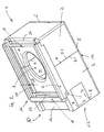
- FIG. 1 is a perspective view of a sound capsule remove which has a butt joint running in the vertical direction.
- a sound capsule 1 comprises a first capsule part 2 and a second capsule part 3 rest with their contact surfaces along a butt joint 4.
- the sound capsule 1 according to the Representation in Figure 1 has a rectangular plan, but could also be square.
- the long side of the split capsule 1 is with Reference numeral 5 marked, while the transverse side of the split sound capsule 1 by Reference numeral 6 is identified.
- the component 1 is referred to as a sound capsule 1, so is that Thermal insulation function of the sound capsule 1 proposed according to the invention always to read with.
- the sound capsule 1 allows the fan to be encapsulated with respect to the Acoustics as well as the shape of an air flow channel within the divided Sound capsule 1 an optimization of the air flow through rounded design of the Flow channels.
- the sound capsule 1 according to the invention offers the possibility of a thermal separation of the air flows from each other.
- On a contact surface 2.1 of the first Capsule part 2 is formed a recess 8, while this on an opposite Contact surface 3.1 of the second capsule part 3 has a raised projecting rib 7 is.
- the recess 8 and the rib 7 engage according to the tongue and groove principle interlocking.
- a filter device 17 On the side opposite a blower opening 9 there are - here covered by a filter device 17 - also contact surfaces 2.1 respectively. 3.1 of the capsule parts 2, 3 of the sound capsule 1 in a form-fitting manner engaging ribs 7 / recesses 8 are formed.
- the ribs 7 and the depressions 8 on the Capsule parts 2 and 3 formed parallel to the vertical butt joint 4 are, it is also possible to split the sound capsule 1 in the horizontal direction perform. It is essential that in the split sound capsule 1, the ribs 7 and Depressions 8 run parallel to the butt joint 4. In the case of a horizontal division of the Sound capsule 1 are the ribs 7 and the depressions 8 in the horizontal direction themselves extending contact surfaces of the capsule parts 2, 3 parallel to the horizontal Form butt joint 4.
- the blower opening 9 on an upper side 15 of the split sound capsule 1 is included provided with a rounded inlet 10. Below the rounded inlet is in the first Capsule part 2 and a cavity 11 formed in the second capsule part 3. Training the cavity 11 depends on the type of fan, which is divided by the trained sound capsule 1 is surrounded. As blowers come in particular Radial blowers, axial blowers or tangential blowers in ventilation devices for Commitment.
- Blower exhaust ducts 12 and 13 are provided in the second capsule part 3 . This can be done within the Ventilation device located recirculation channels depending on the available space or connect depending on the application and air routing variants.
- the split sound capsule 1 made of a moldable plastic material such as for example, foamable, expanded polypropylene is the training of the cavity 11 in the two capsule parts 2 and 3 and the formation of the first Blower outlet shaft 12 and the second blower shaft 13 are very variable and can be adapted to the different operational requirements.
- the first Blower outlet shaft 12 and the second blower outlet shaft 13 in the second capsule part 3 are separated from one another by a separating web 14.
- the separator 14 also has via a rib structure 7, which with a recess 8 of the second Blower outlet shaft 13 cooperates in the second capsule part 3.
- the separator 14 is likewise removable from the second capsule part 3 and is not - in FIG. 1, however shown closing the blow-out shafts 12, 13 by a plug element - from taken from the second capsule part 3, so that on the transverse side 6 of the second capsule part 3 one in the middle of the second capsule part 3 exhaust duct through the missing Separator 14 is formed.
- Filter device 17 On the top 15 of the divided sound capsule 1 as shown in Figure 1 is one Filter device 17 added. This is essentially U-shaped and comprises a filter frame 18, in which a filter element, not shown in Figure 1 can be used like a drawer. The filter device 17 has an open side 19 which the filter element (not shown in FIG. 1) into the filter frame 18 can be inserted.
- Figure 2 is a perspective view of an assembled sound capsule from an in Compare with the representation of the sound capsule on the opposite side.
- the longitudinal webs 20 and 21 have a web height 23.
- the inside pages the first longitudinal web 20 and the second longitudinal web 21 are by a web width 24 spaced from each other.
- the upper sides of the longitudinal webs 20 and 21 represent contact surfaces 22 for the attachable to the top 15 of the split sound capsule 1 Filter devices 17. Is shown in a perspective view in FIG Filter frame 18 inserted a plug-in filter along the contact surfaces 22, so covered this the blower opening 9 provided with a rounded inlet 10 on the upper side 15 of the divided sound capsule 1.
- the filter frame 18 of the filter device 17 is preferred formed so that this also according to the tongue and groove system described above sealed onto the top 15 of the split sound capsule 1 can be. This advantageously prevents unfiltered air from being drawn in by the fan accommodated in the cavity 11 below that with a rounded one Inlet 10 provided fan opening 9.
- the filter frame 18 of the filter device 17 is in one as shown in FIG first position on the top 15 of the split sound capsule 1.
- the filter frame 18 of the filter device 17 could also be easily moved through 180 ° Record rotated on the top 15 of the sound capsule 1.
- the filter frame 18 of the Filter device 17 can be plugged on or on the top 15 of the divided Sound capsule 1 can be glued on.
- an orientation of the filter frame 18 in relation to the position of the open side 19 by 90 ° or 270 °, or in others Orientation angles to the position of the filter frame 18 shown in FIG Filter device 17 is possible depending on the accessibility of the open side 19 of the Filter device 17 when installed in or in the floor of a room the ceiling of the ventilation device (see illustration according to FIG. 7).
- the sound capsule 1 as shown in Figure 2 also has a vertical Butt joint 4 in the direction.
- first blower duct 12 and the second blower duct 13 the two blower ducts 12, 13 through the separating web 14 from each other are separated.
- the first fan blow-out shaft 12 closed by a plug element 29, the end face of which is flush with the edge of the second capsule part 3 completes.
- the plug element 29 has a rib structure 7 provided with parallel to the transverse side 6 of the sound capsule 1 in the second capsule part 3 trained depressions 8 cooperates.
- Figure 3 shows a split sound capsule, in the cavity Fan wheel of a radial fan is inserted.
- the cavity 11 is within the first Capsule part 2 and the second capsule part 3 of the sound capsule 1 is configured such that in this a fan wheel 26 of a fan 25 can be received.
- the electric one Drive of the fan 25 is located on the underside 16 of the split Sound capsule 1 according to Figure 3.
- the drive can be a torque arm in the split sound capsule 1 may be included.
- Radial blower 25 can with appropriate adjustment of the cavity 11 in the Capsule parts 2 and 3, an axial fan or a tangential fan can also be used.
- the formation of the cavity 11 in the capsule parts 2 and 3 is such that a Blade ring 28 of the fan wheel 26, from which the individual blades 27 extend, fan-specific, taking into account a minimum material thickness of Capsule parts 2 and 3 are located below the rounded inlet 10 of the blower opening 9.
- a Blade ring 28 of the fan wheel 26, from which the individual blades 27 extend, fan-specific taking into account a minimum material thickness of Capsule parts 2 and 3 are located below the rounded inlet 10 of the blower opening 9.
- Butt joint 4 is located between the first capsule part 2 and the second capsule part 3 the already mentioned filter device 17 in the form of a filter frame 18. This is on the top 15 plugged in according to the tongue and groove principle and can be in different according to the accessibility required to replace the insert filter Installation positions are attached to the top 15 of the split sound capsule 1.
- FIG. 4 shows a view of the split sound capsule, one in the second capsule part the blower exhaust ducts are closed by a plug element.
- the sound capsule 1 comprising the first capsule part 2 and the second capsule part 3, which is preferably made of expanded polypropylene
- the second capsule part 3 comprises in which the first blower duct 12 and the second blower duct 13 are trained. These stand with that formed inside the capsule parts 2 and 3 Cavity 11 for receiving the fan in fluid communication.
- FIG. 4 shows the first blower duct 12 through a likewise EPP manufactured plug element 29 closed. What is indicated here in a cuboid shape Plug element 29 has an end face 30 which is flush with the transverse side 6 of the second capsule part 3 completes.
- the first blower duct 12 and the second blower duct 13 in the second Capsule part 3 are separated from one another via a parting line 14.
- At the top 15 of the both capsule parts 2 and 3 are each longitudinal webs 20 and. 21, the are arranged in a web width 24 with respect to one another and the fixing of the filter frame 18 serve the filter device 17.
- the filter device 17 is on the side of the Sound capsule 1 applied, in which the blower opening 9 with a rounded inlet 10 is trained.
- the insertion filter element not shown in FIG the fan opening 9 with a rounded inlet 10 entering air flow is through the Fan blades 27 of the fan wheel 26 are conveyed into the second blower outlet shaft 13.
- the open side 19 of the filter device 17 faces the open second blower duct 13.
- Figure 5 shows a sectional view of the joined sound capsule parts, showing the Ribs / recess structures on the contact surfaces of the two capsule parts.
- the sound capsule 1, comprising the first capsule part 2 and the second capsule part 3 encloses the fan, not shown in Figure 5.
- the first capsule part 2 has an indicated contact surface 32 which on a Contact surface 33 of the second capsule part 3 to form a positive Ribs / recess structure 7, 8 abuts.
- this allows the first capsule part 2 fix to the second capsule part 3, with the positive connection between the two capsule parts 2 and 3 connect the two capsule parts with high Sealing effect is achieved so that external air is sucked in by the Capsule parts 2 and 3 enclosed blower is excluded.
- the wall of the air duct 31 is one with respect to its shape continuously expanded cross section through which the blown air to the respectively released of the blow-out chutes 12 or 13 or with the removed Separator 14 is blown out by this.
- the contact surfaces 32, 33 of the capsule parts 2 and 3 of the sound capsule 1 can also, as shown in FIG. 5, be of stepped construction so that there is a labyrinthine configured seal between the first Capsule part 2 and the second capsule part 3 sets. This is the suction of Outside air excluded, there is also a butt joint 4 with a high sealing effect.
- FIG. 6 shows a perspective view of the filter frame of the filter device.
- the filter device 17, the frame 18 of which can be U-shaped, comprises one open side 19, on which a filter element is inserted into the filter frame 18.
- the filter frame 18 of the filter device 17 can also be circular or oval his.
- the U-shaped configurable filter frame 18 of the filter device 17 limits one Passage opening 38 for a blower capsule 1 via the blower opening 9 airflow to be sucked.
- the filter frame 18 comprises a first frame leg 36 and a second frame leg 37, the end faces of which are each the open side 19 of the Limit filter frame 18.
- the filter frame 18 also has Positioning rails 34, the length of the web width 24 between the longitudinal webs 20 and 21 correspond to the top 15 of the split sound capsule 1.
- the filter frame 18 very simply on the top 15 of the split sound capsule 1 attach what can be done by plugging or gluing.
- the Profileing rails 34 have contact surfaces 22 and 35, respectively, over which the filter element 39 to be inserted into the filter frame 18 in a drawer-like manner End position, the passage opening 38 closing, can be pushed.
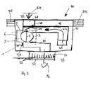
- Figure 7 shows the schematic representation of a ventilation device with integrated Blower, which is enclosed by a split sound capsule.
- a ventilation device 40 is enclosed by a housing 41.
- the Ventilation device 40 can either be in the floor of the room or in the ceiling area or also be integrated into the wall or the window of the room. According to the representation FIG. 7, the ventilation device 40 is partially penetrating a building wall 55 arranged.
- Numeral 42 designates the outside of the building while Reference numeral 43 represents a space 43 inside the building.
- a blower 44 is integrated, which is in the Figures 1 to 4 illustrated radial fan 25 or an axial fan or a Tangential blowers can act.
- the blower 44 installed in the ventilation device 40 is of a sound capsule 1 enclosed, which has a first capsule part 2 and a second capsule part 3.
- the ventilation device 40 is an inlet opening 45 for supply air, drain or A stream of air is drawn in by circulating air.
- Air flow flows through a circulating air duct 46 in the direction of flow 47 to the blower 44 to.
- Lying in front of the fan 44 in the ventilation device 40 is one by one Swivel axis 47 continuously adjustable flap 49 added.
- the flap 49 gives one Inlet opening 48 for an outside air flow 54 free or closes the suction opening 48 for outside air.
- an external air flow 54 is added to the recirculating air flow 47 and its pivot axis the blower 44 enclosed by the sound capsule 1 is conveyed into a channel 50.
- a convector 51 in which Flow rectifier 53 can be included.
- Outlet opening 52 enters the outside air / recirculating air mixture into space 43 Building.
- the position of the flap 49 is varied so that the Addition of the outside air flow 54 to the circulating air flow 47 minimal energy losses occur, but a pleasant indoor climate can be created.
- Those for theirs Swivel axis 57 adjustable flap 49 is generally not via a in Figure 7 shown, but present in the ventilation device 40 electrical drive adjusted depending on the feeling of comfort.
- the channel 50 schematically indicated in Figure 7 between the blower 44 and the Convector 51 can also be used with the positive, Heat and sound insulating connection 7, 8 with the capsule parts 2, 3 of the sound capsule 1 can be connected.
- an opening for connecting the channel 50 between the fan 44 and the Convector 51 provided, which are surrounded by an annular recess 8 is.
- the end face of the channel 50 received in the ventilation device 40 between the blower 44 and the convector 51 in this case comprises a raised, protruding rib-shaped ring element 7, which is complementary to the annular Indentation 8 in the area of the connection opening on the split sound capsule 1 is trained.
- the channel 50 between the fan 44 in the convector 51 with the split sound capsule 1 connected prevents the positive Connection between the rib-shaped in this case 7 on the Connection side of the channel 50 and the groove-like, annular recess 8 on the split sound capsule 1 the escape of air.
- the plug elements 29 which can be removed or inserted from it, which likewise comprise one or more ribs 7, which are in the capsule parts 2, 3 complementary recesses 8 cooperate.
Landscapes
- Engineering & Computer Science (AREA)
- Chemical & Material Sciences (AREA)
- Combustion & Propulsion (AREA)
- Mechanical Engineering (AREA)
- General Engineering & Computer Science (AREA)
- Structures Of Non-Positive Displacement Pumps (AREA)
- Ventilation (AREA)
Abstract
Description
- Figur 1
- eine perspektivische Ansicht einer Schallkapsel mit Hohlraum zur Aufnahme eines Gebläses,
- Figur 2
- eine perspektivische Ansicht der geteilt ausgebildeten Schallkapsel gemäß Figur 1 von der gegenüberliegenden Seite,
- Figur 3
- eine ein Lüfterrad eines Radialgebläses aufnehmende, gefügte, eine vertikal verlaufende Trennfuge aufweisende geteilte Schallkapsel,
- Figur 4
- eine Schallkapsel, welche ein Lüfterrad eines Radialgebläses umschließt und in welcher in einem Schallkapselteil ein Stopfen eingesetzt ist,
- Figur 5
- eine geteilte Schallkapsel in Schnittdarstellung,
- Figur 6
- eine Ansicht des an der Oberseite der Schallkapsel montierbaren Filterrahmens und
- Figur 7
- eine schematische Draufsicht auf eine Lüftungsvorrichtung mit Umluftkanälen sowie einem von einer geteilten Schallkapsel umgebenen Gebläse.
- 1
- Schallkapsel
- 2
- erstes Kapselteil
- 2.1
- Anlagefläche
- 3
- zweites Kapselteil
- 3.1
- Anlagefläche
- 4
- Stoßfuge
- 5
- Längsseite
- 6
- Querseite
- 7
- Rippe
- 8
- Vertiefung
- 9
- Gebläseöffnung
- 10
- gerundeter Einlauf
- 11
- Hohlraum
- 12
- erster Gebläseausblasschacht
- 13
- zweiter Gebläseausblasschacht
- 14
- Trennsteg
- 15
- Oberseite
- 16
- Unterseite
- 17
- Filtervorrichtung
- 18
- Filterrahmen
- 19
- offene Seite
- 20
- erster Längssteg
- 21
- zweiter Längssteg
- 22
- Auflagefläche Einschubfilterelement
- 23
- Steghöhe
- 24
- Stegweite (innen)
- 25
- Gebläse
- 26
- Lüfterrad
- 27
- Lüfterradschaufeln
- 28
- Schaufelring
- 29
- Stopfenelement
- 30
- Stirnfläche Stopfenelement
- 31
- Wandung Luftführungskanal
- 32
- Anlagefläche erstes Kapselteil
- 33
- Anlagefläche zweites Kapselteil
- 34
- Positionierschienen
- 35
- Oberseite
- 36
- erste Rahmenseite
- 37
- zweite Rahmenseite
- 38
- Durchtrittsöffnung
- 40
- Lüftungsvorrichtung
- 41
- Gehäuse
- 42
- Raum/Gebäudeaußenseite
- 43
- Innenraum
- 44
- Gebläse
- 45
- Umlufteintrittsöffnung
- 46
- Umluftkanal
- 47
- Strömungsrichtung Umluft
- 48
- Ansaugöffnung Außenluft
- 49
- schwenkbare Klappe
- 50
- Kanal-Gebläse Konvektor (Zuluft)
- 51
- Konvektor
- 52
- raumseitige Austrittsöffnung
- 53
- Rippen/Gleichrichter
- 54
- Außenluftstrom
- 55
- Gebäudewand/Raumwand
- 56
- austretende Umluft/Außenluftstrom
- 57
- Schwenkachse
Claims (17)
- Lüftungsvorrichtung zur Be- und Entlüftung von Räumen eines Gebäudes, ein Gebläse (25, 44) enthaltend, dem Ausblasschächte (12, 13; 50) zugeordnet sind und welches einen Umluftstrom (47) und/oder einen Außenluftstrom (54) fördert, dadurch gekennzeichnet, dass das Gebläse (25, 44) von einer geteilten Schallkapsel (1) umschlossen ist, deren Kapselteile (2, 3) so ausgebildet sind, dass entlang einer Stoßfuge (4) der Kapselteile (2, 3) eine formschlüssige, wärme- und schalldämmende Verbindung (7, 8) entsteht.
- Lüftungsvorrichtung gemäß Anspruch 1, dadurch gekennzeichnet, dass die Stoßfuge (4) zwischen dem ersten Kapselteil (2) und dem zweiten Kapselteil (3) und der Schallkapsel (1) in vertikale Richtung verläuft.
- Lüftungsvorrichtung gemäß Anspruch 1, dadurch gekennzeichnet, dass die Stoßfuge (4) zwischen dem ersten Kapselteil (2) und dem zweiten Kapselteil (3) der Schallkapsel (1) in horizontale Richtung verläuft.
- Lüftungsvorrichtung gemäß Anspruch 1, dadurch gekennzeichnet, dass an einer ersten Anlagefläche (2.1, 32) des ersten Kapselteils (2) zu Rippen (7) an einer zweiten Anlagefläche (3.1, 33) des zweiten Kapselteils (3) komplementäre Vertiefungen (8) geformt sind oder umgekehrt.
- Lüftungsvorrichtung gemäß Anspruch 1, dadurch gekennzeichnet, dass die Kapselteile (2, 3) einen Hohlraum (11) zur Aufnahme des Gebläses (25, 44) begrenzen.
- Lüftungsvorrichtung gemäß Anspruch 1, dadurch gekennzeichnet, dass die Ausblasschächte (12, 13; 50) mit dem Hohlraum (11) in Strömungsverbindung stehen und in dem ersten Kapselteil (2) und/oder in dem zweiten Kapselteil (3) der Schallkapsel (1) ausgebildet sind.
- Lüftungsvorrichtung gemäß Anspruch 1, dadurch gekennzeichnet, dass die Ausblasschächte (12, 13; 50) durch ein Verschlusselement (29) verschließbar sind.
- Lüftungsvorrichtung gemäß Anspruch 7, dadurch gekennzeichnet, dass das Verschlusselement (29) mit einer formschlüssigen Verbindung (7, 8) in den jeweils zu verschließenden Ausblasschacht (12, 13) eingelassen ist.
- Lüftungsvorrichtung gemäß Anspruch 1, dadurch gekennzeichnet, dass die Kapselteile (2, 3) der Schallkapsel (1) aus einem geformten Kunststoffmaterial mit wärmedämmenden Eigenschaften gefertigt sind.
- Lüftungsvorrichtung gemäß Anspruch 9, dadurch gekennzeichnet, dass die Kapselteile (2, 3) der Schallkapsel (1) aus expandiertem Polypropylen mit wärmedämmenden Eigenschaften gefertigt sind.
- Lüftungsvorrichtung gemäß Anspruch 1, dadurch gekennzeichnet, dass auf der eine Gebläseöffnung (9) aufweisenden Seite (15) der geteilten Schallkapsel (1) eine Filtervorrichtung (17) aufgenommen ist.
- Lüftungsvorrichtung gemäß Anspruch 11, dadurch gekennzeichnet, dass die Filtervorrichtung (17) einen Filterrahmen (18) mit einer offenen Seite (19) aufweist, an der ein Filterelement (39) in den Filterrahmen (18) einschiebbar ist.
- Lüftungsvorrichtung gemäß Anspruch 11, dadurch gekennzeichnet, dass die Filtervorrichtung (17) Positionierschienen (34) aufweist, deren Oberseite (22) Auflageflächen (35) für ein Filterelement (39) bilden.
- Lüftungsvorrichtung gemäß Anspruch 13, dadurch gekennzeichnet, dass Positionierschienen (34) der Filtervorrichtung (17) mit der Oberseite (15) der Schallkapsel (1) eine formschlüssige Verbindung (7, 8) bilden, derart, dass eine Rippe (7) in einer an der Oberseite (15) der geteilten Schallkapsel (1) ausgebildete Vertiefungen (8) eingreift.
- Lüftungsvorrichtung gemäß Anspruch 11, dadurch gekennzeichnet, dass die Filtervorrichtung (17) auf die Oberseite (15) der geteilten Schallkapsel (1) nach einer jeden Längsseite (5) oder einer jeden Querseite (6) zeigend positionierbar ist.
- Lüftungsvorrichtung gemäß Anspruch 1, dadurch gekennzeichnet, dass in ein Gehäuse (41) ein von einer geteilten Schallkapsel (1) umschlossenes Gebläse (25, 44), ein Umluft (47) zu diesem leitender Kanal (46), ein mittels einer verschwenkbaren Klappe (49) verschließ- oder freigebbarer Kanal (48), ein von dem Gebläse (25, 44) wegführender Zuluftkanal (50) sowie eine Wärmerückgewinnungseinheit aufgenommen sind.
- Lüftungsvorrichtung gemäß Anspruch 16, dadurch gekennzeichnet, dass ein vom Gebläse (44) wegführender Zuluftkanal (50) mit der geteilten Schallkapsel (1) über eine formschlüssige, wärme- und schalldämmende Verbindung (7, 8) verbunden ist.
Applications Claiming Priority (2)
| Application Number | Priority Date | Filing Date | Title |
|---|---|---|---|
| DE2003110973 DE10310973B3 (de) | 2003-03-13 | 2003-03-13 | Lüftungsvorrichtung mit Schall- und Akustikkapselung |
| DE10310973 | 2003-03-13 |
Publications (2)
| Publication Number | Publication Date |
|---|---|
| EP1477745A2 true EP1477745A2 (de) | 2004-11-17 |
| EP1477745A3 EP1477745A3 (de) | 2004-12-08 |
Family
ID=33015895
Family Applications (1)
| Application Number | Title | Priority Date | Filing Date |
|---|---|---|---|
| EP04006042A Withdrawn EP1477745A3 (de) | 2003-03-13 | 2004-03-15 | Lüftungsvorrichtung mit Schall reduzierender Kapselung |
Country Status (2)
| Country | Link |
|---|---|
| EP (1) | EP1477745A3 (de) |
| DE (1) | DE10310973B3 (de) |
Cited By (2)
| Publication number | Priority date | Publication date | Assignee | Title |
|---|---|---|---|---|
| ITTO20130008A1 (it) * | 2013-01-09 | 2014-07-10 | Thesan S P A | Dispositivo di scambio d'aria per edifici |
| EP2525103A3 (de) * | 2011-05-19 | 2014-11-26 | Liebherr-Hausgeräte Lienz GmbH | Ventilatoranordnung |
Families Citing this family (1)
| Publication number | Priority date | Publication date | Assignee | Title |
|---|---|---|---|---|
| DE202015102251U1 (de) | 2015-05-04 | 2016-08-05 | Rehau Ag & Co | Lüftereinheit zur Be- und Entlüftung von Räumen eines Gebäudes und Rahmenbaugruppe, die eine derartige Lüftereinheit umfasst |
Citations (5)
| Publication number | Priority date | Publication date | Assignee | Title |
|---|---|---|---|---|
| GB1486461A (en) * | 1975-05-13 | 1977-09-21 | Greenwood Airvac Ventilation | Ventilator incorporating centrifugal fan |
| EP0342899A2 (de) * | 1988-05-17 | 1989-11-23 | Diffusion Environmental Systems Limited | Frischluftgebläse |
| FR2706591A1 (fr) * | 1993-06-15 | 1994-12-23 | Samsung Electronics Co Ltd | Appareil de conditionnement d'air, de fenêtre, à soufflage vers le bas et muni de moyens de réduction du bruit. |
| US5943873A (en) * | 1997-05-29 | 1999-08-31 | Daewoo Electronics Co., Ltd. | Room air conditioner box having isolation wall sections |
| EP1065449A1 (de) * | 1999-06-30 | 2001-01-03 | Schiedel GmbH & Co. | Ventilationseinheit |
Family Cites Families (3)
| Publication number | Priority date | Publication date | Assignee | Title |
|---|---|---|---|---|
| DE3151386A1 (de) * | 1981-12-24 | 1983-07-14 | FSL Fenster-System-Lüftung GmbH, 6800 Mannheim | Geblaese, insbesondere einbaugeblaese |
| DE9313426U1 (de) * | 1993-09-07 | 1993-10-14 | Siegenia Frank Kg | Lüftungsvorrichtung für Räume |
| DE10122907A1 (de) * | 2001-05-11 | 2002-12-05 | Fassadensystemlueftung Gmbh & | Lüftungssystem zum dezentralen Belüften von Räumen in Gebäuden |
-
2003
- 2003-03-13 DE DE2003110973 patent/DE10310973B3/de not_active Expired - Fee Related
-
2004
- 2004-03-15 EP EP04006042A patent/EP1477745A3/de not_active Withdrawn
Patent Citations (5)
| Publication number | Priority date | Publication date | Assignee | Title |
|---|---|---|---|---|
| GB1486461A (en) * | 1975-05-13 | 1977-09-21 | Greenwood Airvac Ventilation | Ventilator incorporating centrifugal fan |
| EP0342899A2 (de) * | 1988-05-17 | 1989-11-23 | Diffusion Environmental Systems Limited | Frischluftgebläse |
| FR2706591A1 (fr) * | 1993-06-15 | 1994-12-23 | Samsung Electronics Co Ltd | Appareil de conditionnement d'air, de fenêtre, à soufflage vers le bas et muni de moyens de réduction du bruit. |
| US5943873A (en) * | 1997-05-29 | 1999-08-31 | Daewoo Electronics Co., Ltd. | Room air conditioner box having isolation wall sections |
| EP1065449A1 (de) * | 1999-06-30 | 2001-01-03 | Schiedel GmbH & Co. | Ventilationseinheit |
Cited By (3)
| Publication number | Priority date | Publication date | Assignee | Title |
|---|---|---|---|---|
| EP2525103A3 (de) * | 2011-05-19 | 2014-11-26 | Liebherr-Hausgeräte Lienz GmbH | Ventilatoranordnung |
| ITTO20130008A1 (it) * | 2013-01-09 | 2014-07-10 | Thesan S P A | Dispositivo di scambio d'aria per edifici |
| EP2754975A1 (de) * | 2013-01-09 | 2014-07-16 | Thesan S.p.A. | Luftaustauschvorrichtung für Gebäude |
Also Published As
| Publication number | Publication date |
|---|---|
| EP1477745A3 (de) | 2004-12-08 |
| DE10310973B3 (de) | 2005-06-02 |
Similar Documents
| Publication | Publication Date | Title |
|---|---|---|
| EP1832818B1 (de) | Lüftungsanlage | |
| DE3208392A1 (de) | Lueftungsgeraet zum be- und entlueften von raeumen | |
| DE2910371C2 (de) | ||
| DE202005011482U1 (de) | Wärmerückgewinnungsgerät | |
| DE4143036A1 (de) | Belueftungseinrichtung fuer raeume | |
| DE102005011222A1 (de) | Lüftungsanlage | |
| DE102008020941B4 (de) | Luftführungselement zum Zuführen und/oder Abführen von Luft | |
| DE3441769A1 (de) | Lueftungsvorrichtung fuer raeume | |
| DE10310973B3 (de) | Lüftungsvorrichtung mit Schall- und Akustikkapselung | |
| DE10109753A1 (de) | Lüftungsgerät für die Gebäudelüftung | |
| CH620026A5 (en) | Device intended for installation in the region of a window for the forced ventilation of rooms | |
| EP2645009B1 (de) | Lüftungsanlage | |
| DE202006017606U1 (de) | Türanordnung | |
| EP0855560B1 (de) | Lüftungsvorrichtung | |
| CH663079A5 (de) | Lueftungsvorrichtung fuer den einbau in eine fenster-, tuer- oder andere wandoeffnung eines gebaeudes. | |
| DE4104965C2 (de) | Gehäuse zur Aufnahme eines Gebläses | |
| DE3928294A1 (de) | Gehaeuse fuer lueftungsgeraete, klimageraete oder dergleichen | |
| DE4226634C2 (de) | Entlüftungsgerät | |
| DE10106646C1 (de) | Mauerkasten für Abluft- und Zuluft-Durchleitung durch eine Wand | |
| EP0149053B1 (de) | Lüftungsvorrichtung für Räume | |
| DE102007055245A1 (de) | Türanordnung | |
| EP3623715A2 (de) | Mauerkasten-system für ein lüftungssystem | |
| DE102016009790B3 (de) | Raumbe- und -entlüftungsgerät zur Montage in Durchbrüchen von Wänden oder Decken | |
| EP0828118A2 (de) | Lüftungsvorrichtung zum gleichzeitigen Be- und Entlüften von Räumen | |
| DE19964600B4 (de) | Gehäuse für eine lufttechnische Einrichtung |
Legal Events
| Date | Code | Title | Description |
|---|---|---|---|
| PUAI | Public reference made under article 153(3) epc to a published international application that has entered the european phase |
Free format text: ORIGINAL CODE: 0009012 |
|
| PUAL | Search report despatched |
Free format text: ORIGINAL CODE: 0009013 |
|
| AK | Designated contracting states |
Kind code of ref document: A2 Designated state(s): AT BE BG CH CY CZ DE DK EE ES FI FR GB GR HU IE IT LI LU MC NL PL PT RO SE SI SK TR |
|
| AX | Request for extension of the european patent |
Extension state: AL LT LV MK |
|
| AK | Designated contracting states |
Kind code of ref document: A3 Designated state(s): AT BE BG CH CY CZ DE DK EE ES FI FR GB GR HU IE IT LI LU MC NL PL PT RO SE SI SK TR |
|
| AX | Request for extension of the european patent |
Extension state: AL LT LV MK |
|
| 17P | Request for examination filed |
Effective date: 20050602 |
|
| AKX | Designation fees paid |
Designated state(s): AT BE BG CH CY CZ DE DK EE ES FI FR GB GR HU IE IT LI LU MC NL PL PT RO SE SI SK TR |
|
| AXX | Extension fees paid |
Extension state: LT Payment date: 20050602 |
|
| 17Q | First examination report despatched |
Effective date: 20051202 |
|
| GRAP | Despatch of communication of intention to grant a patent |
Free format text: ORIGINAL CODE: EPIDOSNIGR1 |
|
| RIN1 | Information on inventor provided before grant (corrected) |
Inventor name: HOLTZ, HANS-JOCHIM |
|
| STAA | Information on the status of an ep patent application or granted ep patent |
Free format text: STATUS: THE APPLICATION IS DEEMED TO BE WITHDRAWN |
|
| 18D | Application deemed to be withdrawn |
Effective date: 20080205 |