EP0342899A2 - Frischluftgebläse - Google Patents
Frischluftgebläse Download PDFInfo
- Publication number
- EP0342899A2 EP0342899A2 EP89304889A EP89304889A EP0342899A2 EP 0342899 A2 EP0342899 A2 EP 0342899A2 EP 89304889 A EP89304889 A EP 89304889A EP 89304889 A EP89304889 A EP 89304889A EP 0342899 A2 EP0342899 A2 EP 0342899A2
- Authority
- EP
- European Patent Office
- Prior art keywords
- box
- acoustic
- ventilator
- fan
- wall
- Prior art date
- Legal status (The legal status is an assumption and is not a legal conclusion. Google has not performed a legal analysis and makes no representation as to the accuracy of the status listed.)
- Granted
Links
- 239000012814 acoustic material Substances 0.000 claims abstract description 13
- 238000012856 packing Methods 0.000 claims abstract description 10
- 239000000463 material Substances 0.000 claims abstract description 7
- 239000011490 mineral wool Substances 0.000 claims description 8
- 238000004378 air conditioning Methods 0.000 claims description 3
- 239000011810 insulating material Substances 0.000 claims 1
- 238000007667 floating Methods 0.000 abstract description 2
- 239000000725 suspension Substances 0.000 abstract 1
- 229910052751 metal Inorganic materials 0.000 description 3
- 239000002184 metal Substances 0.000 description 3
- 230000000717 retained effect Effects 0.000 description 2
- 238000009423 ventilation Methods 0.000 description 2
- 239000004677 Nylon Substances 0.000 description 1
- 239000004411 aluminium Substances 0.000 description 1
- 229910052782 aluminium Inorganic materials 0.000 description 1
- XAGFODPZIPBFFR-UHFFFAOYSA-N aluminium Chemical compound [Al] XAGFODPZIPBFFR-UHFFFAOYSA-N 0.000 description 1
- 230000000712 assembly Effects 0.000 description 1
- 238000000429 assembly Methods 0.000 description 1
- 239000011449 brick Substances 0.000 description 1
- 239000011469 building brick Substances 0.000 description 1
- 230000008878 coupling Effects 0.000 description 1
- 238000010168 coupling process Methods 0.000 description 1
- 238000005859 coupling reaction Methods 0.000 description 1
- 230000002939 deleterious effect Effects 0.000 description 1
- 239000003822 epoxy resin Substances 0.000 description 1
- 239000011152 fibreglass Substances 0.000 description 1
- 239000003292 glue Substances 0.000 description 1
- 238000004519 manufacturing process Methods 0.000 description 1
- 238000000034 method Methods 0.000 description 1
- 229920001778 nylon Polymers 0.000 description 1
- 239000004033 plastic Substances 0.000 description 1
- 229920000647 polyepoxide Polymers 0.000 description 1
- 238000007493 shaping process Methods 0.000 description 1
- 238000013022 venting Methods 0.000 description 1
- 210000002268 wool Anatomy 0.000 description 1
Images
Classifications
-
- F—MECHANICAL ENGINEERING; LIGHTING; HEATING; WEAPONS; BLASTING
- F24—HEATING; RANGES; VENTILATING
- F24F—AIR-CONDITIONING; AIR-HUMIDIFICATION; VENTILATION; USE OF AIR CURRENTS FOR SCREENING
- F24F7/00—Ventilation
- F24F7/007—Ventilation with forced flow
-
- F—MECHANICAL ENGINEERING; LIGHTING; HEATING; WEAPONS; BLASTING
- F24—HEATING; RANGES; VENTILATING
- F24F—AIR-CONDITIONING; AIR-HUMIDIFICATION; VENTILATION; USE OF AIR CURRENTS FOR SCREENING
- F24F13/00—Details common to, or for air-conditioning, air-humidification, ventilation or use of air currents for screening
- F24F13/24—Means for preventing or suppressing noise
Definitions
- the present invention relates to an acoustic fresh air ventilator suitable for ventilating a compartment.
- Acoustic fresh air ventilators commonly provide a means of introducing fresh air into a compartment through a compartment wall and can include a means for extracting stale air from the compartment.
- References hereafter to "wall" when relating to a compartment is meant to include the ceiling or even the floor of the compartment.
- Known acoustic fresh air ventilators often include a fan for forced ventilation.
- a motor driven fan mounted within a box or housing whose sides are provided with a layer of acoustic material, the fan being fixed to one wall and the box is so designed as to be mounted in a hole in a wall of the compartment to be ventilated.
- the fan must be about 90mm wide by about 180mm in diameter, resulting in a box of about 220mm by 140mm by 250mm. This allows for acoustic lagging on the interior of the sides of the box of about 15mm thick.
- the hole to accommodate the box in the wall is necessarily of a similar size to that of the box which results in a hole which is structurally undesirable and may be aesthetically unappealing.
- a further object of the invention is to improve the acoustic performance of the ventilator.
- An acoustic fresh air ventilator comprises a box mountable to a compartment wall, one or more fans within the box, an inlet, an outlet conduit for the or each fan, at least one said inlet or said outlet extending from the box to a ducting element mounted to the box and extending from the box for extension through the wall, the box being packed with acoustic material.
- An acoustic fresh air ventilator comprises a box mountable to a compartment wall, one or more fans within the box with suitable conduits from the fan(s) to the outside of the box, the box being packed with acoustic material, wherein the or each fan is unattached to the box and is retained in a predetermined position within the box by the acoustic material.
- the size of the hole through the wall need be no more than one standard brick size.
- the box can be provided with thicker acoustic lining than the known ventilator because there is no requirement to limit the box size relative to the hole through the wall. This results in a substantial noise reduction.
- the acoustic material is suitably a mineral wool such as rockwool and is contained or structured in such a way that internal conduits between the box sides and fan(s) are formed by shaping the wool packing.
- this acoustic material is in several pieces or pads so that the pieces or pads can be easily removed and replaced to access the fan(s).
- the or each external ducting element is preferably formed as a perforated tube surrounded by acoustic material which is in turn surrounded by a further tube.
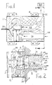
- an acoustic ventilator with a six sided box 1.
- the size of the box containing two fans is 603mm by 405mm by 205mm.
- One side 3 of the box is a lid which may be riveted, bolted or hinged to one or more of the other sides.
- the box is provided with wall mounting means comprising brackets 4 for mounting the box to a wall 5.
- the box Within the box are two identical motorised centrifugal fans 8 and 10. Suitably these fans are centrifugal fans with single side inlets 12 and 14 respectively.
- the fans in the embodiment have a capacity of 86 m3/h, the fans run up to 2300 rpm and have a self noise level of 51 dBA.
- the outlets 16 and 18 are substantially square in cross-section and vent into internal conduits 20, 22 which are formed as will be described below within sealed rockwool pads.
- the fan inlets 24, 26 are also formed within rockwool pads. The fans remain unbolted to the box and are merely located by the acoustic packing within the box. Cabling 28 from the fans extends to an external control either remote or mounted on the exterior of the box.
- the fan control may be mounted in a suitable place in the box or partially in the box and partially without the box on the lid 3.
- conduits 20, 22, 24 and 26 within the acoustic packing is achieved in the case of conduits 20 and 26 by providing a base liner pad 30 of rockwool enclosed in a pad of nylon or pervious fibre glass material.
- This pad is suitably strengthened by glue or an epoxy resin to make the pad rigid and to keep conduits 20 and 26 in a predetermined form.
- a second pad 32 forms one side 34 of conduit 24 and part of walls 33 of conduit 22.
- Further pads 36, 38 and 40 form the remaining parts of conduits 22 and 24.
- the padding material prevents the rockwool from migrating within the box.
- the rockwool used is a heavy density material of 200 kg/m3. Any space within the box not occupied by conduits, the fans, or associated electrical elements is therefore filled with acoustic packing which around the fans is generally much thicker than that provided in known prior art assemblies.
- the box has an inlet ducting element 42 and an outlet ducting element 44 formed from metal or plastic external tubes 46 and 46′ with perforated aluminium internal tubes 48 and 48′. Between the external and internal tubes is more acoustic material 50 and 50′. Flexible tubes can be joined to ducting elements 42 and 44 particularly when the ventilator is required for ceiling location.
- the ducting elements are mounted to the box as close together as acoustically desirable.
- the larger inlet element 42 with an external diameter of about 100mm is spaced about 25mm from the smaller outlet element 44 which has an external diameter of about 75mm.
- the resulting hole 70 defined by wall surfaces 71, 72 need only be about 200mm by 100mm which is within a standard sized building brick of about 225mm by 100mm.
- the centre 45 of element 44 is offset from centre 9 of the outlet of fan 8. This is necessary due to the near abutment of fan 8 with fan 10.
- the misalignment of centres 9 and 45 is not deleterious due to the spacing of fan 8 from its box sides by pad 30.
- Some improvement in misalignment could be achieved by rotating fan 10 through 180 degrees and venting conduit 22 through another side wall. Equally a different handed fan could replace fan 10.
- the chosen configuration has been chosen for simplicity and acoustic performance.
- a further external ducting element 52 is mounted to the box at the outlet of conduit 22 which may be used for coupling the ventilator to an air conditioning unit shown diagrammatically at 60.
- conduit 22 communicates directly with the air conditioning unit.
- Conduit 24 terminates in a perforated plate or area 54 in one side of the box 1.
- conduits 20, 22, 24 and 26 are cast in two blocks forming the whole of the acoustic packing for the box.
- the ventilator of the invention provides a simple but convenient method of introducing fresh air and extracting stale air into and from a compartment without the need to provide a large hole in a wall of the compartment.
- the acoustic performance is extremely good due to the "floating" of the fan(s) in the ventilator box or housing, without the fan(s) being mounted by bolting or the like to the box.
- the opportunity has been taken in the embodiment of the invention to eliminate metal conduits within the box or housing which reduces the cost of assembly, manufacture and again improves the acoustic performance.
Landscapes
- Engineering & Computer Science (AREA)
- Chemical & Material Sciences (AREA)
- Combustion & Propulsion (AREA)
- Mechanical Engineering (AREA)
- General Engineering & Computer Science (AREA)
- Structures Of Non-Positive Displacement Pumps (AREA)
- Gas Separation By Absorption (AREA)
- Percussion Or Vibration Massage (AREA)
- Soundproofing, Sound Blocking, And Sound Damping (AREA)
- Duct Arrangements (AREA)
- Packages (AREA)
Priority Applications (1)
| Application Number | Priority Date | Filing Date | Title |
|---|---|---|---|
| AT89304889T ATE83550T1 (de) | 1988-05-17 | 1989-05-15 | Frischluftgeblaese. |
Applications Claiming Priority (2)
| Application Number | Priority Date | Filing Date | Title |
|---|---|---|---|
| GB8811603 | 1988-05-17 | ||
| GB8811603A GB2218799A (en) | 1988-05-17 | 1988-05-17 | Sound attenuating ventilator |
Publications (3)
| Publication Number | Publication Date |
|---|---|
| EP0342899A2 true EP0342899A2 (de) | 1989-11-23 |
| EP0342899A3 EP0342899A3 (en) | 1990-05-16 |
| EP0342899B1 EP0342899B1 (de) | 1992-12-16 |
Family
ID=10637002
Family Applications (1)
| Application Number | Title | Priority Date | Filing Date |
|---|---|---|---|
| EP89304889A Expired - Lifetime EP0342899B1 (de) | 1988-05-17 | 1989-05-15 | Frischluftgebläse |
Country Status (5)
| Country | Link |
|---|---|
| EP (1) | EP0342899B1 (de) |
| AT (1) | ATE83550T1 (de) |
| DE (1) | DE68903874T2 (de) |
| ES (1) | ES2037420T3 (de) |
| GB (1) | GB2218799A (de) |
Cited By (5)
| Publication number | Priority date | Publication date | Assignee | Title |
|---|---|---|---|---|
| US5260523A (en) * | 1990-11-20 | 1993-11-09 | Valmet Paper Machinery, Inc. | Absorptive sound attenuator, in particular for air ducts in paper mills |
| EP1103768A3 (de) * | 1999-11-23 | 2003-09-10 | Rosenberg Ventilatoren GmbH | Lüftungssystem |
| EP1477745A3 (de) * | 2003-03-13 | 2004-12-08 | Erwin Müller GmbH | Lüftungsvorrichtung mit Schall reduzierender Kapselung |
| EP1840478A1 (de) * | 2006-03-29 | 2007-10-03 | Fensterfabrik Albisrieden Ag | Fensterbereich |
| DE202015102251U1 (de) * | 2015-05-04 | 2016-08-05 | Rehau Ag & Co | Lüftereinheit zur Be- und Entlüftung von Räumen eines Gebäudes und Rahmenbaugruppe, die eine derartige Lüftereinheit umfasst |
Families Citing this family (1)
| Publication number | Priority date | Publication date | Assignee | Title |
|---|---|---|---|---|
| DE102008020941B4 (de) * | 2008-04-25 | 2020-09-24 | Ventomaxx Gmbh | Luftführungselement zum Zuführen und/oder Abführen von Luft |
Family Cites Families (7)
| Publication number | Priority date | Publication date | Assignee | Title |
|---|---|---|---|---|
| US3125286A (en) * | 1964-03-17 | sanders | ||
| BE793511A (fr) * | 1971-12-31 | 1973-04-16 | F H Biddle Ltd | Appareil de ventilation |
| US3789747A (en) * | 1972-12-15 | 1974-02-05 | Industrial Acoustics Co | Ventilated acoustic structural panel |
| GB1486461A (en) * | 1975-05-13 | 1977-09-21 | Greenwood Airvac Ventilation | Ventilator incorporating centrifugal fan |
| DE2910371A1 (de) * | 1979-03-16 | 1980-10-02 | Eberspaecher J | Belueftungsvorrichtung fuer abgedichtete raeume |
| FR2505416B1 (fr) * | 1981-05-11 | 1986-09-12 | Cogema | Installation de ventilation, notamment ventilateur industriel |
| DE8224454U1 (de) * | 1982-08-30 | 1982-11-25 | Siegenia-Frank Kg, 5900 Siegen | Lueftungsvorrichtung zur anordnung an gebaeudewaenden |
-
1988
- 1988-05-17 GB GB8811603A patent/GB2218799A/en not_active Withdrawn
-
1989
- 1989-05-15 EP EP89304889A patent/EP0342899B1/de not_active Expired - Lifetime
- 1989-05-15 AT AT89304889T patent/ATE83550T1/de not_active IP Right Cessation
- 1989-05-15 ES ES198989304889T patent/ES2037420T3/es not_active Expired - Lifetime
- 1989-05-15 DE DE8989304889T patent/DE68903874T2/de not_active Expired - Fee Related
Cited By (5)
| Publication number | Priority date | Publication date | Assignee | Title |
|---|---|---|---|---|
| US5260523A (en) * | 1990-11-20 | 1993-11-09 | Valmet Paper Machinery, Inc. | Absorptive sound attenuator, in particular for air ducts in paper mills |
| EP1103768A3 (de) * | 1999-11-23 | 2003-09-10 | Rosenberg Ventilatoren GmbH | Lüftungssystem |
| EP1477745A3 (de) * | 2003-03-13 | 2004-12-08 | Erwin Müller GmbH | Lüftungsvorrichtung mit Schall reduzierender Kapselung |
| EP1840478A1 (de) * | 2006-03-29 | 2007-10-03 | Fensterfabrik Albisrieden Ag | Fensterbereich |
| DE202015102251U1 (de) * | 2015-05-04 | 2016-08-05 | Rehau Ag & Co | Lüftereinheit zur Be- und Entlüftung von Räumen eines Gebäudes und Rahmenbaugruppe, die eine derartige Lüftereinheit umfasst |
Also Published As
| Publication number | Publication date |
|---|---|
| ES2037420T3 (es) | 1993-06-16 |
| DE68903874D1 (de) | 1993-01-28 |
| EP0342899A3 (en) | 1990-05-16 |
| GB8811603D0 (en) | 1988-06-22 |
| DE68903874T2 (de) | 1993-04-22 |
| EP0342899B1 (de) | 1992-12-16 |
| GB2218799A (en) | 1989-11-22 |
| ATE83550T1 (de) | 1993-01-15 |
Similar Documents
| Publication | Publication Date | Title |
|---|---|---|
| US5672052A (en) | Blower muffling apparatus | |
| AU707670B2 (en) | Air blower and filter assemblies | |
| US5151018A (en) | Sound attenuation chamber | |
| US4699640A (en) | Clean room having partially different degree of cleanliness | |
| US5728979A (en) | Air handling structure for fan inlet and outlet | |
| US5473123A (en) | Air handling structure for fan inlet and outlet | |
| KR100299406B1 (ko) | 문과냉각기를갖춘콘트롤박스 | |
| US9004995B1 (en) | Wall curb for air treatment system | |
| CA2191049A1 (en) | Central vacuum with acoustical damping | |
| US3799703A (en) | Ventilating unit for sound control room | |
| US5587563A (en) | Air handling structure for pan inlet and outlet | |
| EP0342899B1 (de) | Frischluftgebläse | |
| JPS621615Y2 (de) | ||
| GB2172094A (en) | An outdoor unit for an air conditioning apparatus of a through-the-wall multitype | |
| US4037527A (en) | Grain drying apparatus | |
| GB2044438A (en) | Ventilating apparatus for sealed spaces | |
| JP3711064B2 (ja) | 空気調和装置 | |
| EP1092116A2 (de) | Kompakte luftbehandlungseinheit mit eingebautem schalldämpfer | |
| EP1795819B1 (de) | Klimaanlage | |
| EP0789196B1 (de) | Klimaanlage mit exzentrisch angeordnetem Gebläse | |
| EP1693626B1 (de) | Luftklimatisierer mit deckenaufhängung | |
| JP4382904B2 (ja) | ビルトイン型空気調和装置 | |
| JPS6274427A (ja) | フイルタユニツト | |
| JPH0216205Y2 (de) | ||
| JPH0340334Y2 (de) |
Legal Events
| Date | Code | Title | Description |
|---|---|---|---|
| PUAI | Public reference made under article 153(3) epc to a published international application that has entered the european phase |
Free format text: ORIGINAL CODE: 0009012 |
|
| AK | Designated contracting states |
Kind code of ref document: A2 Designated state(s): AT BE CH DE ES FR GB GR IT LI LU NL SE |
|
| PUAL | Search report despatched |
Free format text: ORIGINAL CODE: 0009013 |
|
| AK | Designated contracting states |
Kind code of ref document: A3 Designated state(s): AT BE CH DE ES FR GB GR IT LI LU NL SE |
|
| 17P | Request for examination filed |
Effective date: 19901024 |
|
| 17Q | First examination report despatched |
Effective date: 19910123 |
|
| GRAA | (expected) grant |
Free format text: ORIGINAL CODE: 0009210 |
|
| AK | Designated contracting states |
Kind code of ref document: B1 Designated state(s): AT BE CH DE ES FR GB GR IT LI LU NL SE |
|
| PG25 | Lapsed in a contracting state [announced via postgrant information from national office to epo] |
Ref country code: IT Free format text: LAPSE BECAUSE OF FAILURE TO SUBMIT A TRANSLATION OF THE DESCRIPTION OR TO PAY THE FEE WITHIN THE PRE;WARNING: LAPSES OF ITALIAN PATENTS WITH EFFECTIVE DATE BEFORE 2007 MAY HAVE OCCURRED AT ANY TIME BEFORE 2007. THE CORRECT EFFECTIVE DATE MAY BE DIFFERENT FROM THE ONE RECORDED.SCRIBED TIME-LIMIT Effective date: 19921216 Ref country code: CH Effective date: 19921216 Ref country code: AT Effective date: 19921216 Ref country code: LI Effective date: 19921216 Ref country code: NL Effective date: 19921216 Ref country code: FR Effective date: 19921216 Ref country code: SE Effective date: 19921216 Ref country code: BE Effective date: 19921216 |
|
| REF | Corresponds to: |
Ref document number: 83550 Country of ref document: AT Date of ref document: 19930115 Kind code of ref document: T |
|
| REF | Corresponds to: |
Ref document number: 68903874 Country of ref document: DE Date of ref document: 19930128 |
|
| PG25 | Lapsed in a contracting state [announced via postgrant information from national office to epo] |
Ref country code: GR Free format text: LAPSE BECAUSE OF FAILURE TO SUBMIT A TRANSLATION OF THE DESCRIPTION OR TO PAY THE FEE WITHIN THE PRESCRIBED TIME-LIMIT Effective date: 19930319 |
|
| REG | Reference to a national code |
Ref country code: CH Ref legal event code: PL |
|
| EN | Fr: translation not filed | ||
| NLV1 | Nl: lapsed or annulled due to failure to fulfill the requirements of art. 29p and 29m of the patents act | ||
| PG25 | Lapsed in a contracting state [announced via postgrant information from national office to epo] |
Ref country code: LU Free format text: LAPSE BECAUSE OF NON-PAYMENT OF DUE FEES Effective date: 19930531 |
|
| PGFP | Annual fee paid to national office [announced via postgrant information from national office to epo] |
Ref country code: GB Payment date: 19930614 Year of fee payment: 5 |
|
| REG | Reference to a national code |
Ref country code: ES Ref legal event code: FG2A Ref document number: 2037420 Country of ref document: ES Kind code of ref document: T3 |
|
| PGFP | Annual fee paid to national office [announced via postgrant information from national office to epo] |
Ref country code: ES Payment date: 19930630 Year of fee payment: 5 |
|
| PGFP | Annual fee paid to national office [announced via postgrant information from national office to epo] |
Ref country code: DE Payment date: 19930729 Year of fee payment: 5 |
|
| PLBI | Opposition filed |
Free format text: ORIGINAL CODE: 0009260 |
|
| 26 | Opposition filed |
Opponent name: SIEGENIA-FRANK KG Effective date: 19930906 |
|
| PG25 | Lapsed in a contracting state [announced via postgrant information from national office to epo] |
Ref country code: GB Effective date: 19940515 |
|
| PG25 | Lapsed in a contracting state [announced via postgrant information from national office to epo] |
Ref country code: ES Free format text: LAPSE BECAUSE OF NON-PAYMENT OF DUE FEES Effective date: 19940516 |
|
| GBPC | Gb: european patent ceased through non-payment of renewal fee |
Effective date: 19940515 |
|
| PG25 | Lapsed in a contracting state [announced via postgrant information from national office to epo] |
Ref country code: DE Effective date: 19950201 |
|
| RDAG | Patent revoked |
Free format text: ORIGINAL CODE: 0009271 |
|
| STAA | Information on the status of an ep patent application or granted ep patent |
Free format text: STATUS: PATENT REVOKED |
|
| 27W | Patent revoked |
Effective date: 19950812 |