EP1477576B1 - Verbundwerkstoff auf magnesiumbasis und herstellungsverfahren dafür - Google Patents
Verbundwerkstoff auf magnesiumbasis und herstellungsverfahren dafür Download PDFInfo
- Publication number
- EP1477576B1 EP1477576B1 EP03705207A EP03705207A EP1477576B1 EP 1477576 B1 EP1477576 B1 EP 1477576B1 EP 03705207 A EP03705207 A EP 03705207A EP 03705207 A EP03705207 A EP 03705207A EP 1477576 B1 EP1477576 B1 EP 1477576B1
- Authority
- EP
- European Patent Office
- Prior art keywords
- magnesium
- composite material
- base composite
- weight
- magnesium base
- Prior art date
- Legal status (The legal status is an assumption and is not a legal conclusion. Google has not performed a legal analysis and makes no representation as to the accuracy of the status listed.)
- Expired - Lifetime
Links
Images


Classifications
-
- C—CHEMISTRY; METALLURGY
- C22—METALLURGY; FERROUS OR NON-FERROUS ALLOYS; TREATMENT OF ALLOYS OR NON-FERROUS METALS
- C22C—ALLOYS
- C22C23/00—Alloys based on magnesium
- C22C23/02—Alloys based on magnesium with aluminium as the next major constituent
-
- C—CHEMISTRY; METALLURGY
- C22—METALLURGY; FERROUS OR NON-FERROUS ALLOYS; TREATMENT OF ALLOYS OR NON-FERROUS METALS
- C22C—ALLOYS
- C22C23/00—Alloys based on magnesium
-
- C—CHEMISTRY; METALLURGY
- C22—METALLURGY; FERROUS OR NON-FERROUS ALLOYS; TREATMENT OF ALLOYS OR NON-FERROUS METALS
- C22C—ALLOYS
- C22C32/00—Non-ferrous alloys containing at least 5% by weight but less than 50% by weight of oxides, carbides, borides, nitrides, silicides or other metal compounds, e.g. oxynitrides, sulfides, whether added as such or formed in situ
-
- F—MECHANICAL ENGINEERING; LIGHTING; HEATING; WEAPONS; BLASTING
- F16—ENGINEERING ELEMENTS AND UNITS; GENERAL MEASURES FOR PRODUCING AND MAINTAINING EFFECTIVE FUNCTIONING OF MACHINES OR INSTALLATIONS; THERMAL INSULATION IN GENERAL
- F16D—COUPLINGS FOR TRANSMITTING ROTATION; CLUTCHES; BRAKES
- F16D69/00—Friction linings; Attachment thereof; Selection of coacting friction substances or surfaces
- F16D69/02—Composition of linings ; Methods of manufacturing
- F16D69/027—Compositions based on metals or inorganic oxides
-
- F—MECHANICAL ENGINEERING; LIGHTING; HEATING; WEAPONS; BLASTING
- F16—ENGINEERING ELEMENTS AND UNITS; GENERAL MEASURES FOR PRODUCING AND MAINTAINING EFFECTIVE FUNCTIONING OF MACHINES OR INSTALLATIONS; THERMAL INSULATION IN GENERAL
- F16D—COUPLINGS FOR TRANSMITTING ROTATION; CLUTCHES; BRAKES
- F16D2200/00—Materials; Production methods therefor
- F16D2200/0034—Materials; Production methods therefor non-metallic
- F16D2200/0039—Ceramics
- F16D2200/0043—Ceramic base, e.g. metal oxides or ceramic binder
Definitions
- the present invention relates to a magnesium base composite material having excellent mechanical characteristics and corrosion resistance, and its manufacturing method.
- Japanese Unexamined Patent Publication No. 6-81068 discloses a method of manufacturing a magnesium base composite material in which Mg 2 Si is synthesized by a reaction of Mg of a matrix and Si when a magnesium alloy of high Si content is injection-molded in a semi-solid state, and the Mg 2 Si particles are dispersed.
- Japanese Unexamined Patent Publication No. 8-41564 discloses a magnesium base composite material provided by a casting method, in which Mg 2 Si particles and SiC particles are dispersed.
- Japanese Unexamined Patent Publication No. 2000-17352 discloses a magnesium base composite material in which spherical Mg 2 Si particles are dispersed and its manufacturing method by a casting method.
- the Japanese patent JP 57047843 discloses a composite magnesium material requiring higher strength and wear resistance, which produced by adding (1-15%) of a ceramic particle such as SiO 2 (and 1-8% graphit) to molten magnesium.
- the inventors of the present invention have proposed a method in which mixture powder provided by combining matrix powder comprising magnesium (Mg) with silicon (Si) powder is pressed to be molded by powder metallurgy technique and this is heated and held at an appropriate solid-phase temperature which is less than a melting point of Mg in a controlled heating atmosphere to generate fine Mg 2 Si by reaction between Mg and Si powder, so that the fine Mg 2 Si are dispersed in a matrix.
- magnesium base composite material, magnesium base composite material precursor, and their manufacturing method was applied for patent as Patent Application No. 2001-292117, on September 25 in 2001 and "magnesium base composite material, magnesium base composite material precursor, and their manufacturing method” was applied for patent as Patent Application No. 2001-292118, on September 25 in 2001.
- magnesium base composite material provided by the above method proposed by the inventors of the present invention, since fine Mg 2 Si particles are uniformly dispersed, mechanical characteristics such as strength or hardness of the composite material is improved, and since hard Mg 2 Si particles are uniformly dispersed, abrasion resistance of the composite material can be improved.
- this composite material is used as a material for frictional sliding component, although the abrasion resistance of the composite material itself is improved, there is a problem in which it makes an attack on an opponent material when the opponent material is a relatively soft material.
- a magnesium base composite material according to the present invention comprises magnesium silicide (Mg 2 Si), magnesium oxide (MgO) and magnesium.
- the magnesium base composite material may further comprise a SiO 2 component.
- the Mg 2 Si and MgO are uniformly dispersed in the magnesium base composite material.
- Mg 2 Si is comprised in 100 parts by weight of the magnesium base composite material.
- MgO is comprised in 100 parts of the magnesium base composite material.
- the compound particles comprise magnesium silicide (Mg 2 Si) and magnesium oxide (MgO).
- the compound particles may further comprise SiO 2 component.
- the magnesium silicide is comprised in 100 parts by weight of the magnesium group composite material. Further preferably, 5 to 8 parts by weight of the magnesium silicide is comprised.
- the magnesium oxide is comprised in 100 parts by weight of the magnesium group composite material. Further preferably, 5 or more parts and 8 or less parts of the magnesium oxide is comprised.
- the magnesium base composite material may comprise graphite powder as a solid lubricating agent.
- a graphite powder content is 0.5 to 3% by weight in the magnesium base composite material.
- a method of manufacturing a magnesium base composite material comprises a step of providing a mixture by mixing a first material comprising magnesium (Mg) and a second material containing a SiO 2 component, a step of providing a pressed powder molded body by putting the mixture into a predetermined container or a mold and applying pressure thereto and a step of heating the pressed powder molded body in an inert gas atmosphere or in vacuum, in which magnesium silicide (Mg 2 Si) and magnesium oxide (MgO) are generated by a reaction of Mg and SiOz in the mixture at the heating step to manufacture the magnesium base composite material comprising Mg 2 Si, MgO and Mg.
- Mg 2 Si magnesium silicide
- MgO magnesium oxide
- a heating temperature at the heating step is 250°C or more.
- Mg 2 Si and MgO are uniformly dispersed in the magnesium base composite material.
- the magnesium group composite material may further comprise SiO 2 .
- SiO 2 is uniformly dispersed in the magnesium base composite material.
- Mg 2 Si is contained in 100 parts by weight of the magnesium base composite material.
- MgO is contained in 100 parts by weight of the magnesium base composite material.
- a method of manufacturing a magnesium base composite material comprises a step of providing a mixture by mixing a first material comprising magnesium and a second material containing a SiO 2 component, a step of providing a pressed powder molded body by applying pressure to the mixture and a step of heating the pressed powder molded body in an inert gas atmosphere or in vacuum to generate magnesium silicide (Mg 2 Si) and magnesium oxide (MgO) in a magnesium alloy body by a reaction of Mg and SiO 2 in the pressed powder molded body.
- Mg 2 Si magnesium silicide
- MgO magnesium oxide
- a step of grinding the mixture may be provided prior to the step of providing the pressed powder molded body. Furthermore, a step of pressure bonding the mixture may be provided after the step of grinding the mixture. Still further, a step of crushing the mixture may be provided after the step of pressure bonding the mixture.
- a heating temperature of the pressed powder molded body is 250°C or more and not more than a melting point of magnesium.
- a step of forming a new phase in magnesium in the first material by grinding and/or pressure bonding and/or crushing the mixture may be further provided prior to the step of providing the pressed powder molded body.
- a magnesium base composite material of the present invention comprises magnesium silicide (Mg 2 Si), magnesium oxide (MgO) and magnesium.
- Mg 2 Si contained in the composite material of the present invention has a coefficient of thermal expansion lower than that of magnesium, high rigidity, high hardness and low specific gravity and it is superior in heat resistance and corrosion resistance.
- Fine particles of Mg 2 Si are preferably dispersed uniformly in the composite material of the present invention.
- the composite material of the present invention comprises fine particles of Mg 2 Si, and comprises uniformly dispersed fine particles of Mg 2 Si in particular, mechanical characteristics (strength and/or hardness, for example), wear resistance and corrosion resistance thereof can be improved.
- uniformly dispersed Mg 2 Si means that a distance between the particles of Mg 2 Si is about 300 ⁇ m at a maximum.
- the particles of Mg 2 Si must not agglutinate, segregate nor form networks. As the distance between the particles of Mg 2 Si is decreased, the mechanical characteristics such as tensile strength are improved.
- the material of the present invention comprises 3 or more parts by weight, and preferably 5 or more parts by weight of Mg 2 Si based on 100 parts by weight of the material.
- the composite material may comprise 15 or less parts, and preferably 8 or less parts by weight of Mg 2 Si based on 100 parts by weight of the material.
- MgO contained in the composite material of the present invention can improve the mechanical characteristics (strength and/or hardness, for example) of the composite material. In addition, MgO can improve opponent aggression.
- the composite material of the present invention preferably comprises uniformly dispersed fine particles of MgO.
- the mechanical characteristic of the composite material can be further improved and the opponent aggression can be further improved.
- an oxide particle containing MgO has low hardness in general as compared with other nonoxide ceramics (nitride, carbide, boride and the like), when it is rubbed against an opponent material, it does not attack the opponent material aggressively.
- the material of the present invention may comprise 3 or more part, and preferably 5 or more parts by weight of MgO based on 100 parts by weight of the material.
- the composite material may comprise 15 or less, and preferably 8 or less parts by weight of MgO based on 100 parts by weight of the material.
- uniformly dispersed MgO means that a distance between the particles of MgO is about 300 ⁇ m at a maximum.
- the composite material of the present invention comprises fine particles of MgO, and comprises uniformly dispersed fine particles of MgO in particular, mechanical characteristics (strength and/or hardness, for example) can be improved and a desired improvement on the opponent aggression can be added to the composite material. That is, the opponent aggression, which is too high in a composite material comprising only Mg and Mg 2 Si, can be improved. Therefore, the composite material of the present invention can be used as a material for a frictional sliding component.
- a relatively soft material such as a magnesium alloy, an aluminum alloy, a copper alloy and the like can be used as the opponent material, depending on the content of MgO in the material of the present invention or the opponent aggression of the material of the present invention though.
- the magnesium base composite material of the present invention may comprise a SiO 2 component as required. Since SiO 2 is an oxide, similar to MgO as described above, when it is dispersed in the magnesium base composite material, the opponent aggression can be improved.
- the magnesium base composite material of the present invention may comprise various kinds of components other than the above components.
- the various kinds of components contained in the composite material of the present invention may be the above metal alloys or may be a compound of the oxide and the like.
- the characteristics of the composite material can be varied or adjusted when the composite material comprises those components.
- the magnesium base composite material preferably comprises graphite powder as a lubricating agent.
- the magnesium base composite material preferably comprises 0.5 to 3% by weight of graphite.
- the magnesium base composite material of the present invention is manufactured by the following steps. More specifically, a method according to the present invention comprises a step of providing a mixture by mixing a first material comprising magnesium (Mg) and a second material containing a SiO 2 component, a step of forming a pressed powder molded body by filling a predetermined container or a mold with the mixture and pressing it, and a step of heating the pressed powder molded body in an inert gas atmosphere or in vacuum.
- a method according to the present invention comprises a step of providing a mixture by mixing a first material comprising magnesium (Mg) and a second material containing a SiO 2 component, a step of forming a pressed powder molded body by filling a predetermined container or a mold with the mixture and pressing it, and a step of heating the pressed powder molded body in an inert gas atmosphere or in vacuum.
- magnesium silicide (Mg 2 Si) and magnesium oxide (MgO) are generated, whereby there is provided the magnesium base composite material comprising Mg 2 Si, MgO and Mg.
- a first material comprising magnesium (Mg) and a second material containing SiO 2 component are used.
- An alloy containing Mg or pure Mg is contained in the first material comprising magnesium (Mg).
- Mg magnesium
- powder having a particle diameter of 10 ⁇ m is preferably used in view of explosion-proof against explosion of fine particles and the like.
- the form of the first material comprising Mg is not especially limited, but it is preferably powder, a chip, a block piece or the like.
- the fist material comprising Mg is an alloy
- Al, Zn, Mn, Zr, Ce, Li, Ag and the like materials other than Mg
- the present invention is not limited to these.
- an alloy containing Mg there is an industrial magnesium alloy such as AZ31, AZ91 and the like.
- the second material containing SiO 2 component includes a glass such as a silica glass containing the SiO 2 component, and silica comprising only the SiO 2 component.
- the silica glass when the silica glass comprising the SiO 2 component, for example is used as the second material, the silica glass preferably comprises 90 parts by weight of the SiO 2 component, which is a main component of the silica glass, based on 100 parts by weight of the silica glass.
- a component which adversely affects the characteristics of the composite material and/or the manufacturing method of the present invention is not contained in the glass.
- a component which adversely affects the above there is Fe 2 O 3 as a component which adversely affects the above. If Fe 2 O 3 is contained, the Fe 2 O 3 is reduced by Mg, so that undesired Fe exists in the composite material of the present invention. Since the Fe causes strength, corrosion resistance and the like to be lowered, it is not preferable in the present invention.
- the mixture of the first and second materials preferably comprises 2.5 to 12 parts by weight of the SiO 2 component based on 100 parts by weight of, in total, the materials.
- the form of the second material containing the SiOz component, and the particle diameter in particular, are not particularly limited. That is, the form ranging from a block-shaped large sample in several centimeters to fine particles in several microns crushed by mechanical processing can be used.
- the second material has a particle diameter of 10 to 500 ⁇ m, and preferably 10 to 200 ⁇ m in view of improvement of mechanical bonding with the first material at the step of forming the pressed powder molded body as will be described below.
- first and second materials may be mixed by a conventional mixing and grinding machine such as a V-shaped mixer, a ball mill and the like, the present invention is not limited to these.
- the mixing process may be performed under various kinds of circumstances, for example in the air.
- fine particles it is preferable that oxidation of the powder surface and oxidation of the surface of Mg powder in particular at the mixing step is prevented by filling the mixture container with inert gas such as nitrogen gas, argon gas or the like.
- inert gas such as nitrogen gas, argon gas or the like.
- the mixture is preferably made such that Mg 2 Si and/or MgO are uniformly dispersed in the composite material.
- a step of grinding and/or pressure bonding and/or crushing may be added before the step of forming the pressed powder molded body as will be describe below.
- this grinding and/or pressure bonding and/or crushing step may be repeatedly performed.
- the grinding, pressure bonding and crushing step is preferably performed in a grinding machine.
- the grinding machine preferably has a mechanical grinding ability which uses impact energy by ball media, which may be selected from a group consisting of a rotary ball mill, a vibratory ball mill, a planetary ball mill and the like.
- ball media which may be selected from a group consisting of a rotary ball mill, a vibratory ball mill, a planetary ball mill and the like.
- a new phase can be formed in Mg in the first material containing Mg by the grinding, pressure bonding and crushing step. That is, the surface of the pure Mg powder or the Mg alloy powder is covered with an oxide layer (MgO). Since this MgO has small free energy of formation and it is stable as compared with another oxide, the MgO surface layer existing on the powder surface prevents Mg from reacting with SiO 2 component as will be described below.
- an active new phase of Mg could be formed by mechanically separating and destroying the surface oxide film, that is, the MgO surface film at the grinding, pressure bonding and crushing step.
- fine Mg 2 Si and MgO could be synthesized at a temperature range lower than a melting point of Mg (650°C), that is, in a solid-phase state at the heating step as will be described below.
- a synthesis temperature of Mg 2 Si/MgO was moved to the lower side.
- the mixture provided as described above proceeds to the step of forming the pressed powder molded body.
- the above mixture is put in a predetermined container or a mold and then pressed.
- a process used in a conventional powder metallurgy method may be applied to the step of forming the pressed powder molded body from the above mixture.
- a process used in a conventional powder metallurgy method may be applied to the step of forming the pressed powder molded body from the above mixture.
- CIP cool isostatic pressing
- a method of manufacturing a pressed powder body by compressing the mixture put in a mold by upper and lower punches a solidification method in which warm molding is performed on the mixture heated at approximately 100 to 200°C
- the present invention is not limited to these.
- the pressed powder molded body After the step of forming the pressed powder molded body, the pressed powder molded body is heated in the inert gas atmosphere or in vacuum.
- Mg 2 Si and MgO are generated by oxidation-reduction reaction shown by the following formula I and thus the magnesium group composite material of the present invention is provided.
- a heating atmosphere is not particularly limited, it is preferable that the heating step is performed in the atmosphere of inert gas such as nitrogen or argon, or in vacuum in order to prevent oxidation of Mg or the alloy containing Mg in the pressed powder molded body.
- a heating temperature is preferably 250°C or more.
- the heating temperature may be 450°C or more.
- the temperature may be remained at a certain temperature reaching the maximum heating temperature and/or at the maximum temperature, depending on a size of a desired material, for example.
- Mg 2 Si and MgO can be synthesized in the solid-phase state without generating Mg liquid phase by the powder metallurgy method and as a result, Mg which is a matrix of the composite material has fine crystal grains and Mg 2 Si and MgO are finely dispersed in the matrix, so that the magnesium group composite material which is superior in mechanical characteristics and corrosion resistance can be economically manufactured.
- Mg which is a matrix of the composite material has fine crystal grains and Mg 2 Si and MgO are finely dispersed in the matrix, so that the magnesium group composite material which is superior in mechanical characteristics and corrosion resistance can be economically manufactured.
- there is a merit such that since the liquid phase of Mg does not appear, a dimension variation between the pressed powder molded body and the composite material provided after the heating process is small.
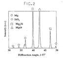
- magnesium powder (average particle diameter : 110 ⁇ m) and silica powder (average particle diameter : 21 ⁇ m) were prepared and both were mixed so as to comprise 38% by weight of the silica powder.
- the mixed powder was pressed and molded at a pressure of 600MPa, the molded body was processed by a vacuum heating treatment, that was, it was held at the heating temperature of 530°C for 10 minutes and then the composite material X-1 was provided.
- Fig. 1 shows a XRD result of the mixed powder before the heating treatment and (b) shows a XRD result of the sample powder (composite material X-1) after the vacuum heating treatment.
- a shows a XRD result of the mixed powder before the heating treatment
- b shows a XRD result of the sample powder (composite material X-1) after the vacuum heating treatment.
- diffraction peaks of Mg and SiO 2 which constitute the raw material of the mixed powder are detected.
- diffraction peaks of Mg 2 Si and MgO are observed in the sample powder after the vacuum heating treatment.
- the oxidation-reduction reaction shown in the above formula (I) developed while heated and held at 530°C, and Mg 2 Si and MgO were synthesized.
- a pressed magnesium powder body comprising only magnesium was previously prepared.
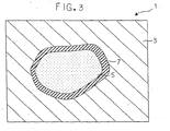
- Silica powder (particle diameter: about 183 ⁇ m) was embedded in the pressed powder body and processed by the vacuum heating treatment, that was, it was held at 530°C for 10 minutes. Thus, a sample X-2 was provided.
- sample X-2, and especially unreacted SiO 2 remaining in the sample X-2 were examined by EDX surface microanalysis (Energy Dispersive X-ray spectroscopy) (components Si, Mg and O were examined, respectively).
- the result was photographed by a scanning electron microscope.
- the photograph taken by the scanning electron microscope was schematically shown in Fig. 3.
- reference numeral 1 designates a schematic view showing a photograph taken by the scanning electron microscope.
- Mg was detected in a part shown by 3
- Si and O were detected but Mg was not detected in a part shown by 5 in which SiO 2 particles seem to exist.
- Si, O and Mg were detected in a part shown by 7.
- the magnesium base composite material in which unreacted SiO 2 is dispersed in addition to Mg 2 Si and MgO generated by synthesis reaction can be designed by controlling the particle diameter of the first material and/or the second material, for example controlling the particle diameter of SiO 2 of the second material.
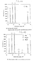
- Fig. 4A is a result of the X-ray diffraction for the mixed powder before the heating treatment
- Fig. 4B shows the result of the X-ray diffraction for the sample X-3 in which the vacuum heating treatment was performed.
- the silica glass is amorphous, its diffraction peak is not detected but only peaks of the other material Mg are detected in the mixed powder as shown in Fig. 4A.
- diffraction peaks of Mg 2 Si and MgO are detected in addition to diffraction peaks of the raw material of Mg after the heating treatment as show in Fig. 4B.
- the magnesium base composite material in which Mg 2 Si and MgO are dispersed can be manufactured.
- the magnesium base composite material of the present invention and the magnesium base composite material manufactured by the method of the present invention have high hardness, high corrosion resistance, and excellent abrasion resistance as well as being light, and furthermore, they have tempered opponent aggression. Consequently, they can be applied to a structural component material such as car components or household electric appliances in which the above characteristics are required at the same time, for example.
- pure Mg powder (average particle diameter: 165 ⁇ m) and silica powder (average particle diameter : 58 ⁇ m) were prepared, and both were combined so as to comprise the silica powder at a ratio (% by weight) shown in a table 1 in 100% by weight of the mixture and uniformly mixed by a ball mill.
- a circular mold which is 34mm in diameter was filled with the provided mixed powder and a surface pressure of 6t/cm 2 was applied to it.
- pressed powder molded bodies A-1 to A-7 were manufactured.
- a tubular furnace as would be described below was prepared. That was, the tubular furnace was filled with nitrogen gas (gas flow rate: 3dm 3 /min) and a temperature in the furnace was controlled at 480°C.
- the pressed powder molded bodies A-1 to A-7 were put in the tubular furnace and heated up and held for 10 minutes. Then, they were taken out of the furnace and immediately solidified to have a relative density of 99% or more by a powder forging method and solid bodies, that was, magnesium base composite materials B-1 to B-7 were provided.
- the conditions of the powder forging method was such that a mold temperature was 250°C and the surface pressure was 8t/cm 2 and a water-soluble lubricating agent was added to a wall surface of the mold in view of prevention of adhesion between the solidified body and the mold.
- the magnesium base composite materials B-1 to B-7 were examined by the X-ray diffraction whether Mg 2 Si and MgO were generated and also the content of Mg 2 Si and MgO were found.
- the result of measured tensile strength and hardness HRE (Rockwell hardness/E scale) are also shown in the table 1 together with the above result.
- the composite materials B-1 and B-7 comprised Mg only other than Mg 2 Si and MgO.
- test sample a test specimen (diameter : ⁇ 3.5mm and parallel part : 14mm) was prepared.
- the tensile test was performed such that the test specimen was mounted on a 10 ton autograph and a tensile load was applied at a displacement speed of 0.5mm/minute. A value provided such that the load when the test specimen was broken was divided by a break area was regarded as the tensile strength.
- Table 1 Characteristics of pressed powder molded bodies A-1 to A-7 and composite materials B-1 to B-7 Run No.
- Mg 2 Si and MgO are generated by reaction of the Mg powder and the silica powder at the heating step in the pressed powder molded bodies A-1 to A-4, that is, the composite materials B-1 to B-4.
- the magnesium base composite materials have favorable mechanical characteristics and machinability because the contents of Mg 2 Si and MgO dispersed in the composite materials are in an appropriate range.
- the pressed powder molded body A-5 that is, the composite material B-5
- the contents of Mg 2 Si and MgO exceed the appropriate range
- the pressed powder molded bodies A-6 and A-7 that is, the composite materials B-6 and B-7
- the contents of Mg 2 Si and MgO are lower than the appropriate range
- the pressed powder molded body A-7 that is, the composite material B-7
- adhesion to a tool during mechanical processing is considerably increased and its machinability is lowered.
- pure Mg powder (average particle diameter : 112 ⁇ m), AZ91D magnesium alloy powder (average diameter : 61 ⁇ m, nominal composition : Mg-9A1-1Zn/mass%) and silica powder (average particle diameter : 24 ⁇ m) were prepared.
- the pure Mg powder and the silica powder were combined and the Mg alloy powder and the silica powder were combined so as to comprise 8% by weight of the silica powder based on 100% by weight of the mixture. Then, they are uniformly mixed using a ball mill and mixed powder was provided. Then, a circular mold which is 11mm in diameter is filled with the provided mixed powder and a surface pressure of 8t/cm 2 was applied to it.
- pressed powder molded bodies A-8 to A-17 were manufactured.
- a tubular furnace as would be described below was prepared. That was, the tubular furnace was filled with nitrogen gas (gas flow rate : 3dm 3 /min) and a temperature in the furnace was controlled at values shown in a table 2.
- the pressed powder molded bodies A-8 to A-17 were put in the tubular furnace and heated up and held for 30 minutes. Then, they were cooled down to a room temperature in the furnace containing the nitrogen gas and taken out of the furnace.
- magnesium group composite materials B-8 to B-17 were provided. They were examined by the X-ray diffraction whether Mg 2 Si and MgO were generated and whether unreacted SiO 2 remained or not. The results are shown in the table 2.
- composite materials B-8 to B-12 comprised Mg only other than components shown in the table 2.
- composite materials B13 to B-15 and B-17 comprised components of the Mg alloy, that was, Mg, Al and Zn other than components shown in the table 2.
- Table 2 Characteristics of pressed powder molded bodies A-8 to A-17 and composite materials B-8 to B-17 Run No.
- the composite materials B-8 to B-15 which are the mixtures of the pure Mg powder and the silica powder and the mixtures of the Mg alloy powder and the silica powder
- Mg 2 Si and MgO are generated by a reaction of the pure Mg powder and the silica powder, or a reaction of the Mg alloy powder and the silica powder at the heating process under appropriate heating and holding conditions.
- pure Mg powder (average particle diameter : 112 ⁇ m) and silica glass powder (average particle diameter : 45 ⁇ m) were prepared. They were combined so as to comprise 5% by weight of the silica glass powder based on 100% by weight of the mixed powder. Then, the mixture were uniformly mixed using a ball mill. Then, a circular mold which is 11mm in diameter is filled with the provided mixed powder and a surface pressure of 8t/cm 2 was applied to it and pressed powder molded bodies A-18 to A-24 were manufactured.
- a tubular furnace as would be described below was prepared. That was, the tubular furnace was filled with nitrogen gas (gas flow rate : 3dm 3 /min) and a temperature in the furnace was controlled at values shown in a table 3.
- the pressed powder molded bodies A-18 to A-24 were put in the tubular furnace and heated up and held for 30 minutes. Then, they were cooled down to a room temperature in the furnace containing the nitrogen gas and taken out of the furnace.
- magnesium group composite materials B-18 to B-24 were provided. They were also examined by the X-ray diffraction whether Mg 2 Si and MgO were generated. The results are shown in the table 3.
- the composite materials B-18 to B-24 comprised Mg only other than components of Mg 2 Si and MgO shown in the table 3.
- Table 3 Characteristics of pressed powder molded bodies A-18 to A-24 and composite materials B-18 to B-24 Run No. Pressed powder molded body Heating temperature (°C)
- Mg 2 Si and MgO are generated by a reaction of the pure Mg powder and the silica glass powder at the heating process in the pressed powder molded bodies of the pure Mg powder and the silica glass powder under appropriate heating and holding conditions.
- pure Mg powder (average particle diameter : 165 ⁇ m), silica powder (average particle diameter : 58 ⁇ m) and Si powder (average particle diameter: 165 ⁇ m) were prepared.
- pressed powder molded bodies A-(a) to A-(c) and magnesium base composite materials B-(a) to B-(c) were provided by the following methods (a) to (c).
- Method (a) the pure Mg powder and the silica powder were combined so as to comprise 4.5% by weight of the silica powder based on 100% by weight of the mixture and they were uniformly mixed by a ball mill.
- Method (b) the pure Mg powder and the Si powder were combined so as to comprise 2% by weight of the Si powder based on 100% by weight of the mixture and they were uniformly mixed by the ball mill.
- Method (c) the pure Mg powder and the Si powder were combined so as to comprise 4% by weight of the Si powder based on 100% by weight of the mixture and they were uniformly mixed by the ball mill.
- a circular mold which is 34mm in diameter is filled with the provided mixed powder and a surface pressure of 7t/cm 2 was applied to it.
- the pressed powder molded bodies A-(a) to A-(c) were manufactured.
- a tubular furnace as would be described below was prepared. That was, the tubular furnace was filled with nitrogen gas (gas flow rate : 3dm 3 /min) and a temperature in the furnace was controlled at 500°C.
- the pressed powder molded bodies A-(a) to A-(c) were put in the tubular furnace and heated up and held for 10 minutes. Then, they are taken out of the furnace and immediately solidified to have a relative density of 99% or more by a powder forging method and the solidified bodies, that was, the magnesium group composite materials B-(a) to B-(c) were provided.
- the conditions of the powder forging method was such that a mold temperature was 250 °C and the surface pressure was 8t/cm 2 and a water-soluble lubricating agent was added to a wall surface of the mold in view of prevention of adhesion between the solid body and the mold.
- the content of Mg 2 Si was 5.5% by weight and that of MgO was 5.8% by weight based on 100% by weight of the composite material B-(a). In addition, the balance was only Mg.
- Mg 2 Si was 5.3% by weight based on 100% by weight of the composite material B-(b)
- MgO could not be detected.
- the balance was Mg only.
- Mg 2 Si was 11.2% by weight based on 100% by weight of the composite material B-(c)
- MgO could not be detected.
- the results are shown in a table 4.
- the balance was Mg only.
- Pin-shaped abrasion test specimens 13 which were 7mm in diameter were taken from the composite materials B-(a) to B-(c).
- a disc-shaped test specimen comprising AZ91D magnesium alloy was used as an opponent material.
- the testing conditions are such that pressure force : 50kg, a sliding speed: 1m/sec, and a test time : 30 minutes, and the abrasion test was performed with the test specimens 13 and 15 soaked in a lubricating oil (engine oil) 15 under wet circumstances.
- the maximum height Rmax in the sliding surface of each sample after the test was measured by a surface-roughness measuring device (surface-roughness measuring device using a stylus method) according to JIS B 0651 : 1996. The results are shown in a table 4.
- Rmax means a maximum height in a part in which a distance of a reference length L is removed in a sectional curve and designated by the micrometer ( ⁇ m). However, the measurement was made by removing the reference length only from a part in which there was no extremely high or deep part which appeared to be a flaw.
- the surface roughness Rmax in the sliding surface of the pin-shaped and disc-shaped abrasion test specimens before the test was 1.5 to 2.
- Table 4 Characteristics of pressed powder molded bodies A-(a) to A-(c) and composite materials B-(a) to B-(c) Run No. Pressed powder molded body Composite material Formed content (% by weight) Rmax of surface roughness after abrasion test Mg 2 Si MgO Pin-shaped test specimen Disc-shaped test specimen (a) A ⁇ (a) B ⁇ (a) 5.5 5.8 8.8 11.2 (b) A ⁇ (b) B ⁇ (b) 5.3 0 12.3 26.5 (c) A ⁇ (c) B ⁇ (c) 11.2 0 7.2 39.4
- the surface roughness itself that is, the value of the surface roughness of the pin-shaped abrasion test specimen is small as compared with that of the composite material B-(b) containing almost the same amount of Mg 2 Si.
- the surface roughness of the opponent material that is, the surface roughness of the disc-shaped abrasion test specimen is also small which is half or less of that of the composite material B-(b). This shows that since the composite material B-(a) contains MgO as well as Mg 2 Si, the opponent aggression is considerably improved.
- the composite material B-(a) is compared with the composite material B-(c), the following is understood. That is, it is shown that when the content of Mg 2 Si in the composite material is large, the abrasion resistance of the composite material itself is improved in some degree. That is, it can be seen that the value of the surface roughness of the pin-shaped abrasion test specimen of the composite material B-(c) in which the content of Mg 2 Si is large, becomes small. However, the surface roughness of the sliding surface of the opponent material (the surface roughness of the disc-shaped abrasion test specimen) in the composite material B-(c) is three times or more as large as that of the composite material B-(a). Therefore, it is found that the composite material B-(a) retains almost the same degree of abrasion resistance as that of the composite material B-(c), while its opponent aggression is improved.
- a column-shaped pressed powder solidified body having a diameter of 40mm was manufactured from each mixture powder and after each solidified body was heated up and held at 550°C for 5 minutes in a tubular furnace which was filled with nitrogen gas, warm extrusion processing was immediately performed at an extrusion ratio of 25 to provide an extruded bar having a diameter of 8mm.
- Mg 2 Si particles were generated by a solid-phase reaction.
- a pin-shaped abrasion test specimen (its diameter : 7.8mm) was obtained from the extruded bar.
- S35C steel was used as the disc material of the opponent and conditions were such that a pressing load was 500N, a sliding speed was 1m/s and a testing time was 30 minutes in a row.
- the test was performed under wet lubricating conditions in which an engine lubricating oil (10W30) was dropped from the upper part of the pin-shaped test specimen such that the lubricating oil always existed on a sliding surface between the pin-shaped test specimen and the disc-shaped test specimen.
- the coefficients of friction calculated from measured friction torques are shown in the table 5.
Landscapes
- Chemical & Material Sciences (AREA)
- Engineering & Computer Science (AREA)
- Mechanical Engineering (AREA)
- Materials Engineering (AREA)
- Metallurgy (AREA)
- Organic Chemistry (AREA)
- General Engineering & Computer Science (AREA)
- Inorganic Chemistry (AREA)
- Powder Metallurgy (AREA)
- Manufacture Of Alloys Or Alloy Compounds (AREA)
Claims (15)
- Strukturkomponentenwerkstoff umfassend einen Verbundwerkstoff auf Magnesiumbasis, in dem Teilchen, die durch eine Festphasenreaktion mit Magnesium erzeugt werden, gleichmäßig in einem Magnesiumlegierungskörper dispergiert sind, wobei die Verbindungsteilchen Magnesiumsilizid (Mg2Si) und Magnesiumoxid (MgO) aufweisen, das durch eine Festphasenreaktionssinterung zwischen Magnesium (Mg) und Siliziumdioxid (SiO2) in einem gepressten Pulvergusskörper während der Aufheizung erzeugt wird, gekennzeichnet dadurch, dass es 3 bis 15 Gewichtsteile des Magnesiumsilizids (Mg2Si) und 3 oder mehr Gewichtsteile des Magnesiumoxids (MgO) bezogen auf 100 Gewichtsprozent des Verbundmaterials der Magnesiumgruppe aufweist.
- Strukturkomponentenmaterial umfassend ein Verbundmaterial auf Magnesiumbasis gemäß Anspruch 1, worin die Verbindungsteilchen ferner eine SiO2-Komponente umfassen.
- Strukturkomponentenmaterial umfassend ein Verbundmaterial auf Magnesiumbasis gemäß Anspruch 1, umfassend 5 bis 8 Gewichtsteile des Magnesiumsilizids.
- Strukturkomponentenmaterial umfassend ein Verbundmaterial auf Magnesiumbasis gemäß Anspruch 1, umfassend 3 bis 15 Gewichtsteile des Magnesiumoxids bezogen auf 100 Gewichtsteile des Verbundmaterials auf Magnesiumbasis.
- Strukturkomponentenmaterial umfassend ein Verbundmaterial auf Magnesiumbasis gemäß Anspruch 4, umfassend 5 bis 8 Gewichtsteile des Magnesiumoxids.
- Strukturkomponentenmaterial umfassend ein Verbundmaterial auf Magnesiumbasis gemäß Anspruch 1, worin das Verbundmaterial auf Magnesiumbasis ein Graphitpulver als Festkörper-Schmiermittel aufweist, und ein Graphitpulvergehalt 0,5 bis 3 Gewichtsprozent in dem Verbundmaterial auf Magnesiumbasis beträgt.
- Verfahren zur Herstellung eines Strukturkomponentenmaterials, das ein Verbundmaterial auf Magnesiumbasis aufweist, umfassend:einen Schritt, der Bereitstellung einer Mischung durch Mischen eines ersten Magnesium enthaltenden Materials und eines zweiten eine SiO2-Komponente enthaltenden Materials, so dass sie 2,5 bis 12 Gewichtsteile der SiO2-Komponente bezogen auf 100 Gewichtsprozent der Gesamtmenge der ersten und zweiten Materialien umfasst;einen Schritt der Bereitstellung eines gepressten Pulvergusskörpers durch Aufbringen eines Drucks auf die Mischung; undeinen Schritt des Aufheizens des gepressten Pulvergusskörpers auf 250° C oder mehr in einer Inertgasatmosphäre oder einem Vakuum, um Magnesiumsilizid (Mg2Si) und Magnesiumoxid (MgO) in einem Magnesiumlegierungskörper durch eine Festphasenreaktionssinterung zwischen Mg und SiO2 in dem gepressten Pulvergusskörper zu erzeugen.
- Verfahren zur Herstellung eines Strukturkomponentenmaterials, das ein Verbundmaterial auf Magnesiumbasis aufweist, nach Anspruch 7, worin das Verbundmaterial auf Magnesiumbasis ferner SiO2 aufweist, und worin das Si02 gleichförmig in dem Verbundmaterial auf Magnesiumbasis dispergiert ist.
- Verfahren zur Herstellung eines Strukturkomponentenmaterials, das ein Verbundmaterial auf Magnesiumbasis aufweist, nach Anspruch 7, worin 3 oder mehr Gewichtsteile Mg2Si in 100 Gewichtsteilen des Verbundmaterials auf Magnesiumbasis enthalten ist.
- Verfahren zur Herstellung eines Strukturkomponentenmaterials, das ein Verbundmaterial auf Magnesiumbasis aufweist, nach Anspruch 7, wobei 3 oder mehr Gewichtsprozent des MgO in 100 Gewichtsprozent des Verbundmaterials auf Magnesiumbasis enthalten ist.
- Verfahren zur Herstellung eines Strukturkomponentenmaterials, das ein Verbundmaterial auf Magnesiumbasis aufweist, nach Anspruch 7, ferner umfassend einen Schritt des Mahlens der Mischung vor dem Schritt des Bereitstellens des gepressten Pulvergusskörpers.
- Verfahren zur Herstellung eines Strukturkomponentenmaterials, das ein Verbundmaterial auf Magnesiumbasis aufweist, nach Anspruch 11, umfassend einen Schritt der Druckzusammenfügung der Mischung nach dem Schritt des Zermahlens der Mischung.
- Verfahren zur Herstellung eines Strukturkomponentenmaterials, das ein Verbundmaterial auf Magnesiumbasis aufweist, nach Anspruch 12, umfassend einen Schritt der Zerkleinerung der Mischung nach dem Schritt der Druckzusammenfügung der Mischung.
- Verfahren zur Herstellung eines Strukturkomponentenmaterials, das ein Verbundmaterial auf Magnesiumbasis aufweist, nach Anspruch 7, worin eine Heiztemperatur des gepressten Pulvergusskörpers 250° C oder mehr und nicht mehr als ein Schmelzpunkt des Magnesiums beträgt.
- Verfahren zur Herstellung eines Strukturkomponentenmaterials, das ein Verbundmaterial auf Magnesiumbasis aufweist, nach Anspruch 6, ferner umfassend einen Schritt der Ausbildung einer neuen Phase in dem Magnesium in dem ersten Material durch Zermahlen und/oder Druckverbinden und/oder Zerkleinern der Mischung vor dem Schritt der Bereitstellung des gepressten Pulvergusskörpers.
Applications Claiming Priority (3)
| Application Number | Priority Date | Filing Date | Title |
|---|---|---|---|
| JP2002037983 | 2002-02-15 | ||
| JP2002037983 | 2002-02-15 | ||
| PCT/JP2003/001612 WO2003069001A1 (en) | 2002-02-15 | 2003-02-14 | Magnesium base composite material and method for production thereof |
Publications (3)
| Publication Number | Publication Date |
|---|---|
| EP1477576A1 EP1477576A1 (de) | 2004-11-17 |
| EP1477576A4 EP1477576A4 (de) | 2005-07-13 |
| EP1477576B1 true EP1477576B1 (de) | 2007-04-18 |
Family
ID=27678144
Family Applications (1)
| Application Number | Title | Priority Date | Filing Date |
|---|---|---|---|
| EP03705207A Expired - Lifetime EP1477576B1 (de) | 2002-02-15 | 2003-02-14 | Verbundwerkstoff auf magnesiumbasis und herstellungsverfahren dafür |
Country Status (8)
| Country | Link |
|---|---|
| US (1) | US7052526B2 (de) |
| EP (1) | EP1477576B1 (de) |
| JP (1) | JP4215126B2 (de) |
| CN (1) | CN1291048C (de) |
| AT (1) | ATE360101T1 (de) |
| AU (1) | AU2003211224A1 (de) |
| DE (1) | DE60313294T2 (de) |
| WO (1) | WO2003069001A1 (de) |
Families Citing this family (18)
| Publication number | Priority date | Publication date | Assignee | Title |
|---|---|---|---|---|
| US20060057015A1 (en) * | 2003-01-08 | 2006-03-16 | Katsuyoshi Kondoh | Magnesium composite powder, method for producing same, magnesium base composite material and method for producing same |
| DE10352453A1 (de) * | 2003-11-07 | 2005-06-02 | Volkswagen Ag | Verfahren zur Herstellung von Metall-Matrix-Verbundwerkstoffen |
| JP4947690B2 (ja) * | 2006-05-18 | 2012-06-06 | 株式会社大阪チタニウムテクノロジーズ | チタン系合金球状粉末の製造方法 |
| CN101306818B (zh) * | 2008-07-01 | 2010-06-09 | 浙江理工大学 | 一种硅化镁的制备方法与装置 |
| CN101643861B (zh) * | 2009-09-01 | 2011-07-20 | 河南理工大学 | Mg-Si二元合金制备方法 |
| JP5598792B2 (ja) * | 2010-05-28 | 2014-10-01 | 株式会社三徳 | マグネシウム−シリコン系熱電変換材料およびその製造方法 |
| JP5641474B2 (ja) * | 2010-11-08 | 2014-12-17 | 日立化成株式会社 | Mg2Si基化合物から成る熱電材料の製造方法 |
| CN102417999B (zh) * | 2011-12-09 | 2013-06-12 | 中国科学院长春应用化学研究所 | 一种镁合金的制备方法 |
| CN104261411B (zh) * | 2014-09-22 | 2017-01-18 | 江苏大学 | 一种类石墨烯状硅化镁纳米片的制备方法 |
| CN104556040A (zh) * | 2014-12-03 | 2015-04-29 | 江苏大学 | 一种无定形单质硅球及其制备方法和用途 |
| JP6798339B2 (ja) * | 2016-02-24 | 2020-12-09 | 三菱マテリアル株式会社 | マグネシウム系熱電変換材料の製造方法、マグネシウム系熱電変換素子の製造方法、マグネシウム系熱電変換材料、マグネシウム系熱電変換素子、熱電変換装置 |
| JP6981094B2 (ja) * | 2017-08-15 | 2021-12-15 | 三菱マテリアル株式会社 | マグネシウム系熱電変換材料、マグネシウム系熱電変換素子、及び、マグネシウム系熱電変換材料の製造方法 |
| JP7266269B2 (ja) * | 2018-01-31 | 2023-04-28 | 国立研究開発法人物質・材料研究機構 | Mg基焼結複合材とその製造方法および摺動部材 |
| CN110106412B (zh) * | 2019-06-14 | 2020-05-22 | 天津理工大学 | 原位自生MgO增强Mg-Zn-Ca合金的制备方法及其应用 |
| JP7683275B2 (ja) * | 2021-03-30 | 2025-05-27 | セイコーエプソン株式会社 | チクソ成形用材料、チクソ成形用材料の製造方法およびチクソ成形体 |
| CN115874125B (zh) * | 2021-09-28 | 2023-12-19 | 宝钢金属有限公司 | 一种镁合金表面改性方法 |
| JP2023097684A (ja) | 2021-12-28 | 2023-07-10 | セイコーエプソン株式会社 | チクソ成形用材料およびチクソ成形用材料の製造方法 |
| CN119674033B (zh) * | 2024-12-24 | 2025-12-09 | 上海杉杉新材料有限公司 | 镁基复合材料、预镁氧化亚硅材料及其制备方法、应用及锂离子电池 |
Family Cites Families (11)
| Publication number | Priority date | Publication date | Assignee | Title |
|---|---|---|---|---|
| US3119725A (en) * | 1961-11-27 | 1964-01-28 | Dow Chemical Co | Die-expressed article of magnesium-base alloy and method of making |
| US3119684A (en) * | 1961-11-27 | 1964-01-28 | Dow Chemical Co | Article of magnesium-base alloy and method of making |
| JPS5747843A (en) * | 1980-09-05 | 1982-03-18 | Nissan Motor Co Ltd | Damping composite magnesium material with high strength and wear resistance |
| JPH0684526B2 (ja) * | 1986-08-08 | 1994-10-26 | トヨタ自動車株式会社 | 摺動用部材 |
| US5273569A (en) * | 1989-11-09 | 1993-12-28 | Allied-Signal Inc. | Magnesium based metal matrix composites produced from rapidly solidified alloys |
| JPH0681068A (ja) | 1992-09-01 | 1994-03-22 | Honda Motor Co Ltd | 耐熱Mg合金の鋳造方法 |
| JPH07310131A (ja) * | 1994-03-24 | 1995-11-28 | Suzuki Motor Corp | Mg基複合材料の製造方法 |
| JPH0841564A (ja) | 1994-08-01 | 1996-02-13 | Suzuki Motor Corp | Mg基複合材と、その製造方法 |
| US5791397A (en) * | 1995-09-22 | 1998-08-11 | Suzuki Motor Corporation | Processes for producing Mg-based composite materials |
| JP4352472B2 (ja) | 1998-06-26 | 2009-10-28 | 株式会社豊田中央研究所 | マグネシウム基複合材料 |
| JP2001047298A (ja) * | 1999-06-03 | 2001-02-20 | Hideo Suzuki | 塑性加工装置の高速運動部品 |
-
2003
- 2003-02-14 CN CN03803825.0A patent/CN1291048C/zh not_active Expired - Fee Related
- 2003-02-14 JP JP2003568111A patent/JP4215126B2/ja not_active Expired - Fee Related
- 2003-02-14 DE DE60313294T patent/DE60313294T2/de not_active Expired - Lifetime
- 2003-02-14 AU AU2003211224A patent/AU2003211224A1/en not_active Abandoned
- 2003-02-14 US US10/503,730 patent/US7052526B2/en not_active Expired - Fee Related
- 2003-02-14 AT AT03705207T patent/ATE360101T1/de not_active IP Right Cessation
- 2003-02-14 EP EP03705207A patent/EP1477576B1/de not_active Expired - Lifetime
- 2003-02-14 WO PCT/JP2003/001612 patent/WO2003069001A1/ja not_active Ceased
Also Published As
| Publication number | Publication date |
|---|---|
| WO2003069001A1 (en) | 2003-08-21 |
| AU2003211224A1 (en) | 2003-09-04 |
| US7052526B2 (en) | 2006-05-30 |
| ATE360101T1 (de) | 2007-05-15 |
| JPWO2003069001A1 (ja) | 2005-06-02 |
| DE60313294D1 (de) | 2007-05-31 |
| CN1633512A (zh) | 2005-06-29 |
| EP1477576A1 (de) | 2004-11-17 |
| DE60313294T2 (de) | 2008-03-06 |
| JP4215126B2 (ja) | 2009-01-28 |
| EP1477576A4 (de) | 2005-07-13 |
| US20050089435A1 (en) | 2005-04-28 |
| CN1291048C (zh) | 2006-12-20 |
Similar Documents
| Publication | Publication Date | Title |
|---|---|---|
| EP1477576B1 (de) | Verbundwerkstoff auf magnesiumbasis und herstellungsverfahren dafür | |
| JP6257896B2 (ja) | 高靭性マトリックス材料中の固結された高靭性被覆硬質粒子 | |
| IL173056A (en) | Method for the production of fine metal powder, alloy powder and composite powder | |
| WO2010002832A2 (en) | Abrasive slicing tool for electronics industry | |
| CA2585437A1 (en) | Cubic boron nitride compact | |
| EP1948837A2 (de) | Kubisches bornitrid enthaltender presskörper | |
| Radhika et al. | Mechanical and tribological properties of functionally graded aluminium/zirconia metal matrix composite synthesized by centrifugal casting | |
| JPS627149B2 (de) | ||
| US20060057015A1 (en) | Magnesium composite powder, method for producing same, magnesium base composite material and method for producing same | |
| EP1772213A1 (de) | Verbundpulver auf magnesiumgrundlage, legierungsmaterial auf magnesiumgrundlage und verfahren für seine herstellung | |
| Venkatesh et al. | Hybrid filler actions on functional performance evaluation of magnesium alloy (AZ61) hybrid nanocomposites | |
| JP6342916B2 (ja) | Al/TiCナノコンポジット材料を製造する方法 | |
| US20200377975A1 (en) | Particle-reinforced aluminum composite material, pressure-resistant component using same, and method for manufacturing pressure-resistant component | |
| WO2003027341A1 (en) | Magnesium base composite material | |
| JP7266269B2 (ja) | Mg基焼結複合材とその製造方法および摺動部材 | |
| CN118253769A (zh) | 触变成型用材料、触变成型用材料的制造方法以及触变成型体 | |
| WO2021200868A1 (ja) | 窒化ケイ素粉末、及び窒化ケイ素焼結体の製造方法 | |
| Omole et al. | SOLUTIONIZATION OF ALUMINIUM 6063 MATRIX WITH 5% HDPE FOR IMPROVED HARDNESS AND TENSILE PROPERTIES | |
| CN103160716B (zh) | 低热膨胀和高强度AlN-Si-Al混杂复合材料及其制备方法 | |
| García de Cortazar et al. | Titanium composite materials for transportation applications | |
| KR102124566B1 (ko) | 고경도 cBN 소결체의 제조방법 | |
| JPH07207302A (ja) | AlN分散型アルミニウム合金複合材料の製造方法 | |
| Mintzer et al. | Microstructure of aluminium-alumina-silica participate composites obtained by reactive sintering | |
| Zeer et al. | Effect of the Addition of Cu and Al on the Microstructure, Phase Composition and Properties of a Ti-6Al-4V Alloy Obtained by Selective Laser Melting. | |
| Ahmad et al. | Physico-Mechanical Properties of Sintered Iron-Silica Sand Nanoparticle Composites: A Preliminary Study |
Legal Events
| Date | Code | Title | Description |
|---|---|---|---|
| PUAI | Public reference made under article 153(3) epc to a published international application that has entered the european phase |
Free format text: ORIGINAL CODE: 0009012 |
|
| 17P | Request for examination filed |
Effective date: 20040909 |
|
| AK | Designated contracting states |
Kind code of ref document: A1 Designated state(s): AT BE BG CH CY CZ DE DK EE ES FI FR GB GR HU IE IT LI LU MC NL PT SE SI SK TR |
|
| AX | Request for extension of the european patent |
Extension state: AL LT LV MK RO |
|
| A4 | Supplementary search report drawn up and despatched |
Effective date: 20050531 |
|
| GRAP | Despatch of communication of intention to grant a patent |
Free format text: ORIGINAL CODE: EPIDOSNIGR1 |
|
| GRAS | Grant fee paid |
Free format text: ORIGINAL CODE: EPIDOSNIGR3 |
|
| GRAA | (expected) grant |
Free format text: ORIGINAL CODE: 0009210 |
|
| AK | Designated contracting states |
Kind code of ref document: B1 Designated state(s): AT BE BG CH CY CZ DE DK EE ES FI FR GB GR HU IE IT LI LU MC NL PT SE SI SK TR |
|
| PG25 | Lapsed in a contracting state [announced via postgrant information from national office to epo] |
Ref country code: FI Free format text: LAPSE BECAUSE OF FAILURE TO SUBMIT A TRANSLATION OF THE DESCRIPTION OR TO PAY THE FEE WITHIN THE PRESCRIBED TIME-LIMIT Effective date: 20070418 Ref country code: CH Free format text: LAPSE BECAUSE OF FAILURE TO SUBMIT A TRANSLATION OF THE DESCRIPTION OR TO PAY THE FEE WITHIN THE PRESCRIBED TIME-LIMIT Effective date: 20070418 Ref country code: LI Free format text: LAPSE BECAUSE OF FAILURE TO SUBMIT A TRANSLATION OF THE DESCRIPTION OR TO PAY THE FEE WITHIN THE PRESCRIBED TIME-LIMIT Effective date: 20070418 Ref country code: SI Free format text: LAPSE BECAUSE OF FAILURE TO SUBMIT A TRANSLATION OF THE DESCRIPTION OR TO PAY THE FEE WITHIN THE PRESCRIBED TIME-LIMIT Effective date: 20070418 |
|
| REG | Reference to a national code |
Ref country code: CH Ref legal event code: EP |
|
| REG | Reference to a national code |
Ref country code: IE Ref legal event code: FG4D |
|
| REF | Corresponds to: |
Ref document number: 60313294 Country of ref document: DE Date of ref document: 20070531 Kind code of ref document: P |
|
| PG25 | Lapsed in a contracting state [announced via postgrant information from national office to epo] |
Ref country code: SE Free format text: LAPSE BECAUSE OF FAILURE TO SUBMIT A TRANSLATION OF THE DESCRIPTION OR TO PAY THE FEE WITHIN THE PRESCRIBED TIME-LIMIT Effective date: 20070718 |
|
| PG25 | Lapsed in a contracting state [announced via postgrant information from national office to epo] |
Ref country code: ES Free format text: LAPSE BECAUSE OF FAILURE TO SUBMIT A TRANSLATION OF THE DESCRIPTION OR TO PAY THE FEE WITHIN THE PRESCRIBED TIME-LIMIT Effective date: 20070729 |
|
| PG25 | Lapsed in a contracting state [announced via postgrant information from national office to epo] |
Ref country code: PT Free format text: LAPSE BECAUSE OF FAILURE TO SUBMIT A TRANSLATION OF THE DESCRIPTION OR TO PAY THE FEE WITHIN THE PRESCRIBED TIME-LIMIT Effective date: 20070918 |
|
| REG | Reference to a national code |
Ref country code: CH Ref legal event code: PL |
|
| NLV1 | Nl: lapsed or annulled due to failure to fulfill the requirements of art. 29p and 29m of the patents act | ||
| PG25 | Lapsed in a contracting state [announced via postgrant information from national office to epo] |
Ref country code: AT Free format text: LAPSE BECAUSE OF FAILURE TO SUBMIT A TRANSLATION OF THE DESCRIPTION OR TO PAY THE FEE WITHIN THE PRESCRIBED TIME-LIMIT Effective date: 20070418 |
|
| EN | Fr: translation not filed | ||
| PG25 | Lapsed in a contracting state [announced via postgrant information from national office to epo] |
Ref country code: BE Free format text: LAPSE BECAUSE OF FAILURE TO SUBMIT A TRANSLATION OF THE DESCRIPTION OR TO PAY THE FEE WITHIN THE PRESCRIBED TIME-LIMIT Effective date: 20070418 |
|
| PG25 | Lapsed in a contracting state [announced via postgrant information from national office to epo] |
Ref country code: BG Free format text: LAPSE BECAUSE OF FAILURE TO SUBMIT A TRANSLATION OF THE DESCRIPTION OR TO PAY THE FEE WITHIN THE PRESCRIBED TIME-LIMIT Effective date: 20070718 Ref country code: DK Free format text: LAPSE BECAUSE OF FAILURE TO SUBMIT A TRANSLATION OF THE DESCRIPTION OR TO PAY THE FEE WITHIN THE PRESCRIBED TIME-LIMIT Effective date: 20070418 Ref country code: CZ Free format text: LAPSE BECAUSE OF FAILURE TO SUBMIT A TRANSLATION OF THE DESCRIPTION OR TO PAY THE FEE WITHIN THE PRESCRIBED TIME-LIMIT Effective date: 20070418 Ref country code: NL Free format text: LAPSE BECAUSE OF FAILURE TO SUBMIT A TRANSLATION OF THE DESCRIPTION OR TO PAY THE FEE WITHIN THE PRESCRIBED TIME-LIMIT Effective date: 20070418 |
|
| PLBE | No opposition filed within time limit |
Free format text: ORIGINAL CODE: 0009261 |
|
| STAA | Information on the status of an ep patent application or granted ep patent |
Free format text: STATUS: NO OPPOSITION FILED WITHIN TIME LIMIT |
|
| PG25 | Lapsed in a contracting state [announced via postgrant information from national office to epo] |
Ref country code: SK Free format text: LAPSE BECAUSE OF FAILURE TO SUBMIT A TRANSLATION OF THE DESCRIPTION OR TO PAY THE FEE WITHIN THE PRESCRIBED TIME-LIMIT Effective date: 20070418 |
|
| 26N | No opposition filed |
Effective date: 20080121 |
|
| PG25 | Lapsed in a contracting state [announced via postgrant information from national office to epo] |
Ref country code: GR Free format text: LAPSE BECAUSE OF FAILURE TO SUBMIT A TRANSLATION OF THE DESCRIPTION OR TO PAY THE FEE WITHIN THE PRESCRIBED TIME-LIMIT Effective date: 20070719 Ref country code: IT Free format text: LAPSE BECAUSE OF FAILURE TO SUBMIT A TRANSLATION OF THE DESCRIPTION OR TO PAY THE FEE WITHIN THE PRESCRIBED TIME-LIMIT Effective date: 20070418 Ref country code: FR Free format text: LAPSE BECAUSE OF FAILURE TO SUBMIT A TRANSLATION OF THE DESCRIPTION OR TO PAY THE FEE WITHIN THE PRESCRIBED TIME-LIMIT Effective date: 20071214 |
|
| PG25 | Lapsed in a contracting state [announced via postgrant information from national office to epo] |
Ref country code: MC Free format text: LAPSE BECAUSE OF NON-PAYMENT OF DUE FEES Effective date: 20080228 |
|
| PG25 | Lapsed in a contracting state [announced via postgrant information from national office to epo] |
Ref country code: FR Free format text: LAPSE BECAUSE OF FAILURE TO SUBMIT A TRANSLATION OF THE DESCRIPTION OR TO PAY THE FEE WITHIN THE PRESCRIBED TIME-LIMIT Effective date: 20070418 |
|
| PG25 | Lapsed in a contracting state [announced via postgrant information from national office to epo] |
Ref country code: IE Free format text: LAPSE BECAUSE OF NON-PAYMENT OF DUE FEES Effective date: 20080214 Ref country code: EE Free format text: LAPSE BECAUSE OF FAILURE TO SUBMIT A TRANSLATION OF THE DESCRIPTION OR TO PAY THE FEE WITHIN THE PRESCRIBED TIME-LIMIT Effective date: 20070418 |
|
| PG25 | Lapsed in a contracting state [announced via postgrant information from national office to epo] |
Ref country code: CY Free format text: LAPSE BECAUSE OF FAILURE TO SUBMIT A TRANSLATION OF THE DESCRIPTION OR TO PAY THE FEE WITHIN THE PRESCRIBED TIME-LIMIT Effective date: 20070418 |
|
| PG25 | Lapsed in a contracting state [announced via postgrant information from national office to epo] |
Ref country code: HU Free format text: LAPSE BECAUSE OF FAILURE TO SUBMIT A TRANSLATION OF THE DESCRIPTION OR TO PAY THE FEE WITHIN THE PRESCRIBED TIME-LIMIT Effective date: 20071019 Ref country code: LU Free format text: LAPSE BECAUSE OF NON-PAYMENT OF DUE FEES Effective date: 20080214 |
|
| PG25 | Lapsed in a contracting state [announced via postgrant information from national office to epo] |
Ref country code: TR Free format text: LAPSE BECAUSE OF FAILURE TO SUBMIT A TRANSLATION OF THE DESCRIPTION OR TO PAY THE FEE WITHIN THE PRESCRIBED TIME-LIMIT Effective date: 20070418 |
|
| PGFP | Annual fee paid to national office [announced via postgrant information from national office to epo] |
Ref country code: GB Payment date: 20110221 Year of fee payment: 9 Ref country code: DE Payment date: 20110329 Year of fee payment: 9 |
|
| GBPC | Gb: european patent ceased through non-payment of renewal fee |
Effective date: 20120214 |
|
| REG | Reference to a national code |
Ref country code: DE Ref legal event code: R119 Ref document number: 60313294 Country of ref document: DE Effective date: 20120901 |
|
| PG25 | Lapsed in a contracting state [announced via postgrant information from national office to epo] |
Ref country code: GB Free format text: LAPSE BECAUSE OF NON-PAYMENT OF DUE FEES Effective date: 20120214 |
|
| PG25 | Lapsed in a contracting state [announced via postgrant information from national office to epo] |
Ref country code: DE Free format text: LAPSE BECAUSE OF NON-PAYMENT OF DUE FEES Effective date: 20120901 |