EP1476038B1 - Tige de chaussure et chaussure fabriquee avec cette tige, et procede de production y relatif - Google Patents
Tige de chaussure et chaussure fabriquee avec cette tige, et procede de production y relatif Download PDFInfo
- Publication number
- EP1476038B1 EP1476038B1 EP03704678A EP03704678A EP1476038B1 EP 1476038 B1 EP1476038 B1 EP 1476038B1 EP 03704678 A EP03704678 A EP 03704678A EP 03704678 A EP03704678 A EP 03704678A EP 1476038 B1 EP1476038 B1 EP 1476038B1
- Authority
- EP
- European Patent Office
- Prior art keywords
- connecting band
- end region
- lining
- longitudinal
- longitudinal side
- Prior art date
- Legal status (The legal status is an assumption and is not a legal conclusion. Google has not performed a legal analysis and makes no representation as to the accuracy of the status listed.)
- Expired - Lifetime
Links
Images


Classifications
-
- B—PERFORMING OPERATIONS; TRANSPORTING
- B29—WORKING OF PLASTICS; WORKING OF SUBSTANCES IN A PLASTIC STATE IN GENERAL
- B29D—PRODUCING PARTICULAR ARTICLES FROM PLASTICS OR FROM SUBSTANCES IN A PLASTIC STATE
- B29D35/00—Producing footwear
- B29D35/06—Producing footwear having soles or heels formed and joined on to preformed uppers using a moulding technique, e.g. by injection moulding, pressing and vulcanising
- B29D35/061—Producing footwear having soles or heels formed and joined on to preformed uppers using a moulding technique, e.g. by injection moulding, pressing and vulcanising by injection moulding
-
- A—HUMAN NECESSITIES
- A43—FOOTWEAR
- A43B—CHARACTERISTIC FEATURES OF FOOTWEAR; PARTS OF FOOTWEAR
- A43B7/00—Footwear with health or hygienic arrangements
- A43B7/12—Special watertight footwear
- A43B7/125—Special watertight footwear provided with a vapour permeable member, e.g. a membrane
-
- A—HUMAN NECESSITIES
- A43—FOOTWEAR
- A43B—CHARACTERISTIC FEATURES OF FOOTWEAR; PARTS OF FOOTWEAR
- A43B9/00—Footwear characterised by the assembling of the individual parts
- A43B9/02—Footwear stitched or nailed through
Definitions
- the invention relates to a shoe upper and thus constructed footwear, wherein the shaft is provided to achieve waterproofness with a waterproof and preferably also water vapor permeable functional layer and in addition the sole region of the footwear is sealed, and a method for producing such a shaft and such footwear.
- a shaft upper material is lined with a shaft lining material having a waterproof functional layer.
- the shaft upper is cut shorter at the sole end than the shaft lining material, so that a supernatant of the shaft lining material results over the upper shaft material.
- the supernatant is bridged by a mesh band, whose one longitudinal side with the sole side end of the upper upper material, but not with the shaft lining material, and the other longitudinal side with the sole side end of the shaft lining material, but not with the upper upper material, is sewn.
- the mesh band which preferably consists of monofilament fibers, interrupts a water bridge for water, which passes from the wetted shaft upper to the sole area.
- Footwear with a similar mesh tape solution is shown in the applicant's DE 199 38 139 A1, in which the area of the functional layer covered by the net band is not sealed by means of outsole material but by means of a reactive hotmelt adhesive which is applied to the outside of the net band in the as yet unreacted state and in the fully reacted state leads to water resistance.
- the shaft tends to wrinkles and distortions in the area of the net, especially at those points where the sole contour of the footwear has a narrow radius of curvature, especially in the toe and heel area, which is especially true for children's shoes .
- the net with its transverse dimension extends approximately perpendicularly to the outsole, wrinkling occurs because the lower end region of the shaft does not rise vertically from the outsole at most points of the upper end region circumference, but rather with skew, which is especially true for the toe region of shoes with a soft upper.
- the net band is in a region of the lower shaft end region folded over parallel to the outsole, wrinkling occurs due to different degrees of curvature of the edges of the upper material end region and Futtermaterialend Scheme.
- the invention has for its object to remedy this situation and to avoid the formation of wrinkles, even if the lower end of the functional layer extends to the edge of the mesh upper edge remote from the net.
- the invention makes a shoe upper specified in claim 1 type and footwear of the type specified in claim 25 available.
- the invention also provides a method for producing a shoe upper of the type specified in claim 36 and a method for the production of footwear of the kind specified in claim 55.
- An upper shoe upper comprises a upper upper material having a lower upper end region located in a lower shaft end region, a lower denim upper end having a waterproof functional layer disposed on the inner side of the upper material, the Futtermaterialend Scheme having a not covered by upper material sheath feed edge, and a circumferential in Schaftend Schemeswhosraum Connecting band, which is connected at a first longitudinal side with the Obermaterialend Scheme, but not with the Futtermaterialend Scheme, and at a second longitudinal side with the Futtermaterialend Scheme, but not with the Obermaterialend Scheme, wherein the connecting band at points of curvature of the lower Schaftend Schemes behaves corresponding to the local radius of curvature arcuate course having different strong curvature of the two connecting band longitudinal sides, such, d ass for a lying in the respective curvature arc sector with a given unit sector angle belonging to this arc sector arc lengths the curved length of the first connecting band longitudinal side is longer than the arc length of the second connecting band longitudinal side at points
- convex and concave means that the peripheral contour of the lower shaft end portion corresponding to the peripheral contour of the lower shaft end portion is bulged outwardly from the center of the later sole surface.
- Footwear according to the invention comprises such a shoe upper and a sealing material which watertightly seals the lining material end region in a sealing material zone situated in the area of the connecting band and circulating in the shaft end region circumferential direction.
- Wrinkling in the lining material and / or the upper requires thicker adhesive layers for gumming in the case of a shaved shaft and / or for gluing an outsole, and thus a higher sole construction than would be required without wrinkling. This also applies to molded-on soles, whose upstanding sole side edge has to be injected higher in the case of wrinkling.
- a connecting band which is adapted or adapted to different curvatures along the shaft end region circumference.
- a connecting band which is adapted or adapted to different curvatures along the shaft end region circumference.
- An elastically or plastically extensible band is suitable as an adaptable connection band, wherein adaptation to different curvatures is achievable by selecting a longitudinal expansion bias during connection to the feed material end region and / or the upper material end region.
- elastically stretchable connecting band is particularly easy and without design for a specific shoe model adapted to the different curvature conditions.
- the longitudinal side of the elastic connecting band connected to the lining material end region must be elastically stretchable and connected to the lining material end region under longitudinal expansion prestressing.
- the longitudinal side of the elastic connecting band connected to the Schaftobermaterialend Scheme need not, but may be elastically extensible and need not, but may be connected under longitudinal expansion bias to Schaftvormaterialend Scheme.
- both longitudinal sides of the elastic connecting band are bonded under longitudinal expansion bias, it is recommended that it is not absolutely necessary to join the longitudinal side joined to the lining material end portion under the same longitudinal stretch bias as the longitudinal side connected to the upper upper end portion.
- this elastic connecting band is connected at its longitudinal side connected to the shaft lining material under longitudinal expansion prestress with the shaft lining material and to retract to its unstretched position tries to be connected to the shaft lining material longitudinal side of the elastic connecting band with respect to the other longitudinal side shortened, whereby wrinkling is prevented.
- the elastic connection band makes it very easy to pull the connecting band under the sole side edge of the strip when clamping the shaft onto a last.
- the elastic connecting band folds due to the longitudinal expansion bias in a position parallel to the outsole to be applied later, which can facilitate subsequent processing steps.
- the connecting band remains wrinkle-free, which is particularly important for shoes with a narrow radius of curvature of the sole peripheral contour, especially for pointed shoes and small shoes, such as children's shoes and smaller women's sizes, important. Due to the fact that wrinkles are no longer present, when the connecting band is designed as a net band, the subsequently applied sealing material can penetrate the net band well at all points, resulting in a particularly high-quality and lasting water-tightness of the finished footwear. Since no wrinkles occur, thinner soles can be used.
- a shaft upper piece is provided, a cut piece of cut material of such a cut is provided, that a lower end portion of the Futtermaterial matterss after the positional arrangement of the Futtermaterial liess on the inside of the shaft upper piece of material has a not covered by upper material sheath feed edge, the lower edge of the Schaftobermaterialyogs is connected over its entire circumference with a first longitudinal side of a connecting band, a lower end of the feed edge over its entire circumference is connected to a second longitudinal side of the connecting band, the connecting band being at points of curvature of the lower shaft end Range scope is provided with a local radius of curvature corresponding arcuate course with different degrees of curvature of the two dacasbandl Kunststoffssell, such that for a lying in the respective curvature arc sector with a given unit sector angle to the bow sector
- the feed edge not covered by stem upper material is formed by a projection of the feed material end region opposite to the upper material end region.
- the connecting band is non-porous.
- the non-porous connecting band or a part thereof serves as a sealing material which is activated by activation, for example by heat energy, high-frequency energy, infrared energy or UV energy and thereby temporarily brought into a liquid and adhesive state, in which it develops its sealing effect.
- the tie band comprises an elastic fabric tape as a backing coated with a sealant.
- a material is used for the connecting band, which material can be melted by the hot-melt sole material during injection molding of the sole. Since the sole-side part of the footwear is kept in shape by the molded-sole in this case, the stability of the footwear is still ensured even if the connecting band completely melts away when the sole is sprayed on.
- a polyurethane strip is suitable for the non-porous connecting band.
- the connecting band is porous or permeable and is preferably in the form of a mesh band having such porosity or permeability that it is penetrable by liquid sealing material.
- the liquid sealing material is either a sole material which is liquid during the injection molding of a sole or, in particular when the footwear is provided with a glued outsole, a sealing adhesive which is impermeable in the cured state, preferably in the form of a reactive hotmelt adhesive in a fully cured state.
- the sealing adhesive is applied substantially only to the porous connecting band and seals the functional layer in that region of the shaft lining material, which is opposite to the porous connecting band.
- connecting band is elastic at least on the longitudinal side to be connected to the lining material, while the other longitudinal side of the connecting band can be at least stretchable or likewise elastic.
- the porous or permeable elastic mesh band on the form of a ladder wherein two longitudinal webs forming the two longitudinal sides of the net band are connected by transverse webs equally spaced in Netzbandl Kunststoffsraum.
- at least the longitudinal web to be connected to the lining material is elastic, while the transverse webs are preferably rigid or non-elastic.
- the longitudinal webs consist in one embodiment of the mesh tape made of rubber, rubber, latex or an elastomer, for example elastane, while the transverse webs are preferably made of polyamide, polyester or a similar non-elastic material.
- the net band is produced by a weaving process, wherein the longitudinal webs are formed by longitudinal or warp threads which are interwoven with transverse or weft threads. Longitudinal threads are only provided in the area of the longitudinal webs. In the intermediate region, which remains free between the longitudinal webs of longitudinal threads, the transverse threads form the transverse webs. In this case, the transverse webs are arranged at such a distance from each other that the net is given sufficient permeability for sealing material. To maintain elasticity, elastic threads forming longitudinal threads, at least as far as they belong to the longitudinal web to be joined to the lining material, are held in expansion tension during the weaving process.
- the elastic net can be designed differently depending on the specific requirement.
- both longitudinal webs are elastic, that both longitudinal webs have a different elasticity and also that the Net band has along its length zones of different elasticity, for example, to provide a higher elasticity in the toe and heel area of the footwear and a lower elasticity in the foot areas of the footwear.
- the solution according to the invention is suitable both for footwear with insole and footwear without insole.
- the sole end area of the sole is lashed together using a lashing line (also known as string lasting).
- a lashing line also known as string lasting.
- the upper material is connected to the insole by means of Zwickklebstoffs either by stroking, ie by means of a shaft material and the insole connecting Strobelnaht, or by sticking a belonging to the lower Schaftend Scheme perimetric impact on the underside of the insole.
- the application of both methods of attachment in combination in one and the same footwear is possible, for example, the Futtermaterialend Scheme connected by means of Strobelnaht with the insole and the Obermaterialend Scheme is connected to the insole by Zwickklebens.
- the elastic connecting band is connected to the insole peripheral edge by means of the stitching seam, or the longitudinal side of the connecting band which is not connected to the upper upper material is fastened to the second inserting edge.
- an elastic connecting band causes after connecting the one longitudinal side of the connecting band with the shaft upper material under longitudinal expansion bias of not connected to the shaft upper part of the connecting band folds inwards, such that this part of the connecting band from the inside of the sole side Schaftend Schemes in approximately perpendicularly stands and extends approximately parallel to the still-to-be-attached outsole.
- This is advantageous in that the lateral edge of the molded or glued outsole does not need to be as high as if the connecting band were aligned perpendicular to the outsole and / or had wrinkles.
- the gasket layer is a gasket plate (also known in the art as a gasket) which adheres to the insole bottom or, if it is a tethered spoolless construction, to the underside of the folded, looped shank end region.
- the sealing plate is waterproof and preferably also permeable to water vapor. It can be constructed with a laminate which has a carrier material layer and a water-tight, preferably also water vapor-permeable functional layer.
- the sealing layer can also be a midsole or an outsole, or else a sealing adhesive, in particular in the form of a sealing material layer, for example in the form of a sealing adhesive applied to the inside of the outsole or only to the connecting band formed as a mesh band of reactive hot melt adhesive.
- the functional layer of the shaft lining material and / or the sealing plate comprises a layer of expanding microporous polytetrafluoroethylene (ePTFE).
- ePTFE microporous polytetrafluoroethylene
- any water-resistant material is suitable for sealing the functional layer by means of the connecting band (if this itself has sealing material) or through the connecting band (if this is designed as a porous or permeable mesh band).
- sealant adhesive reactive hot melt adhesive is preferred which provides a particularly good seal in the sole structure of the footwear. Reactive hot melt adhesive on the one hand in the liquid state before Ausreagieren a particularly high creep and on the other hand leads in the remplireg elected state to a particularly high and lasting water resistance.
- the reactive hot melt adhesive can be applied with very simple means, for example brushing, spraying or applying in the form of an adhesive strip or adhesive bead, whereby the reactive hot melt adhesive can be made adhesive by heating and thereby fix in the region of the connecting band before the Ausreagieren and the associated permanent Bonding with the functional layer begins.
- the bonding of the reactive hot-melt adhesive or other sealing material with the functional layer becomes particularly intimate when the reactive hot-melt adhesive or the other sealing material is mechanically pressed against the functional layer after application to the connecting band.
- a pressing device for example in the form of a Anpreßkissens, with a non-wettable by the reactive hot melt adhesive or other sealing material and therefore not glued to the reactive hot melt adhesive or other sealing material, smooth material surface, for example of nonporous polyterafluoroethylene (also known under the trade name Teflon ), Silicone or PE (polyethylene).
- a Anpreßkissen for example in the form of a rubber pad or air cushion, the Anpreßober Assembly with a film of one of said materials, For example, non-porous polytetrafluoroethylene, is coated, or it arranges before the pressing operation between the provided with the reactive hot melt adhesive or other sealing material sole structure and the Anpreßkissen such a film.
- a film of one of said materials For example, non-porous polytetrafluoroethylene
- a moisture-curable reactive hot melt adhesive is used, which is applied to the area to be bonded and exposed to moisture to react.
- a thermally activatable and moisture curable reactive hot melt adhesive is used which is thermally activated, applied to the adherend and exposed to moisture to react.
- Reactive hot melt adhesives are adhesives which prior to activation consist of relatively short molecular chains having an average molecular weight in the range from about 3000 to about 5000 g / mol, are non-adhesive and, if appropriate after thermal activation, are brought into a reaction state in which the relative crosslinking short molecular chains into long molecular chains and curing them, mainly in a humid atmosphere. In the reaction or curing period, they are adhesive. After crosslinking, they can not be reactivated. When reacting, three-dimensional cross-linking of molecular chains can occur. The three-dimensional cross-linking leads to a particularly strong protection against the penetration of water into the adhesive.
- Suitable for the purpose according to the invention are e.g. Polyurethane reactive hot melt adhesives, resins, aromatic hydrocarbon resins, aliphatic hydrocarbon resins and condensation resins, e.g. in the form of epoxy resin.
- PU reactive hot melt adhesives Particular preference is given to polyurethane reactive hot melt adhesives, hereinafter referred to as PU reactive hot melt adhesives.
- a PU reactive hot melt adhesive is used which is available under the name IPATHERM S 14/242 from HPFuller in Wells, Austria.
- a PU reactive hot melt adhesive is used, which is available under the name Macroplast QR 6202 from the company Henkel AG, Dusseldorf, Germany.
- a functional layer which is not only water-impermeable but also permeable to water vapor. This allows the production of waterproof shoes, which remain breathable despite waterproofness.
- a functional layer is considered to be "waterproof", if appropriate including seams provided on the functional layer, if it ensures a water inlet pressure of at least 1x10 4 Pa.
- the functional layer material ensures a water inlet pressure of over 1x10 5 Pa.
- the water inlet pressure shall be measured by a test method in which distilled water is applied at 20 ⁇ 2 ° C to a sample of 100 cm 2 of the functional layer with increasing pressure. The pressure increase of the water is 60 ⁇ 3 cm Ws per minute. The water inlet pressure then corresponds to the pressure at which water first appears on the other side of the sample. Details of the procedure are given in ISO standard 0811 from the year 1981.
- a functional layer As a "water vapor permeable" a functional layer is considered, if it has a water vapor transmission rate Ret of less than 150 m2xPaxW-1.
- the water vapor permeability is tested according to the Hohenstein skin model. This test method is described in DIN EN 31092 (02/94) or ISO 11092 (1993).
- Whether a shoe is waterproof can e.g. are tested with a centrifuge arrangement of the type described in US-A-5,329,807.
- Suitable materials for the waterproof, water-vapor-permeable functional layer are, in particular, polyurethane, polypropylene and polyesters, including polyether esters and their laminates, as described in US Pat. Nos. 4,725,418 and 4,493,870.
- stretched microporous polytetrafluoroethylene ePTFE
- ePTFE stretched microporous polytetrafluoroethylene
- a microporous functional layer is understood to be a functional layer whose average pore size is between about 0.2 ⁇ m and about 0.3 ⁇ m.
- the pore size can be measured with the Coulter Porometer (trade name) manufactured by Coulter Electronics, Inc., Hialeath, Florida, USA.
- the reactive hotmelt adhesive can penetrate into the pores of this functional layer during the bonding process, which leads to a mechanical anchoring of the reactive hotmelt adhesive in this functional layer.
- the functional layer consisting of ePTFE can be provided with a thin polyurethane layer on the side with which it comes into contact with the reactive hot melt adhesive during the bonding process.
- PU reactive hotmelt adhesive in conjunction with such a functional layer, not only mechanical bonding but also chemical bonding between the PU reactive hotmelt adhesive and the PU layer on the functional layer occurs. This leads to a particularly intimate bond between the functional layer and the reactive hot melt adhesive, so that a particularly durable water resistance is ensured.
- leather or textile fabrics are suitable as upper upper material.
- the textile fabrics may, for example, be woven, knitted, knitted, nonwoven or felt. These fabrics may be made of natural fibers, for example of cotton or viscose, of synthetic fibers, for example of polyesters, polyamides, polypropylenes or polyolefins, or of mixtures of at least two such materials.
- a lining material is normally arranged on the inside.
- a lining material which is often combined with the functional layer to form a functional layer laminate, the same materials as previously stated for the upper material of the shaft are suitable.
- the functional layer laminate may also have more than two layers, wherein on the side remote from the lining layer side of the functional layer may be a textile side.
- the outsole of the footwear according to the invention may be made of waterproof material, e.g. Rubber or plastic, such as polyurethane, or made of non-waterproof, but breathable material such as leather in particular, provided with rubber or plastic inlaid leather or provided with Lederintarsien rubber or plastic.
- the outsole may be made watertight thereby, while maintaining the breathability, that it is provided with a waterproof, water vapor permeable functional layer at least at locations where the sole construction has not already been waterproofed by other means.
- the insole of the footwear according to the invention may be made of viscose, nonwoven, e.g. Polyester fleece, may be added to the melt fibers, leather or bonded leather fibers.
- An insole is available under the name Texon insole from Texon Mockmuhl GmbH in Mockmuhl, Germany. Insoles made of such materials are permeable to water.
- An insole of such or other material may be made watertight by placing a layer of waterproof material on one of its surfaces or in its interior. For this purpose, e.g. a film with capping material V25 from Rhenoflex in Ludwigshafen, Germany, be ironed.
- the insole is not only waterproof but also water vapor permeable, it is provided with a waterproof, water vapor permeable functional layer, which is preferably constructed with ePTFE (expanded, microporous polytetrafluoroethylene).
- ePTFE expanded, microporous polytetrafluoroethylene
- a laminate which contains a waterproof, water vapor-permeable functional layer and under the trade name TOP DRY of the W.L. Gore & Associates GmbH, Putzbrunn, Germany.
- TOP DRY glue such a laminate (TOP DRY) on the insole and at least on the gezwickten food supernatant from below, whereby the shaft is made waterproof before sticking an outsole.
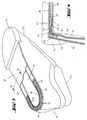
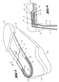
- FIG. 1 shows a shank 11 with a shank upper material 13, a sheath feed material 15 and an elastic mesh band 17, via which an upper material end region 19 and a Futtermaterialend Scheme 21 are interconnected.
- the net strip 17 shown enlarged in FIG. 2 comprises a first longitudinal web 23 and a second longitudinal web 25, which are connected to one another by means of transverse webs 27.
- the first longitudinal web 23 is connected to the upper material end region 19 via a first seam 29 and to the Futtermaterialend Scheme 21 via a second seam 31.
- At least the second longitudinal web 25 is made of elastic material and is sewn to the Futtermaterialend Scheme 21 under longitudinal expansion bias.
- the first longitudinal ridge 23 may, but need not be elastic.
- the transverse webs 27 may be elastic, but are preferably not elastic.
- the two longitudinal webs 23 and 25 made of latex rubber or other (rubbery) material with elastic behavior (eg Lycra etc.) and the transverse webs 27 of polyamide, polyester or a similar material.
- the length of the transverse webs 27 and their distance from each other are chosen so that the existing in the shaft lining material 15 waterproof, water vapor permeable functional layer by the mesh band 17 can be adequately wetted with sealing material.
- An embodiment of a presently preferred elastic net strip has a width of about 10 mm, of which the two longitudinal webs 23 and 25 each about 3.5 mm and the clear distance, ie the length of the exposed transverse webs 27, about 3 mm occupy. In this case, the transverse webs 27-a distance of about 0.25 mm from each other.
- the viscosity of the sealing material is taken into account, for which the mesh tape should be penetrable.
- the net 17 has a width of about 15 mm.
- One embodiment of the net of the above dimensions is a woven, elastic tape having warp or longitudinal yarns of natural rubber and textured polyamide yarns, with a material composition of 40% natural rubber, 40% monofilipolyamide and 20% textured polyamide being preferred.
- Such a mesh tape is preferably made by a weaving process.
- warp or longitudinal threads are only in the region of the two longitudinal webs 23 and 25, so that the transverse or weft threads in the area between the two longitudinal webs 23 and 25 are exposed and thus can form the transverse webs 27.
- longitudinal threads for the longitudinal webs 23 and 25 are elastic longitudinal threads, preferably made of rubber, and non-elastic longitudinal threads, preferably made of polyamide, used for the transverse webs only non-elastic threads, preferably also made of polyamide.
- the elastic longitudinal threads are stretched by a predetermined amount and the non-elastic longitudinal threads are arranged parallel to the stretched elastic longitudinal threads. In this state, the longitudinal threads with the Cross threads interwoven. After weaving, the elastic longitudinal threads pull together and the net 17 relaxes accordingly.
- the first longitudinal ridge 23 is first sewn to the upper end 19, under longitudinal expansion bias of the first longitudinal ridge 23.
- the first longitudinal ridge 23 at the Obermaterialend Scheme 19 -sews the remaining part of the net with the second longitudinal web 25 and the transverse webs 27 inwardly, as shown in Fig. 1 in the heel region of the shaft.
- This folding is a consequence of the sewing of the first longitudinal web 23 on the upper material end region 19 under longitudinal expansion prestressing.
- By folding over the net 17 assumes a position in which it extends substantially parallel to the outsole to be applied later. This folding is also done in the toe area of the shaft 11, which then in most cases will lead to folding the net band 17 over its entire length.
- the folding of the mesh tape 17 is shown only in the heel region of the shaft 11 in order to better represent the connection of the shaft lining material 15 with the net 17 in the forefoot area.
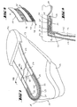
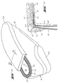
- FIGS. 3 to 11 show various embodiments of footwear according to the invention in a later stage of manufacture than FIG. 1, in each case in a perspective plan view of the underside, partly in sectional view, and a partial cross-sectional view.
- the embodiments illustrated in FIGS. 3 to 11 differ from one another with regard to the sealing material and / or the sole construction.
- FIGS. 3 and 4 show an embodiment of footwear according to the invention, which is stretched on a strip 43 and has a gestrobelte insole and a glued-on outsole.
- an insole 33 is connected to the second longitudinal rib 25 of the elastic mesh band 17 by means of a stitching seam 55.
- the net 17 extends in the plane of the insole 33rd
- a sealing material in the form of e.g. Sealing adhesive 37 applied, which forms a circumferential in Schaftend Schemeswhosraum closed sealing material zone in which the sealing adhesive 37 penetrates the mesh belt 17 penetrating to the functional layer, the shaft lining material 15 and waterproof seals this.
- a sealing plate 39 (a gasket) covered, which has a waterproof functional layer, which is preferably also permeable to water vapor in order to maintain breathability even in the sole area of the shoe despite waterproofness.
- the sealing plate 39 need not - as shown in Fig. 3 - to extend to the outer edge of the net 17. It suffices an extension, by means of which the insole 33 and the Strobelnaht 35 are covered, wherein the sealing plate 39 overlaps with the sealing adhesive 37 in order to achieve a secure seal of the sole construction.
- a sealing adhesive 37 is preferably used reactive hot melt adhesive, in particular polyurethane reactive hot melt adhesive due to its high creep in the liquid, unreacted state and its high and durable water resistance in the fully reacted. Due to its high creep ability In the liquid, unreacted state of the reactive hot melt adhesive has the ability to penetrate the elastic mesh 17 to a particularly high degree, penetrate to the functional layer of the shaft lining material 15 and to wet them, the transverse webs of the net 17 are infiltrated by the reactive hot melt adhesive and thus a full-surface wetting the functional layer is enabled with the reactive hot melt adhesive, and thus to prevent the penetration of water, which has penetrated over the upper upper material 13 to the net 17, from reaching the inside of the shaft lining material 15 and thus to the inside of the shoe.
- reactive hot melt adhesive in particular polyurethane reactive hot melt adhesive due to its high creep in the liquid, unreacted state and its high and durable water resistance in the fully reacted. Due to its high creep ability In the liquid, unreacted state of the reactive hot melt adhesive has the
- the folded-over part of the sole-side shank end region is attached to the insole 33 by means of adhesive bonding.
- the gumming is done by means of a Zwickklebstoffs 45, which can be seen in the cross-sectional view in Fig. 6.
- sealant adhesive 37 preferably in the form of reactive hot melt adhesive, as has already been explained in connection with the embodiment of FIGS. 3 and 4.
- a sealing plate 39 or a sheet-applied continuous layer of reactive hot melt adhesive may be provided in the event that the outsole 41 is not waterproof.
- FIGS. 7-9 show an embodiment of a bootless shoe in which the sole-side upper end region extending parallel to the outsole 41 is tensioned or lashed together by means of a lashing cord 49.
- the lashing cord 49 is guided in a cord traction tunnel 47, which is attached to the second longitudinal web 25 of the elastic net band 17, for example, in the manner shown in FIG.
- the drawstring tunnel 47 is in two places of the shoe circumference extending between the heel area and the toe area are open, here to grab the lashing 49, to tighten and knot.
- sealing tape 37 is applied to the mesh tape 17, preferably again in the form of reactive hot melt adhesive, which can be referenced for details with reference to the explanations in connection with FIG.
- Fig. 9 shows an embodiment in which the cord traction tunnel 47 is attached directly to the mesh belt 17
- Fig. 8 shows an embodiment in which an initially separate Schnurzugtunnel 47 with therein lashing 49 by means of the second seam 31 between the second longitudinal web 25th the net strip 17 and the Futtermaterialend Scheme 21 is sewn.
- the shoe structure according to FIGS. 7 to 9 can be modified by molding a sole made of a waterproof material, which may be a midsole or an outsole, onto the underside of the shaft end region, by means of which a sealing of the sole structure is effected , In this case, neither a gasket nor a sealing material layer or reactive hot melt adhesive layer is required.
- FIGS. 10 and 11 show an embodiment in which the sealing material is formed by sole material of a sole, which may be, for example, a midsole or the outsole 41.
- sole material of a sole which may be, for example, a midsole or the outsole 41.
- no sealing adhesive 37 and no gasket are applied.
- the shoe has a molded-on sole 41.
- the sealing function which is adopted in the embodiments of FIGS. 3 and 7 of separately applied sealant adhesive 37, exercises in the embodiment of FIG. 10 of the sole adhesive.
- a seal plate 39 as shown in the previous embodiments is not needed in the embodiment of Fig. 10 because the molded outsole 41 seals the entire area of the sole structure.
- FIG. 10 is only suitable for molded soled shoes
- the embodiments of FIGS. 5 and 7 may be used for non-molded, that is, adhered soles, which are plastic soles and thus waterproof soles can, so that the sealing plate 39 is not required, or to water-permeable soles, for example made of leather, in which case the sealing plate 39 is recommended to get the sole construction waterproof, the sealing plate is preferably not only waterproof but also water vapor permeable.
- Fig. 12 shows a partial sectional view of a pinch-bonded shoe structure with a molded-on sole 41, which may be a midsole or an outsole.
- a molded-on sole 41 which may be a midsole or an outsole.
- liquid sole material penetrates the mesh band 17, penetrates to the functional layer of the lining material 15 and seals the functional layer.
- a gasket or sealing material layer is therefore not required. Otherwise, the construction in FIG. 12 agrees with the construction shown in FIG.
- FIG. Fig. 13 shows two elliptical arches, an outer and an inner elliptical arc, which represent the longitudinal side connecting band and the connecting band end side connected to the upper end portion should.
- an arc sector S1 or an arc sector S2 is formed by means of the two rays of an angle. Both arc sectors S1 and S2 have the same angle w, referred to herein as the unit sector angle.
- the angular beams of the arc sector S1 define an outer arc length BO1 of the outer ellipse and an inner arc length BF1 of the inner ellipse.
- BO stands for arc length of the upper and BF for the arc length of the lining material.
- the angular beams of the arc sector S2 define an outer arc length BO2 of the outer ellipse and an inner arc length BF2 of the inner ellipse.
- the arc lengths BO1 and BO2 are duplicated and shifted as thick lines close to the arc length BF1 and BF2, respectively, to make clear the differences in length between BO1 and BF1 on the one hand and between BO2 and BF2 on the other hand.
- Suitable elastic material for the elastic longitudinal web or the elastic longitudinal webs of the elastic connecting band are in particular rubber, rubber, elastic plastics such as synthetic rubber, PVC, silicone, PU, and textile materials, in which rubber threads and / or threads are incorporated from such materials ,
- the elastic tie band has a stretch of at least about 20%.
- the tie tape has a stretch of at least about 30%, more preferably at least about 40%, and most preferably at least about 50%.
- These extensibility values have an elastic expansion ratio of at least 40%.
- the elastic elongation rate is 100%.
- at least the longitudinal web of the elastic connecting band to be connected to the lining material end region has the highest possible elastic extensibility in order to achieve the desired freedom from wrinkles at the points of the lower end region of the shaft which have a high curvature.
- Elasticity and restoring force values are determined by tensile strength measurements according to European Standard EN ISO 13934-1 dated April 1999 using an Instron tester (Istron being a manufacturer's name).
Landscapes
- Health & Medical Sciences (AREA)
- Epidemiology (AREA)
- General Health & Medical Sciences (AREA)
- Public Health (AREA)
- Engineering & Computer Science (AREA)
- Mechanical Engineering (AREA)
- Footwear And Its Accessory, Manufacturing Method And Apparatuses (AREA)
- Radar Systems Or Details Thereof (AREA)
- Adornments (AREA)
Claims (63)
- Tige de chaussure, comportant
une matière de revêtement de la tige (13) avec une zone d'extrémité de la matière de revêtement (19) se trouvant dans la zone d'extrémité inférieure de la tige,
une matière de doublure de la tige disposée sur la face intérieure de la matière de revêtement de la tige (13), comportant une couche fonctionnelle étanche à l'eau, avec une zone d'extrémité inférieure de la matière de doublure (21), la zone d'extrémité de la matière de doublure (21) comportant un bord de doublure non recouvert par la matière de revêtement de la tige (13),
et une bande de liaison (17) périphérique dans le sens de la circonférence de la zone d'extrémité de la tige, qui sur un premier côté longitudinal (23) est reliée avec la zone d'extrémité de la matière de revêtement (19), mais pas avec la zone d'extrémité de la matière de doublure (21) et qui sur un deuxième côté longitudinal est reliée avec la zone d'extrémité de la matière de doublure (21), mais pas avec la zone d'extrémité de la matière de revêtement (19),
la bande de liaison (17) présentant sur des endroits de courbure de la périphérie de la zone d'extrémité inférieure de la tige un trajet courbé correspondant au rayon de courbure local, avec une courbure plus ou moins importante des deux côtés longitudinaux de la bande de liaison, de façon à ce que pour un secteur de cintrage situé dans la courbure respective, avec un angle de secteur unitaire prédéfini, les longueurs de cintrage appartenant à ce secteur de cintrage des deux côtés longitudinaux de la bande de liaison se distinguent d'autant plus entre elles que la courbure est importante dans le secteur de cintrage respectivement considéré, sur des endroits à courbure convexe de la périphérie inférieure de la zone d'extrémité de la tige, la longueur du cintrage du premier côté longitudinal de la bande de liaison étant plus longue que la longueur de cintrage du deuxième côté longitudinal de la bande de liaison, à savoir en fonction des différentes courbures et longueurs de cintrage de la zone d'extrémité de la matière de revêtement et de la zone d'extrémité de la matière de doublure. - Tige de chaussure selon la revendication 1, sur laquelle sur des endroits de la périphérie de la zone d'extrémité de la tige à courbure concave, la longueur de cintrage du deuxième côté longitudinal de la bande de liaison est plus longue que la longueur de cintrage du premier côté longitudinal de la bande de liaison.
- Tige de chaussure selon la revendication 1 ou 2, sur laquelle la zone de doublure non recouverte par la matière de revêtement de la tige (13) est formée par un débordement de la zone d'extrémité de la matière de doublure (21) par rapport à la zone d'extrémité de la matière de revêtement (19).
- Tige de chaussure selon l'une quelconque des revendications 1 à 3, avec une bande de liaison sensiblement rigide, dans laquelle les différences de longueur de cintrage dépendant de la courbure respective des cintrages des deux côtés longitudinaux de la bande de liaison sont incorporées par une fabrication correspondante.
- Tige de chaussure selon la revendication 4, avec une bande de liaison découpée.
- Tige de chaussure selon la revendication 4, avec une bande de liaison injectée.
- Tige de chaussure selon l'une quelconque des revendications 1 à 3, avec une bande de liaison élastique, qui sur son premier côté longitudinal (23) est reliée avec la zone d'extrémité de la matière de revêtement (19), sous précontrainte par allongement longitudinal.
- Tige de chaussure selon l'une quelconque des revendications 1 à 3, avec une bande de liaison déformable, qui sur son premier côté longitudinal (23) est reliée avec la zone d'extrémité de la matière de revêtement (19), sous précontrainte par allongement longitudinal provoquant une déformation plastique.
- Tige de chaussure selon l'une quelconque des revendications 1 à 3, 7 et 8, sur laquelle sur son deuxième côté longitudinal, la bande de liaison (17) est reliée par son deuxième côté longitudinal avec la zone d'extrémité de la matière de doublure (21) sous précontrainte par allongement longitudinal.
- Tige de chaussure selon l'une quelconque des revendications 1 à 9, sur laquelle le premier côté longitudinal (23) de la bande de liaison (17) est cousu sur la zone d'extrémité de la matière de revêtement (19).
- Tige de chaussure selon l'une quelconque des revendications 1 à 10, sur laquelle le deuxième côté longitudinal (25) de la bande de liaison (17) est cousu sur la zone d'extrémité de la matière de doublure (21).
- Tige de chaussure selon l'une quelconque des revendications 1 à 11, dont la bande de liaison (17) n'est pas poreuse.
- Tige de chaussure -selon la revendication 12, dont la bande de liaison (17) est conçue en une matière d'étanchéité qui au moyen d'une énergie d'activation, choisie parmi les formes énergétiques : énergie thermique, énergie haute fréquence, énergie infrarouge et énergie UV est activable en un état liquide passager.
- Tige de chaussure selon la revendication 12 pour une chaussure à semelle moulée par injection, dont la bande de liaison (17) est en une matière pouvant être mise en fusion par la matière de semelle thermo-liquide, lors du moulage par injection de la semelle.
- Tige de chaussure selon l'une quelconque des revendications 12 à 14, dont la bande de liaison (17) est formée par un ruban de polyuréthane.
- Tige de chaussure selon l'une quelconque des revendications 1 à 11, dont la bande de liaison (17) est poreuse, de façon à pouvoir être pénétrée par de la matière d'étanchéité liquide (37 ; 41).
- Tige de chaussure selon la revendication 16, dont la bande de liaison (17) est formée par une bande en filet, qui sur son premier côté longitudinal comporte une première barrette longitudinale (23) et sur son deuxième côté longitudinal comporte une deuxième barrette longitudinale (25) qui sont reliées entre elles par l'intermédiaire de barrettes transversales (27).
- Tige de chaussure selon la revendication 17, sur laquelle au moins la deuxième barrette longitudinale (25) est conçue en une matière flexible élastique.
- Tige de chaussure selon la revendication 17 ou 18, sur laquelle les barrettes transversales (27) sont conçues en une matière non élastique.
- Tige de chaussure selon l'une quelconque des revendications 17 à 19, sur laquelle la bande en filet est tissée, des fils longitudinaux faisant office de fils de chaîne, dont au moins par rapport à la première barrette longitudinale (23), au moins une partie est élastique n'étant présents que dans les zones des barrettes longitudinales (23, 25) et les barrettes transversales (27) étant formées par des fils de trame.
- Tige de chaussure selon l'une quelconque des revendications 1 à 20, sur laquelle la zone d'extrémité de la matière de doublure (21) et le deuxième côté longitudinal (25) de la bande de liaison (17) sont reliés à un tunnel de traction d'une cordelette (47) dans lequel est placée une cordelette de serrage mobile en longueur (49) par rapport au tunnel de traction de la cordelette (47), par serrage de laquelle la zone inférieure d'extrémité de la tige se tend vers l'intérieur, de façon à ce que la zone inférieure d'extrémité de la tige avec le bord de la doublure et la bande de liaison (17) s'étendent dans la zone d'extension d'une semelle de marche (41) qui doit encore être montée.
- Tige de chaussure selon l'une quelconque des revendications 1 à 21, dont la couche fonctionnelle est perméable à la vapeur d'eau.
- Tige de chaussure selon la revendication 22, dont la couche fonctionnelle comporte une couche en PTFE microporeux.
- Tige de chaussure selon l'une quelconque des revendications 8 à 23, dont la bande de liaison (17) a une extensibilité d'au moins 20 %.
- Chaussure avec une tige de chaussure selon l'une quelconque des revendications 1 à 24.
- Chaussure selon la revendication 25, avec une matière d'étanchéité (37 ; 41) qui assure l'étanchéité à l'eau de la zone d'extrémité de la matière de doublure (21) dans une zone de matière d'étanchéité située dans la zone de la bande de liaison (17) qui est périphérique dans le sens de la circonférence de la zone d'extrémité de la tige.
- Chaussure selon la revendication 26, avec une semelle moulée par injection, dont la matière d'étanchéité est formée par une matière à semelle liquide (41) lors du moulage par injection de la semelle, qui en pénétrant dans la bande de liaison poreuse (17) assure l'étanchéité à l'eau d'au moins une partie de la largeur du bord de la doublure non recouverte par de la matière de revêtement de la tige.
- Chaussure selon la revendication 26, dont la matière d'étanchéité (37) est formée par une matière adhésive assurant l'étanchéité à l'eau à l'état durci, qui en pénétrant dans la bande de liaison poreuse (17) assure l'étanchéité à l'eau d'au moins une partie de la largeur du bord de la doublure non recouverte par de la matière de revêtement de la tige.
- Chaussure selon la revendication 28, avec une matière d'étanchéité (37) sous forme d'une matière adhésive fusible réactive, qui après réaction assure l'étanchéité à l'eau.
- Chaussure selon l'une quelconque des revendications 25 à 29, avec une semelle intérieure (33), la zone inférieure de la tige avec le bord de la doublure et la bande de liaison (17) s'étendant dans la zone d'extension de la semelle intérieure (33).
- Chaussure selon la revendication 30, sur laquelle la semelle intérieure (33) est reliée à la zone d'extrémité de la matière de doublure (21) et au deuxième côté longitudinal de la bande de liaison (17) par une couture Strobel (35).
- Chaussure selon la revendication 30, sur laquelle la zone d'extrémité inférieure de la tige est montée au moyen d'un adhésif de montage (45) sur une bordure périphérique inférieure de la semelle intérieure (33).
- Chaussure selon l'une quelconque des revendications 25 à 32, avec une couche d'étanchéité à l'eau à grande surface, qui est appliquée sur la face inférieure d'une zone d'extrémité rabattue de la tige, à la parallèle d'une semelle (41) qui doit encore être montée, de façon à assurer l'étanchéité d'une ouverture inférieure de la tige jusqu'à la zone de matière d'étanchéité.
- Chaussure selon la revendication 33, sur laquelle la couche d'étanchéité est formée par une plaque d'étanchéité (39) qui est collée sur la face inférieure de la semelle intérieure.
- Chaussure selon la revendication 34, dont la plaque d'étanchéité (39) comporte une couche fonctionnelle étanche à l'eau.
- Procédé de fabrication d'une tige de chaussure, constituée d'une matière de revêtement de la tige (13), et-d'une matière de doublure (15) disposée sur la face intérieure de la matière de revêtement de la tige (13) et comportant une couche fonctionnelle, avec les étapes de fabrication suivantes :on prépare une pièce de matière de revêtement de la tige coupée en forme de tige ;on prépare une pièce de matière de doublure coupée en forme de tige, d'une découpe telle, qu'après avoir disposé en bonne position la pièce de matière de doublure sur la face intérieure de la pièce de matière de revêtement de la tige, une zone d'extrémité inférieure de la pièce de matière de doublure comporte un bord de doublure non recouvert par de la matière de revêtement de la tige (13) ;sur toute sa circonférence, on coud le bord inférieur de la pièce de matière de revêtement de la tige sur un premier côté longitudinal (23) d'une bande de liaison (17)sur toute sa circonférence, on coud une extrémité inférieure du bord de la doublure sur un deuxième côté longitudinal de la bande de liaison (17) ;la bande de liaison (17) étant munie sur des zones de courbure de la périphérie inférieure de la zone d'extrémité de la tige d'un trajet cintré correspondant au rayon de courbure local, avec une courbure plus ou moins importante des deux côtés longitudinaux de la bande de liaison, de façon à ce que pour un secteur de cintrage situé dans la courbure respective, avec un angle de secteur unitaire prédéfini, les longueurs de cintrage appartenant à ce secteur de cintrage des deux côtés longitudinaux de la bande de liaison se distinguent d'autant plus entre elles que la courbure est importante dans le secteur de cintrage respectivement considéré, sur des endroits à courbure convexe de la périphérie inférieure de la zone d'extrémité de la tige, la longueur du cintrage du premier côté longitudinal de la bande de liaison étant confectionnée pour être plus longue que la longueur de cintrage du deuxième côté longitudinal de la bande de liaison, à savoir en fonction des différentes courbures et longueurs de cintrage de la zone d'extrémité de la matière de revêtement et de la zone d'extrémité de la matière de doublure.
- Procédé selon la revendication 36, au cours duquel sur des endroits de la circonférence de la zone d'extrémité de la tige à courbure concave, la longueur de cintrage du deuxième côté longitudinal de la bande de liaison est confectionnée pour être plus longue que la longueur de cintrage du premier côté longitudinal de la bande de liaison.
- Procédé selon la revendication 36 ou 37, au cours duquel la zone de doublure non recouverte par la matière de revêtement de la tige (13) est formée par un débordement de la zone d'extrémité de la matière de doublure (21) par rapport à la zone d'extrémité de la matière de revêtement (19).
- Procédé selon l'une quelconque des revendications 36 à 38 sous utilisation d'une bande de liaison sensiblement rigide, dans laquelle on incorpore par une fabrication correspondante les différences de longueur de cintrage dépendant de la courbure respective des cintrages des deux côtés longitudinaux de la bande de liaison.
- Procédé selon la revendication 39, sous utilisation d'une bande de liaison découpée.
- Procédé selon la revendication 39, sous utilisation d'une bande de liaison injectée.
- Procédé selon l'une quelconque des revendications 36 à 38, sous utilisation d'une bande de liaison élastique, qu'on relie sur son premier côté longitudinal (23) avec la zone d'extrémité de la matière de revêtement (19), sous précontrainte par allongement longitudinal.
- Procédé selon l'une quelconque des revendications 36 à 38, sous utilisation d'une bande de liaison déformable (17), qu'on relie sur son premier côté longitudinal (23) avec la zone d'extrémité de la matière de revêtement (19), sous précontrainte par allongement longitudinal provoquant une déformation plastique.
- Procédé selon l'une quelconque des revendications 36 à 38, 42 et 43, au cours duquel on coud l'extrémité inférieure du bord de la doublure sur le deuxième côté longitudinal (25) de la bande de liaison élastique (17), sous précontrainte d'allongement en longueur de la bande de liaison (17) provoquant une déformation élastique.
- Procédé selon l'une quelconque des revendications 36 à 44, sous utilisation d'une bande de liaison (17) qui est conçue en une matière d'étanchéité qui au moyen d'une énergie d'activation, choisie parmi les formes énergétiques : énergie thermique, énergie haute fréquence, énergie infrarouge et énergie UV est activable en un état liquide passager.
- Procédé selon l'une quelconque des revendications 36 à 44, sous utilisation d'une bande de liaison (17) en une matière pouvant être mise en fusion par la matière de semelle thermo-liquide, lors du moulage par injection de la semelle (41).
- Procédé selon la revendication 45 ou 46, sous utilisation d'une bande de liaison (17) formée par un ruban de polyuréthane.
- Procédé selon l'une quelconque des revendications 36 à 44, sous utilisation d'une bande de liaison (17) poreuse, pouvant être pénétrée par de la matière d'étanchéité liquide (37 ; 41).
- Procédé selon l'une quelconque des revendications 36 à 44, au cours duquel on utilise en tant que bande de liaison (17) une bande en filet, qui sur son premier côté longitudinal comporte une première barrette longitudinale (23) et sur son deuxième côté longitudinal comporte une deuxième barrette longitudinale (25) qui sont reliées entre elles par l'intermédiaire de barrettes transversales (27).
- Procédé selon la revendication 49, en utilisant une bande en filet sur laquelle au moins la deuxième barrette longitudinale (25) est conçue en une matière flexible élastique.
- Procédé selon la revendication 49 ou 50, en utilisant une bande en filet sur laquelle les barrettes transversales (27) sont conçues en une matière non élastique.
- Procédé selon l'une quelconque des revendications 36 à 51, au cours duquel on utilise une bande de liaison (17) avec une extensibilité d'au moins 20 %.
- Procédé selon l'une quelconque des revendications 36 à 52, au cours duquel on relie l'extrémité inférieure du bord de la doublure et le deuxième côté longitudinal (25) de la bande de liaison (17) avec un tunnel de traction d'une cordelette (47) réceptionnant une cordelette de serrage mobile en longueur (49) par rapport au tunnel de traction de cordelette (47), et par serrage de la cordelette de serrage (49), on tend vers l'intérieur une zone inférieure d'extrémité de la tige avec le bord de la doublure et la bande de liaison (17), de façon à ce que la zone inférieure d'extrémité de la tige avec le bord de la doublure et la bande de liaison (17) s'étendent dans le sens d'extension d'une semelle de marche (41) qui doit encore être montée.
- Procédé selon l'une quelconque des revendications 36 à 53, au cours duquel on assure l'étanchéité à l'eau de la couche fonctionnelle de la zone d'extrémité de la matière de doublure (21) au moins dans une zone de matière d'étanchéité se trouvant dans la région de la bande de liaison (17) s'étendant dans le sens périphérique de l'extrémité de la tige à l'aide d'une matière d'étanchéité (37 ; 41).
- Procédé de fabrication de chaussures, au cours duquel on fabrique une tige selon le procédé selon l'une quelconque des revendications 36 à 53 et on assure l'étanchéité à l'eau de la couche fonctionnelle de la zone d'extrémité de la matière de doublure (21) au moins dans une zone de matière d'étanchéité se trouvant dans la région de la bande de liaison (17) s'étendant dans le sens périphérique de l'extrémité de la tige à l'aide d'une matière d'étanchéité (37 ; 41).
- Procédé selon la revendication 55, au cours duquel on forme par moulage sur la tige (11) une semelle (41) en matière à semelle liquide lors du moulage par injection, qui en pénétrant dans la bande de liaison poreuse (17) assure l'étanchéité à l'eau d'au moins une partie de la largeur du bord de la doublure non recouvert par de la matière de revêtement de la tige (13).
- Procédé selon la revendication 55, sous utilisation d'une matière d'étanchéité (37) sous la forme d'une matière adhésive d'étanchéité assurant l'étanchéité à l'eau à l'état durci, qui en pénétrant dans la bande de liaison poreuse (17) assure l'étanchéité à l'eau d'au moins une partie du bord de la doublure non recouvert par de la matière de revêtement de la tige (13).
- Procédé selon la revendication 57, sous utilisation d'une matière d'étanchéité (37) sous la forme d'une matière adhésive fusible réactive, qui après réaction assure l'étanchéité à l'eau.
- Procédé selon l'une quelconque des revendications 55 à 58, au cours duquel on oriente une zone d'extrémité inférieure de la tige comportant le bord de la doublure et la bande de liaison (17) de façon à ce qu'elle s'étende dans le sens d'extension d'une semelle de marche (41) qui doit encore être montée et on relie la zone d'extrémité inférieure de la tige avec une semelle intérieure (33).
- Procédé selon la revendication 59, au cours duquel on relie la semelle intérieure (33) avec le bord de la doublure et avec le deuxième côté longitudinal de la bande de liaison (17) par une couture Strobel (35).
- Procédé selon la revendication 59, au cours duquel on relie la zone inférieure d'extrémité de la tige au moyen d'un adhésif de montage (45) sur un bord périphérique inférieur de la semelle intérieure (33).
- Procédé selon l'une quelconque des revendications 55 à 61, au cours duquel on applique sur la face inférieure d'une zone d'extrémité de la tige rabattue dans le sens d'extension de la semelle une couche d'étanchéité à l'eau à grande surface, qui assure l'étanchéité d'une ouverture inférieure de la tige jusqu'à la zone de matière d'étanchéité.
- Procédé selon la revendication 62, au cours duquel pour la couche d'étanchéité, on colle une plaque d'étanchéité (39) sur la face inférieure de la semelle inférieure.
Priority Applications (1)
| Application Number | Priority Date | Filing Date | Title |
|---|---|---|---|
| SI200330390T SI1476038T1 (sl) | 2002-02-22 | 2003-02-21 | Zgornji del cevlja in z njim sestavljena obutev in postopek za njegovo izdelavo |
Applications Claiming Priority (3)
| Application Number | Priority Date | Filing Date | Title |
|---|---|---|---|
| DE10207663A DE10207663C1 (de) | 2002-02-22 | 2002-02-22 | Schuhschaft und damit aufgebautes Schuhwerk und Verfahren zu deren Herstellung |
| DE10207663 | 2002-02-22 | ||
| PCT/EP2003/001811 WO2003070041A1 (fr) | 2002-02-22 | 2003-02-21 | Tige de chaussure et chaussure fabriquee avec cette tige, et procede de production y relatif |
Publications (2)
| Publication Number | Publication Date |
|---|---|
| EP1476038A1 EP1476038A1 (fr) | 2004-11-17 |
| EP1476038B1 true EP1476038B1 (fr) | 2006-05-10 |
Family
ID=27635253
Family Applications (1)
| Application Number | Title | Priority Date | Filing Date |
|---|---|---|---|
| EP03704678A Expired - Lifetime EP1476038B1 (fr) | 2002-02-22 | 2003-02-21 | Tige de chaussure et chaussure fabriquee avec cette tige, et procede de production y relatif |
Country Status (8)
| Country | Link |
|---|---|
| US (1) | US7127833B2 (fr) |
| EP (1) | EP1476038B1 (fr) |
| CN (1) | CN100403950C (fr) |
| AT (1) | ATE325553T1 (fr) |
| AU (1) | AU2003206948A1 (fr) |
| DE (2) | DE10207663C1 (fr) |
| ES (1) | ES2260608T3 (fr) |
| WO (1) | WO2003070041A1 (fr) |
Families Citing this family (38)
| Publication number | Priority date | Publication date | Assignee | Title |
|---|---|---|---|---|
| DE10207663C1 (de) * | 2002-02-22 | 2003-08-28 | Gore W L & Ass Gmbh | Schuhschaft und damit aufgebautes Schuhwerk und Verfahren zu deren Herstellung |
| ITPD20020264A1 (it) * | 2002-10-15 | 2004-04-16 | Geox Spa | Suola impermeabilizzata e traspirante perfezionata per calzature e suo procedimento di realizzazione. |
| DE10300012A1 (de) * | 2003-01-02 | 2004-07-22 | W.L. Gore & Associates Gmbh | Wasserdichtes Schuhwerk mit elastischem Verbindungsband |
| US7043856B2 (en) * | 2004-09-07 | 2006-05-16 | Chuang-Chuan Chen | Shoes with side panel for connection outsole |
| FR2903866B1 (fr) * | 2006-07-21 | 2009-03-20 | Salomon Sa | Chaussure respiro-etanche |
| ITPD20070106A1 (it) * | 2007-03-23 | 2008-09-24 | Geox Spa | Sottopiede di montaggio impermeabile all'acqua e permeabile al vapord'acqua e calzatura realizzata con detto sottopiede |
| US8544191B2 (en) * | 2007-04-10 | 2013-10-01 | Reebok International Limited | Smooth shoe uppers and methods for producing them |
| CN101772313A (zh) * | 2007-06-04 | 2010-07-07 | 辛帕特克斯技术有限公司 | 用于制造不透水、透气的鞋子的方法 |
| US20090119948A1 (en) * | 2007-11-09 | 2009-05-14 | David Ortley | Golf Shoe Mesh Upper with a Moisture Resistant Guard |
| DE102008027856A1 (de) * | 2008-06-11 | 2009-12-24 | W. L. Gore & Associates Gmbh | Schuh mit Belüftung im unteren Schaftbereich und dafür verwendbares luftdurchlässiges Abstandsgebilde |
| IT1393590B1 (it) * | 2009-04-02 | 2012-04-27 | Stemma Srl | Metodo per la produzione di calzature traspiranti ed impermeabili all'acqua. |
| EP2238850B1 (fr) | 2009-04-10 | 2014-08-13 | Geox S.p.A. | Chaussure imperméable et perméable à la vapeur |
| ES2391874T3 (es) * | 2009-04-10 | 2012-11-30 | Geox S.P.A. | Procedimiento para la fabricación de calzado impermeable al agua y permeable al vapor |
| US8296970B2 (en) * | 2009-09-29 | 2012-10-30 | W. L. Gore & Associates, Inc. | Waterproof breathable footwear having hybrid upper construction |
| DE102010006151A1 (de) * | 2010-01-29 | 2011-08-04 | W. L. Gore & Associates GmbH, 85640 | Schaftanordnung für Schuhwerk sowie Schuhwerk damit |
| IT1398094B1 (it) | 2010-02-10 | 2013-02-07 | Geox Spa | Calzatura con tomaia e suola impermeabili |
| IT1398822B1 (it) * | 2010-03-17 | 2013-03-21 | Calzaturificio Mexas S R L | Metodo per la realizzazione di una calzatura e calzatura così ottenuta |
| IT1403989B1 (it) * | 2010-09-28 | 2013-11-08 | Geox Spa | Calzatura traspirante con suola impermeabile e traspirante |
| JP2014516844A (ja) * | 2011-06-17 | 2014-07-17 | コロンビア スポーツウエア ノース アメリカ、インコーポレイテッド | シェルアウトソールにアッパーを防水結合するためのセルフシール加硫処理システム |
| US20130055598A1 (en) * | 2011-09-02 | 2013-03-07 | Robert J. Wiener | Direct Attach Waterproof Footwear |
| ITTV20130023A1 (it) | 2013-02-25 | 2014-08-26 | Roberto Pierobon | Calzatura impermeabile e traspirante e relativo metodo di realizzazione |
| US11666113B2 (en) | 2013-04-19 | 2023-06-06 | Adidas Ag | Shoe with knitted outer sole |
| DE102013207156A1 (de) | 2013-04-19 | 2014-10-23 | Adidas Ag | Schuh, insbesondere ein Sportschuh |
| DE102013207163B4 (de) | 2013-04-19 | 2022-09-22 | Adidas Ag | Schuhoberteil |
| DE102013207155B4 (de) | 2013-04-19 | 2020-04-23 | Adidas Ag | Schuhoberteil |
| DE102014202432B4 (de) | 2014-02-11 | 2017-07-27 | Adidas Ag | Verbesserter Fußballschuh |
| CN104188270A (zh) * | 2014-08-31 | 2014-12-10 | 成都卡美多鞋业有限公司 | 采用绷楦法制作鞋子的方法 |
| DE102014220087B4 (de) | 2014-10-02 | 2016-05-12 | Adidas Ag | Flachgestricktes Schuhoberteil für Sportschuhe |
| WO2016139144A1 (fr) * | 2015-03-02 | 2016-09-09 | Evonik Degussa Gmbh | Adhésifs à faibles valeurs de cov et de condensation |
| US20160302517A1 (en) * | 2015-04-17 | 2016-10-20 | Wolverine World Wide, Inc. | Sole assembly for an article of footwear |
| CN105455312B (zh) * | 2015-11-23 | 2018-07-13 | 际华三五一五皮革皮鞋有限公司 | 减少天然鞋用面革松泡的辅助工艺 |
| TWI615105B (zh) * | 2016-03-07 | 2018-02-21 | 重慶股份有限公司 | 製造鞋幫之方法及系統 |
| EP3801112B1 (fr) | 2018-05-30 | 2023-03-08 | NIKE Innovate C.V. | Article chaussant et procédé de fabrication d'article chaussant |
| CN109008057A (zh) * | 2018-09-25 | 2018-12-18 | 泉州寰球鞋服有限公司 | 生活防水鞋的制造方法 |
| US20200147911A1 (en) * | 2018-11-14 | 2020-05-14 | Dean Shoes Company Ltd | Manufacturing method of injection molded composite shoe sole and sole thereof |
| US20220000214A1 (en) * | 2018-12-04 | 2022-01-06 | Ecco Sko A/S | An article of footwear |
| EP4021239A4 (fr) * | 2019-08-30 | 2023-08-23 | Lululemon Athletica Canada Inc. | Semelle intercalaire à deux couches |
| WO2021164837A1 (fr) * | 2020-02-19 | 2021-08-26 | Ecco Sko A/S | Chaussure perméable à l'air et imperméable à l'eau |
Family Cites Families (16)
| Publication number | Priority date | Publication date | Assignee | Title |
|---|---|---|---|---|
| CA962021A (en) * | 1970-05-21 | 1975-02-04 | Robert W. Gore | Porous products and process therefor |
| US4421742A (en) * | 1977-02-08 | 1983-12-20 | Dr. Werner Freyberg Chemische Fabrik Delitia Nachf. | Phosphine producing pesticide and method of manufacture therefor |
| US4194041A (en) * | 1978-06-29 | 1980-03-18 | W. L. Gore & Associates, Inc. | Waterproof laminate |
| CA1191439A (fr) * | 1982-12-02 | 1985-08-06 | Cornelius M.F. Vrouenraets | Produit flexible multicouche |
| KR890001484A (ko) * | 1987-07-08 | 1989-03-27 | 존 에스. 캠벨 | 방 수 화 |
| DE3840087A1 (de) * | 1988-11-28 | 1990-05-31 | Wagner Lowa Schuhfab | Schuh - stichwort: kunststoffzwickrand |
| ES2094445T3 (es) * | 1992-10-17 | 1997-01-16 | Akzo Nobel Nv | Calzado estanco al agua. |
| US5329807A (en) * | 1993-06-18 | 1994-07-19 | W. L. Gore & Associates, Inc. | Centrifuge test apparatus for footwear and apparel |
| DE19503405C1 (de) * | 1995-02-02 | 1996-07-04 | Media Point Werbe Und Warenver | Schuhwerk |
| WO1997024940A1 (fr) | 1996-01-10 | 1997-07-17 | Akzo Nobel N.V. | Chaussure etanche |
| AU6475699A (en) * | 1998-10-28 | 2000-05-15 | W.L. Gore & Associates Gmbh | Sealed shoe and a method for the production thereof |
| EP1124460B1 (fr) * | 1998-10-28 | 2004-06-16 | W.L. GORE & ASSOCIATES GmbH | Chaussure dotee d'une structure semelle etancheifiee et son procede de production |
| DE19938139A1 (de) * | 1998-11-17 | 2001-04-26 | Gore W L & Ass Gmbh | Schuhwerk mit abgedichtetem Sohlenaufbau und Verfahren zu dessen Herstellung |
| DE10003677C1 (de) * | 2000-01-28 | 2001-08-23 | Ricosta Schuhfabriken Gmbh | Wasserdichter Schuh und Verfahren zu dessen Herstellung |
| IT1317368B1 (it) * | 2000-10-10 | 2003-06-16 | Nottington Holding Bv | Struttura di calzatura impermeabile con suola o intersuola stampatasulla tomaia. |
| DE10207663C1 (de) * | 2002-02-22 | 2003-08-28 | Gore W L & Ass Gmbh | Schuhschaft und damit aufgebautes Schuhwerk und Verfahren zu deren Herstellung |
-
2002
- 2002-02-22 DE DE10207663A patent/DE10207663C1/de not_active Expired - Fee Related
-
2003
- 2003-02-21 AT AT03704678T patent/ATE325553T1/de active
- 2003-02-21 WO PCT/EP2003/001811 patent/WO2003070041A1/fr not_active Application Discontinuation
- 2003-02-21 EP EP03704678A patent/EP1476038B1/fr not_active Expired - Lifetime
- 2003-02-21 CN CNB038040344A patent/CN100403950C/zh not_active Expired - Lifetime
- 2003-02-21 ES ES03704678T patent/ES2260608T3/es not_active Expired - Lifetime
- 2003-02-21 US US10/504,791 patent/US7127833B2/en not_active Expired - Lifetime
- 2003-02-21 AU AU2003206948A patent/AU2003206948A1/en not_active Abandoned
- 2003-02-21 DE DE50303286T patent/DE50303286D1/de not_active Expired - Lifetime
Also Published As
| Publication number | Publication date |
|---|---|
| EP1476038A1 (fr) | 2004-11-17 |
| WO2003070041A1 (fr) | 2003-08-28 |
| DE50303286D1 (de) | 2006-06-14 |
| ATE325553T1 (de) | 2006-06-15 |
| ES2260608T3 (es) | 2006-11-01 |
| CN100403950C (zh) | 2008-07-23 |
| CN1633248A (zh) | 2005-06-29 |
| US7127833B2 (en) | 2006-10-31 |
| US20050138845A1 (en) | 2005-06-30 |
| AU2003206948A1 (en) | 2003-09-09 |
| DE10207663C1 (de) | 2003-08-28 |
Similar Documents
| Publication | Publication Date | Title |
|---|---|---|
| EP1476038B1 (fr) | Tige de chaussure et chaussure fabriquee avec cette tige, et procede de production y relatif | |
| EP1578222B1 (fr) | Chaussure impermeable comprenant une bande de liaison elastique | |
| EP0445198B1 (fr) | Chaussure caracterisee par une trepointe en plastique | |
| EP1124457B1 (fr) | Chaussure etancheifiee et son procede de production | |
| EP0298360B1 (fr) | Chaussure imperméable | |
| EP1202643B1 (fr) | Chaussure avec ensemble semelle etancheifie et procede de fabrication de cette chaussure | |
| EP0714612A1 (fr) | Chaussure de protection | |
| EP1622476A1 (fr) | Article chaussant impermeable a l'eau et procede de fabrication dudit article | |
| EP2160113A1 (fr) | Procédé de production d'un article chaussant étanche et aéré | |
| EP1002474A1 (fr) | Article chaussant rendu etanche par coincement des rebords de l'empeigne et procede de sa fabrication | |
| EP1124460B1 (fr) | Chaussure dotee d'une structure semelle etancheifiee et son procede de production | |
| EP1280429B1 (fr) | Chaussure et insert de couche fonctionnelle pour chaussure | |
| DE60004238T2 (de) | Schuhwerk mit Abdichtungselement | |
| EP1124458B1 (fr) | Chaussure dotee d'un rempli d'etancheite et son procede de production | |
| DE4419803A1 (de) | Bandsohlenmaterialschicht und ihre Verwendung im Schuhwerk | |
| DE19547276A1 (de) | Wasserdichter Schuh und Verfahren zu dessen Herstellung | |
| DE20315772U1 (de) | Wasserdichtes Schuhwerk mit elastischem Verbindungsband | |
| DE60104108T2 (de) | Schuh mit abgedichtetem zwickeinschlag und verfahren zu dessen herstellung | |
| DE19938139A1 (de) | Schuhwerk mit abgedichtetem Sohlenaufbau und Verfahren zu dessen Herstellung |
Legal Events
| Date | Code | Title | Description |
|---|---|---|---|
| PUAI | Public reference made under article 153(3) epc to a published international application that has entered the european phase |
Free format text: ORIGINAL CODE: 0009012 |
|
| 17P | Request for examination filed |
Effective date: 20040614 |
|
| AK | Designated contracting states |
Kind code of ref document: A1 Designated state(s): AT BE BG CH CY CZ DE DK EE ES FI FR GB GR HU IE IT LI LU MC NL PT SE SI SK TR |
|
| AX | Request for extension of the european patent |
Extension state: AL LT LV MK RO |
|
| GRAP | Despatch of communication of intention to grant a patent |
Free format text: ORIGINAL CODE: EPIDOSNIGR1 |
|
| GRAS | Grant fee paid |
Free format text: ORIGINAL CODE: EPIDOSNIGR3 |
|
| GRAA | (expected) grant |
Free format text: ORIGINAL CODE: 0009210 |
|
| AK | Designated contracting states |
Kind code of ref document: B1 Designated state(s): AT BE BG CH CY CZ DE DK EE ES FI FR GB GR HU IE IT LI LU MC NL PT SE SI SK TR |
|
| AX | Request for extension of the european patent |
Extension state: RO |
|
| PG25 | Lapsed in a contracting state [announced via postgrant information from national office to epo] |
Ref country code: SK Free format text: LAPSE BECAUSE OF FAILURE TO SUBMIT A TRANSLATION OF THE DESCRIPTION OR TO PAY THE FEE WITHIN THE PRESCRIBED TIME-LIMIT Effective date: 20060510 Ref country code: SI Free format text: LAPSE BECAUSE OF FAILURE TO SUBMIT A TRANSLATION OF THE DESCRIPTION OR TO PAY THE FEE WITHIN THE PRESCRIBED TIME-LIMIT Effective date: 20060510 Ref country code: NL Free format text: LAPSE BECAUSE OF FAILURE TO SUBMIT A TRANSLATION OF THE DESCRIPTION OR TO PAY THE FEE WITHIN THE PRESCRIBED TIME-LIMIT Effective date: 20060510 Ref country code: IT Free format text: LAPSE BECAUSE OF FAILURE TO SUBMIT A TRANSLATION OF THE DESCRIPTION OR TO PAY THE FEE WITHIN THE PRESCRIBED TIME-LIMIT;WARNING: LAPSES OF ITALIAN PATENTS WITH EFFECTIVE DATE BEFORE 2007 MAY HAVE OCCURRED AT ANY TIME BEFORE 2007. THE CORRECT EFFECTIVE DATE MAY BE DIFFERENT FROM THE ONE RECORDED. Effective date: 20060510 Ref country code: IE Free format text: LAPSE BECAUSE OF FAILURE TO SUBMIT A TRANSLATION OF THE DESCRIPTION OR TO PAY THE FEE WITHIN THE PRESCRIBED TIME-LIMIT Effective date: 20060510 Ref country code: FI Free format text: LAPSE BECAUSE OF FAILURE TO SUBMIT A TRANSLATION OF THE DESCRIPTION OR TO PAY THE FEE WITHIN THE PRESCRIBED TIME-LIMIT Effective date: 20060510 Ref country code: CZ Free format text: LAPSE BECAUSE OF FAILURE TO SUBMIT A TRANSLATION OF THE DESCRIPTION OR TO PAY THE FEE WITHIN THE PRESCRIBED TIME-LIMIT Effective date: 20060510 |
|
| REG | Reference to a national code |
Ref country code: GB Ref legal event code: FG4D Free format text: NOT ENGLISH |
|
| REG | Reference to a national code |
Ref country code: CH Ref legal event code: NV Representative=s name: BRAUNPAT BRAUN EDER AG Ref country code: CH Ref legal event code: EP |
|
| GBT | Gb: translation of ep patent filed (gb section 77(6)(a)/1977) |
Effective date: 20060510 |
|
| REF | Corresponds to: |
Ref document number: 50303286 Country of ref document: DE Date of ref document: 20060614 Kind code of ref document: P |
|
| REG | Reference to a national code |
Ref country code: IE Ref legal event code: FG4D Free format text: LANGUAGE OF EP DOCUMENT: GERMAN |
|
| PG25 | Lapsed in a contracting state [announced via postgrant information from national office to epo] |
Ref country code: DK Free format text: LAPSE BECAUSE OF FAILURE TO SUBMIT A TRANSLATION OF THE DESCRIPTION OR TO PAY THE FEE WITHIN THE PRESCRIBED TIME-LIMIT Effective date: 20060810 |
|
| REG | Reference to a national code |
Ref country code: SE Ref legal event code: TRGR |
|
| PG25 | Lapsed in a contracting state [announced via postgrant information from national office to epo] |
Ref country code: PT Free format text: LAPSE BECAUSE OF FAILURE TO SUBMIT A TRANSLATION OF THE DESCRIPTION OR TO PAY THE FEE WITHIN THE PRESCRIBED TIME-LIMIT Effective date: 20061010 |
|
| NLV1 | Nl: lapsed or annulled due to failure to fulfill the requirements of art. 29p and 29m of the patents act | ||
| REG | Reference to a national code |
Ref country code: ES Ref legal event code: FG2A Ref document number: 2260608 Country of ref document: ES Kind code of ref document: T3 |
|
| ET | Fr: translation filed | ||
| REG | Reference to a national code |
Ref country code: IE Ref legal event code: FD4D |
|
| PG25 | Lapsed in a contracting state [announced via postgrant information from national office to epo] |
Ref country code: MC Free format text: LAPSE BECAUSE OF NON-PAYMENT OF DUE FEES Effective date: 20070228 |
|
| PLBE | No opposition filed within time limit |
Free format text: ORIGINAL CODE: 0009261 |
|
| STAA | Information on the status of an ep patent application or granted ep patent |
Free format text: STATUS: NO OPPOSITION FILED WITHIN TIME LIMIT |
|
| 26N | No opposition filed |
Effective date: 20070213 |
|
| BERE | Be: lapsed |
Owner name: W.L. GORE & ASSOCIATES G.M.B.H. Effective date: 20070228 |
|
| PG25 | Lapsed in a contracting state [announced via postgrant information from national office to epo] |
Ref country code: BE Free format text: LAPSE BECAUSE OF NON-PAYMENT OF DUE FEES Effective date: 20070228 |
|
| PG25 | Lapsed in a contracting state [announced via postgrant information from national office to epo] |
Ref country code: GR Free format text: LAPSE BECAUSE OF FAILURE TO SUBMIT A TRANSLATION OF THE DESCRIPTION OR TO PAY THE FEE WITHIN THE PRESCRIBED TIME-LIMIT Effective date: 20060811 |
|
| PG25 | Lapsed in a contracting state [announced via postgrant information from national office to epo] |
Ref country code: BG Free format text: LAPSE BECAUSE OF FAILURE TO SUBMIT A TRANSLATION OF THE DESCRIPTION OR TO PAY THE FEE WITHIN THE PRESCRIBED TIME-LIMIT Effective date: 20060810 |
|
| PG25 | Lapsed in a contracting state [announced via postgrant information from national office to epo] |
Ref country code: EE Free format text: LAPSE BECAUSE OF FAILURE TO SUBMIT A TRANSLATION OF THE DESCRIPTION OR TO PAY THE FEE WITHIN THE PRESCRIBED TIME-LIMIT Effective date: 20060510 |
|
| PG25 | Lapsed in a contracting state [announced via postgrant information from national office to epo] |
Ref country code: LU Free format text: LAPSE BECAUSE OF NON-PAYMENT OF DUE FEES Effective date: 20070221 Ref country code: CY Free format text: LAPSE BECAUSE OF FAILURE TO SUBMIT A TRANSLATION OF THE DESCRIPTION OR TO PAY THE FEE WITHIN THE PRESCRIBED TIME-LIMIT Effective date: 20060510 |
|
| PG25 | Lapsed in a contracting state [announced via postgrant information from national office to epo] |
Ref country code: TR Free format text: LAPSE BECAUSE OF FAILURE TO SUBMIT A TRANSLATION OF THE DESCRIPTION OR TO PAY THE FEE WITHIN THE PRESCRIBED TIME-LIMIT Effective date: 20060510 Ref country code: HU Free format text: LAPSE BECAUSE OF FAILURE TO SUBMIT A TRANSLATION OF THE DESCRIPTION OR TO PAY THE FEE WITHIN THE PRESCRIBED TIME-LIMIT Effective date: 20061111 |
|
| REG | Reference to a national code |
Ref country code: FR Ref legal event code: PLFP Year of fee payment: 14 |
|
| REG | Reference to a national code |
Ref country code: FR Ref legal event code: PLFP Year of fee payment: 15 |
|
| PGFP | Annual fee paid to national office [announced via postgrant information from national office to epo] |
Ref country code: DE Payment date: 20170119 Year of fee payment: 15 |
|
| REG | Reference to a national code |
Ref country code: DE Ref legal event code: R082 Ref document number: 50303286 Country of ref document: DE Representative=s name: SCHMITT-NILSON SCHRAUD WAIBEL WOHLFROM PATENTA, DE |
|
| REG | Reference to a national code |
Ref country code: FR Ref legal event code: PLFP Year of fee payment: 16 |
|
| REG | Reference to a national code |
Ref country code: CH Ref legal event code: PCAR Free format text: NEW ADDRESS: HOLEESTRASSE 87, 4054 BASEL (CH) |
|
| REG | Reference to a national code |
Ref country code: DE Ref legal event code: R119 Ref document number: 50303286 Country of ref document: DE |
|
| PG25 | Lapsed in a contracting state [announced via postgrant information from national office to epo] |
Ref country code: DE Free format text: LAPSE BECAUSE OF NON-PAYMENT OF DUE FEES Effective date: 20180901 |
|
| PGFP | Annual fee paid to national office [announced via postgrant information from national office to epo] |
Ref country code: GB Payment date: 20200123 Year of fee payment: 18 Ref country code: ES Payment date: 20200302 Year of fee payment: 18 Ref country code: SE Payment date: 20200127 Year of fee payment: 18 |
|
| PGFP | Annual fee paid to national office [announced via postgrant information from national office to epo] |
Ref country code: CH Payment date: 20200123 Year of fee payment: 18 |
|
| PGFP | Annual fee paid to national office [announced via postgrant information from national office to epo] |
Ref country code: FR Payment date: 20200122 Year of fee payment: 18 |
|
| REG | Reference to a national code |
Ref country code: SE Ref legal event code: EUG |
|
| GBPC | Gb: european patent ceased through non-payment of renewal fee |
Effective date: 20210221 |
|
| PG25 | Lapsed in a contracting state [announced via postgrant information from national office to epo] |
Ref country code: LI Free format text: LAPSE BECAUSE OF NON-PAYMENT OF DUE FEES Effective date: 20210228 Ref country code: CH Free format text: LAPSE BECAUSE OF NON-PAYMENT OF DUE FEES Effective date: 20210228 |
|
| PG25 | Lapsed in a contracting state [announced via postgrant information from national office to epo] |
Ref country code: SE Free format text: LAPSE BECAUSE OF NON-PAYMENT OF DUE FEES Effective date: 20210222 |
|
| PG25 | Lapsed in a contracting state [announced via postgrant information from national office to epo] |
Ref country code: FR Free format text: LAPSE BECAUSE OF NON-PAYMENT OF DUE FEES Effective date: 20210228 Ref country code: GB Free format text: LAPSE BECAUSE OF NON-PAYMENT OF DUE FEES Effective date: 20210221 |
|
| REG | Reference to a national code |
Ref country code: SI Ref legal event code: KO00 Effective date: 20211203 |
|
| PGFP | Annual fee paid to national office [announced via postgrant information from national office to epo] |
Ref country code: AT Payment date: 20220121 Year of fee payment: 20 |
|
| REG | Reference to a national code |
Ref country code: ES Ref legal event code: FD2A Effective date: 20220513 |
|
| PGFP | Annual fee paid to national office [announced via postgrant information from national office to epo] |
Ref country code: IT Payment date: 20220119 Year of fee payment: 20 |
|
| PG25 | Lapsed in a contracting state [announced via postgrant information from national office to epo] |
Ref country code: ES Free format text: LAPSE BECAUSE OF NON-PAYMENT OF DUE FEES Effective date: 20210222 |
|
| REG | Reference to a national code |
Ref country code: AT Ref legal event code: MK07 Ref document number: 325553 Country of ref document: AT Kind code of ref document: T Effective date: 20230221 |