EP1475495A2 - Schaltschloss für eine in einer Tür geführten Treibstange - Google Patents
Schaltschloss für eine in einer Tür geführten Treibstange Download PDFInfo
- Publication number
- EP1475495A2 EP1475495A2 EP04101598A EP04101598A EP1475495A2 EP 1475495 A2 EP1475495 A2 EP 1475495A2 EP 04101598 A EP04101598 A EP 04101598A EP 04101598 A EP04101598 A EP 04101598A EP 1475495 A2 EP1475495 A2 EP 1475495A2
- Authority
- EP
- European Patent Office
- Prior art keywords
- clamping
- switch lock
- lock according
- particular according
- clamping elements
- Prior art date
- Legal status (The legal status is an assumption and is not a legal conclusion. Google has not performed a legal analysis and makes no representation as to the accuracy of the status listed.)
- Withdrawn
Links
Images


Classifications
-
- E—FIXED CONSTRUCTIONS
- E05—LOCKS; KEYS; WINDOW OR DOOR FITTINGS; SAFES
- E05B—LOCKS; ACCESSORIES THEREFOR; HANDCUFFS
- E05B63/00—Locks or fastenings with special structural characteristics
- E05B63/18—Locks or fastenings with special structural characteristics with arrangements independent of the locking mechanism for retaining the bolt or latch in the retracted position
- E05B63/20—Locks or fastenings with special structural characteristics with arrangements independent of the locking mechanism for retaining the bolt or latch in the retracted position released automatically when the wing is closed
-
- E—FIXED CONSTRUCTIONS
- E05—LOCKS; KEYS; WINDOW OR DOOR FITTINGS; SAFES
- E05C—BOLTS OR FASTENING DEVICES FOR WINGS, SPECIALLY FOR DOORS OR WINDOWS
- E05C9/00—Arrangements of simultaneously actuated bolts or other securing devices at well-separated positions on the same wing
- E05C9/18—Details of fastening means or of fixed retaining means for the ends of bars
- E05C9/1825—Fastening means
- E05C9/1833—Fastening means performing sliding movements
- E05C9/185—Fastening means performing sliding movements parallel with actuating bar
Definitions
- the invention relates to a key switch for a in a door or the like guided spring-loaded in the exit direction, a locking position and a
- the drive rod occupying the release position, with a drive rod guiding the drive rod Guide sleeve with a fastening element to be fastened to the door on the rabbet side, on which guide sleeve a spring loaded in the outward direction Probe organ is guided, with the drive rod in its closed Release position from the one in a priority position Tactile organ is inhibited of movement, which inhibition of movement by shifting back the pushbutton from the forward position to a withdrawal position can be canceled.
- a switch lock of the type in question is known from the DE 197 27 365 C1, wherein the guide sleeve starting from the fastening element leads the outside of the probe.
- a compression spring acts on it Probe in the outward direction.
- the fastener through tongues, which interact with the door frame or a striker plate attached there.
- the two tongues of the sensing element work together with locking slides, which at the upper end of the guide sleeve in diametrical openings thereof are relocatable.
- the object of the invention is based, a generic Switch lock, realizing a simple structure in terms of locking technology to improve.
- Probe organ forms two clamping elements movable relative to each other. This can be designed as jaws.
- a key switch is the one in question Specified type of locking technology improved structure.
- the sensing element itself forms the clamping elements.
- the feeler is used for a control function to exert on the clamping means.
- there is a sensitive Closing due to the two mutually movable clamping elements.
- one equipped with the key switch Door finds a short-term exposure of the touch organ forming clamping elements instead, resulting in a softer closing method leads.
- each The jaw has a bowl shape.
- the latter leaves one spatially crowded Structure of the key switch with a normally dimensioned drive rod.
- the two shells at least in the area of their sloping traps from each other are spaced. Both sides of the parting plane are accordingly symmetrical horizontal sloping traps on the shells. The interaction with a striking plate on the door frame is therefore optimal.
- Another Version according to the invention is characterized in that the two clamping elements movable relative to each other in the drive rod displacement direction are. In this case it is only the axial mobility of the clamping jaws used so that they reach their different positions can.
- each clamping element is one in one Opening of the clamping element transversely to the clamping element displacement direction and has clamping plungers guided in a guide slot of the guide sleeve, which with its inward-facing clamping surface against the Driving rod acts and with its control surface pointing away from the clamping surface cooperates with a counter control surface.
- the clamping plungers protrude inwards pointing clamping surfaces in the displacement path of the drive rod and prevent that they come out due to their outward spring load can. Only when the clamping elements from the advance position to the withdrawal position are shifted, the control surfaces move away from the counter control surfaces.
- the clamping plunger has a middle collar, with which he with a mutually limited axial stroke in a chamber of the Clamping element is inserted.
- the axial stroke is dimensioned so that a displacement the clamping elements are not impaired.
- the clamping surface is spherical.
- the control surface has an edge-side control cone having.
- a another version according to the invention provides that the two clamping jaws in particular towards each other relative to each other pivotable are.
- separate clamping plungers can be omitted.
- the Clamping elements pivoted towards each other in such a way that the advance shift the spring-loaded connecting rod is prevented. Only at; only when the displacement of the feeler or the two clamping elements of the same swing them apart and give the passage for the Connecting rod free.
- the clamping elements are on the inside of the sleeve guided. Only with their area forming the sloping cantilever tower Clamping elements the fastener. With regard to the swivel mobility there is a positive control of the clamping elements. To this Purpose form the outside of the clamping elements a control flank, which with Counter flanks cooperate in the form of edges or surfaces of the mounting plate. This is in the forward position of the feeler or Clamping elements achieved that they converge to each other and the passage prevent the drive rod.
- inner guide flanks are for Steering away the clamping elements from each other when moving them into the Withdrawal provided. As soon as you close the door in the closing phase the sloping curbs the frame or a striking plate located there act, the clamping elements experience a resignation shift from their leading position. Be accompanied by the inner guide flanks the clamping elements pivoted in the outward direction with release the passage for the drive rod spring-loaded in the exit direction. Finally, in this regard it should also be mentioned that the inner flanks assigned to the marginal edges of the clamping elements designed as shells are. Conceptually, the clamping elements can also be seen as clamping jaws be considered.
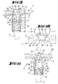
- the switch lock illustrated in FIGS. 1 to 8 is as a whole with the number 1 designated. It has a fastening element 2, which acts as a fastening plate is trained. It has a rectangular layout with through holes at the end 3 to the switch lock 1 on the upper horizontal To be able to fasten the fold of a door, not shown. center goes from the mounting plate or the fastener 2, a guide sleeve 4 out. Its diameter is smaller than the width of the mounting plate 2.
- the inner diameter of the guide sleeve 4 is the outer diameter a drive rod 5 adapted. A feather not illustrated loads them in the upward direction, i.e. in the direction of advance.
- the top end 5 ' the drive rod 5 is frustoconical.
- the compression spring 7 in question encompasses the lower end of the guide sleeve 4 and is supported there on an outward facing collar 8.
- the sensing element 6 forms two clamping jaws 9, 10 which can be moved relative to one another out.
- Each jaw 9, 10 is bowl-shaped.
- the top of the as Compression spring 7 designed compression spring 7 acts on the two jaws 9, 10 in the direction of advance.
- the stop limit will be given to the Jaws 9, 10 each by a stop rib 11, the upper end face is supported on the underside of the mounting plate 2, see in particular 2 and 5.
- the areas of the clamping jaws 9 projecting over the fastening plate 2 10 form trap slopes 12, which are up to an upper, rectangular Extend support surface 13.
- the outline of the floor plan seen from above the jaws 9, 10 are through openings 14, 15 of the mounting plate 2 adjusted. The latter are placed so that the two shells, i.e. the jaws 9, 10, are spaced apart from one another in the area of their trap slopes 12.
- the two clamping jaws 9, 10 it is possible for the two clamping jaws 9, 10 to move in the direction of the drive rod are movable relative to each other. For example one jaw can still stand while the other is already emotional.
- the cup-shaped jaws are 9, 10 on the outer surface of the guide sleeve 4 tongue / groove.
- To this Purpose forms each jaw 9, 10 grooves 16, in which in the longitudinal direction of the sleeve engage extending springs 17.
- Each jaw 9, 10 takes in a direction transverse to the jaw displacement direction extending opening 18 on a clamping plunger 19. So lie on one Diametrically two clamping plungers 19 opposite each other. The diametric runs in the longitudinal direction of the mounting plate 2. In the middle each clamping plunger 19 a collar 20, which with a limited axial stroke in both Chamber 18 'of the jaw 9, 10 rests. The chamber 18 'is formed by a widening of the opening 18. The inner end of the clamping plunger 19 protrudes into a guide slot running in the longitudinal direction of the guide sleeve 4 21 of the guide sleeve 4. There the clamping plunger 19 forms a spherically shaped Clamping surface 22.
- the opposite end of the clamping plunger 19 is closed formed a control surface 23 which has an edge-side control cone 24.
- This control cone 24 acts with an edge of the passage opening 14, 15 of the mounting plate 2 together, see FIGS. 3 and 6. This corresponds of the jaws 9, 10 displaced in the blocking direction.
- the edges 14 'or 15' the control cone 24 is acted on, so that the clamping surfaces 22 protrude into the inner cavity of the guide sleeve 4. Therefore this is supported upper end 5 'of the drive rod 5 on the clamping plungers 19 and can not in to step forward.
- each clamping plunger 19 is less than the height of the control cone 24, so that even with displaced jaws 9, 10 it is ensured that this can move back to their intended position of priority.
- the guide slots 21 of the guide sleeve 4 Form end extensions 25.
- the latter are circular designed and have a diameter that is slightly larger than that of the middle collar 20. So that the clamping plunger 19 at the level of the mounting extensions 25 can get, the jaws 9, 10 around such a measure that is larger than that of a normal one Impingement. As a result, the chamber 18 'comes into alignment to widen the assembly 25, which allows the subsequent insertion of a clamping plunger 19. During the subsequent shift of the jaw, 9, 10 extends then the middle collar 20 on the jacket wall side of the guide sleeve 4. The end of the clamping plunger which exclusively forms the clamping surface 22 19 protrudes into the guide slot 21.
- the opening of the key switch 1 requires a relocation of the Driving rod 5 against spring action. After this the closing recess 27 has left, the door can be opened, whereupon the clamping jaw spring 7 can take effect and the jaws 9, 10 in their forward position relocated.
- the plungers 19 are on the control surfaces 23 and counter-control surfaces 14 ', 15' in the sleeve inward direction, so that the clamping surfaces 22 again in front of the upper end 5 ' Drive rod 5 lie and block their exit shift.
- the second embodiment of the switch lock 1 ' according to FIGS. 9 to 11 carries the plate-shaped fastener 2, the guide sleeve 4.
- Das Stylus 6 also has two jaws 30, 31. These are in contrast to the first embodiment guided inside the sleeve.
- the Jaws 30, 31 At their ends protruding the mounting plate 2 form the Jaws 30, 31 the trap slopes 12.
- the two clamping jaws 30, 31 are pivotable on that of the bevel 12 coupled end coupled together. For this purpose go from the Edge edges of the cup-shaped jaws 30, 31 coupling projections 34, 35, which interlock.
- the coupling protrusions 34, 35 on the relevant edge edges of the clamping jaws 30, 31 are arranged that a longitudinal displacement of the jaws 30, 31 relative to each other not possible. There can only be a swiveling movement of the Jaws 30, 31 can be reached to each other.
- each jaw 30, 31 forms a control flank 36, which with Counter flanks 37 cooperate in the form of edges.
- the counter flanks are formed 37 from the edges of the passage openings 14, 15. Because of that the braking surfaces run at their leading position Clamping jaws 30, 31, which represent the sensing element 6, converging towards one another, see Fig. 9.
- the forward shifting of the clamping jaws is limited 30, 31 through a radial web 38 of the mounting plate 2, on which the underside Support stop shoulders 39 of the jaws 30, 31, see FIG. 9.
- each jaw 30, 31 forms a guide flank 40, which cooperates with the radial web 38 and in inward displacement the jaws 30, 31 controls them away from each other.
- This inner guide flanks 40 are the edge edges of the shells Assigned jaws 30, 31.
- One jaw 31 forms a projection 41 at its lower end, which protrudes into a guide slot 42 of the guide sleeve 4.
Abstract
Description
- Fig. 1
- eine Ansicht eines erfindungsgemäß gestalteten Schaltschlosses, betreffend die erste Ausführungsform in unverriegeltem Zustand,
- Fig. 2
- eine Seitenansicht der Fig. 1,
- Fig. 3
- den Schnitt nach der Linie III-III in Fig. 2, vergrößert dargestellt,
- Fig. 4
- den Schnitt nach der Linie IV-IV in Fig. 1, ebenfalls vergrößert dargestellt,
- Fig. 5
- eine Draufsicht auf das Schaltschloss,
- Fig. 6
- in stark vergrößerter Darstellung einen Horizontalschnitt durch das Schaltschloss auf Höhe eines Klemmstößels,
- Fig. 7
- eine Darstellung wie Fig. 3, jedoch die Verriegelungsstellung betreffend,
- Fig. 8
- eine der Fig. 4 vergleichbare Darstellung, jedoch ebenfalls die Verriegelungsstellung des Schaltschlosses betreffend,
- Fig. 9
- einen Längsschnitt durch das Schaltschloss gemäß der zweiten Ausführungsform in Freigabestellung der Treibstange,
- Fig. 10
- eine Draufsicht auf das Schaltschloss und
- Fig. 11
- einen der Fig. 9 vergleichbaren Längsschnitt, jedoch in der Verriegelungsstellung des Schaltschlosses.
Claims (20)
- Schaltschloss für eine in einer Tür oder dergleichen in Austrittsrichtung federbeaufschlagt geführte, eine Sperrstellung und eine Freigabestellung einnehmende Treibstange (5), mit einer die Treibstange (5) führenden Führungshülse (4) mit einem falzseitig an der Tür zu befestigenden Befestigungselement (2), an welcher Führungshülse (4) ein in Auswärtsrichtung federbeaufschlagtes Tastorgan (6) geführt ist, wobei die Treibstange (5) in ihrer rückgeschlossenen Freigabestellung von dem in einer Vortrittsstellung befindlichen Tastorgan (6) bewegungsgehemmt ist, welche Bewegungshemmung durch Zurückverlagerung des Tastorgans (6) aus der Vortrittsstellung in eine Rücktrittsstellung aufhebbar ist, dadurch gekennzeichnet, dass das Tastorgan (6) zwei Klemmelemente, insbesondere in Form relativ zueinander bewegbarer Klemmbacken (9, 10 bzw. 30, 31) ausbildet.
- Schaltschloss nach Anspruch 1 oder insbesondere danach, dadurch gekennzeichnet, dass jedes Klemmelement (9, 10 bzw. 30, 31) eine Schalenform besitzt.
- Schaltschloss nach einem oder mehreren der vorhergehenden Ansprüche oder insbesondere danach, dadurch gekennzeichnet, dass die beiden Klemmelemente (9, 10 bzw. 30, 31) von einer gemeinsamen Klemmbackenfeder (7 bzw. 33) in die Vortrittsstellung beaufschlagt sind.
- Schaltschloss nach einem oder mehreren der vorhergehenden Ansprüche oder insbesondere danach, dadurch gekennzeichnet, dass die beiden als Schalen ausgebildete Klemmelemente zumindest im Bereich ihrer Fallenschrägen (12) voneinander beabstandet sind.
- Schaltschloss nach einem oder mehreren der vorhergehenden Ansprüche oder insbesondere danach, dadurch gekennzeichnet, dass die beiden Klemmelemente (9, 10) in Treibstangen-Verlagerungsrichtung relativ zueinander bewegbar sind.
- Schaltschloss nach einem oder mehreren der vorhergehenden Ansprüche oder insbesondere danach, dadurch gekennzeichnet, dass jedes Klemmelement (9, 10) ein in einer Öffnung (18) des Klemmelementes (9, 10) quer zur Klemmelement-Verlagerungsrichtung und in einem Führungsschlitz (21) der Führungshülse (4) geführten Klemmstößel (19) aufweist, welcher mit seiner nach innen weisenden Klemmfläche (22) gegen die Treibstange (5) wirkt und mit seiner von der Klemmfläche (22) wegweisenden Steuerfläche (23) mit einer Gegensteuerfläche (14', 15') zusammenwirkt.
- Schaltschloss nach einem oder mehreren der vorhergehenden Ansprüche oder insbesondere danach, dadurch gekennzeichnet, dass die Gegensteuerfläche (14', 15') dem insbesondere als Befestigungsplatte ausgebildeten Befestigungselement (2) zugeordnet ist.
- Schaltschloss nach einem oder mehreren der vorhergehenden Ansprüche oder insbesondere danach, dadurch gekennzeichnet, dass die schalenförmigen Klemmbacken (9, 10) auf der Außenfläche der Führungshülse (4) nut/ federgeführt sind.
- Schaltschloss nach einem oder mehreren der vorhergehenden Ansprüche oder insbesondere danach, dadurch gekennzeichnet, dass der Klemmstößel (19) einen mittleren Kragen (20) aufweist, mit welchem er mit beiderseitig begrenztem Axialhub in einer Kammer (18') des Klemmelementes (9, 10) einliegt.
- Schaltschloss nach einem oder mehreren der vorhergehenden Ansprüche oder insbesondere danach, dadurch gekennzeichnet, dass die Klemmfläche (22) ballig ist.
- Schaltschloss nach einem oder mehreren der vorhergehenden Ansprüche oder insbesondere danach, dadurch gekennzeichnet, dass die Steuerfläche (23) einen randseitigen Steuerkonus (24) aufweist.
- Schaltschloss nach einem oder mehreren der vorhergehenden Ansprüche oder insbesondere danach, dadurch gekennzeichnet, dass der Steuerkonus (24) mit einer Kante (14', 15') oder Fläche einer Öffnung (14, 15) der Befestigungsplatte (2) zusammenwirkt.
- Schaltschloss nach einem oder mehreren der vorhergehenden Ansprüche oder insbesondere danach, gekennzeichnet durch den Führungsschlitzen (21) der Führungshülse (4) endseitig zugeordnete Montageverbreiterungen (25) zum Einsetzen der Klemmstößel (19).
- Schaltschloss nach einem oder mehreren der vorhergehenden Ansprüche oder insbesondere danach, dadurch gekennzeichnet, dass die beiden Klemmelemente (30, 31) in Richtung aufeinander zu relativ zueinander insbesondere schwenkbewegbar sind.
- Schaltschloss nach einem oder mehreren der vorhergehenden Ansprüche oder insbesondere danach, dadurch gekennzeichnet, dass die beiden Klemmelemente (30, 31) in der Vortrittsstellung spitzwinklig zueinander stehen und mit ihren Innenwandungen Klemmflächen für die Treibstange (5) ausbilden.
- Schaltschloss nach einem oder mehreren der vorhergehenden Ansprüche oder insbesondere danach, dadurch gekennzeichnet, dass die beiden Klemmelemente (30, 31) schwenkbar an dem der Fallenschräge (12) abgekehrten Ende aneinander gekuppelt sind.
- Schaltschloss nach einem oder mehreren der vorhergehenden Ansprüche oder insbesondere danach, dadurch gekennzeichnet, dass die Klemmelemente (30, 31) hülseninnenseitig geführt sind.
- Schaltschloss nach einem oder mehreren der vorhergehenden Ansprüche oder insbesondere danach, dadurch gekennzeichnet, dass die Klemmelemente (30, 31) außenseitig eine Steuerflanke (36) ausbilden, die mit Gegenflanken (14', 15') in Form von Kanten oder Flächen der Befestigungsplatte (2) zusammenwirken.
- Schaltschloss nach einem oder mehreren der vorhergehenden Ansprüche oder insbesondere danach, gekennzeichnet durch innere Führungsflanken (40) zum Wegsteuern der Klemmelemente (30, 31) voneinander beim Verlagern derselben in die Rücktrittsstellung.
- Schaltschloss nach einem oder mehreren der vorhergehenden Ansprüche oder insbesondere danach, dadurch gekennzeichnet, dass die inneren Führungsflanken (40) den Randkanten der als Schalen ausgebildeten Klemmelemente (30, 31) zugeordnet sind.
Applications Claiming Priority (2)
| Application Number | Priority Date | Filing Date | Title |
|---|---|---|---|
| DE2003118352 DE10318352B3 (de) | 2003-04-23 | 2003-04-23 | Schaltschloss für eine in einer Tür geführte Treibstange |
| DE10318352 | 2003-04-23 |
Publications (2)
| Publication Number | Publication Date |
|---|---|
| EP1475495A2 true EP1475495A2 (de) | 2004-11-10 |
| EP1475495A3 EP1475495A3 (de) | 2007-12-19 |
Family
ID=32981135
Family Applications (1)
| Application Number | Title | Priority Date | Filing Date |
|---|---|---|---|
| EP04101598A Withdrawn EP1475495A3 (de) | 2003-04-23 | 2004-04-19 | Schaltschloss für eine in einer Tür geführte Treibstange |
Country Status (2)
| Country | Link |
|---|---|
| EP (1) | EP1475495A3 (de) |
| DE (1) | DE10318352B3 (de) |
Cited By (5)
| Publication number | Priority date | Publication date | Assignee | Title |
|---|---|---|---|---|
| CH704792A3 (de) * | 2012-07-20 | 2012-10-15 | Jegen Ag | Verriegelungsvorrichtung und Tür, der eine solche Verriegelungsvorrichtung zugeordnet ist. |
| WO2015189783A3 (en) * | 2014-06-10 | 2016-04-21 | Masterlab S.R.L. Unipersonale | Closing device for closing door-leafs of doors or windows |
| EP2754801B1 (de) | 2013-01-11 | 2016-10-12 | Wilh. Schlechtendahl & Söhne GmbH & Co. KG | Gegenkasten oder Einsteckschloss |
| WO2021152641A1 (en) * | 2020-01-28 | 2021-08-05 | Cisa S.P.A. | Locking assembly for latches |
| EP3916179A1 (de) | 2020-05-27 | 2021-12-01 | dormakaba Deutschland GmbH | Schlossanordnung |
Citations (4)
| Publication number | Priority date | Publication date | Assignee | Title |
|---|---|---|---|---|
| EP0348971A2 (de) | 1988-07-01 | 1990-01-03 | BKS GmbH | Treibriegel-Schaltschloss, insbesondere für Treibstangenverschlüsse an Tür- od.dgl.-Flügeln |
| EP0732427A2 (de) | 1995-03-16 | 1996-09-18 | Sumitomo Electric Industries, Limited | Verfahren und Vorrichtung zur Züchtung eines Einkristalles |
| EP0859106A1 (de) | 1997-02-17 | 1998-08-19 | Talleres De Escoriaza, S.A. (TESA) | Obere und untere Verschlussstellenvorrichtung für Türe mit automatischem Schloss |
| DE19727365C1 (de) | 1997-06-27 | 1998-10-22 | Schlechtendahl & Soehne Wilh | Schaltschloß für eine Treibstange in einer Tür oder dergl. |
Family Cites Families (3)
| Publication number | Priority date | Publication date | Assignee | Title |
|---|---|---|---|---|
| DE2912881A1 (de) * | 1979-03-30 | 1980-10-09 | Scovill Sicherheitseinrichtung | Treibstangenverschluss, insbesondere fuer zweifluegelige feuerschutztueren |
| IT232093Y1 (it) * | 1994-11-21 | 1999-08-16 | Corbin Co | Dispositivo perfezionato per il bloccaggio dell'asta di chiusura di porte di sicurezza |
| IT238933Y1 (it) * | 1995-03-16 | 2001-02-19 | Italiana Serrature Affini | Perfezionamento a un dispositivo per bloccare i chiavistelli in unaporta di sicurezza |
-
2003
- 2003-04-23 DE DE2003118352 patent/DE10318352B3/de not_active Expired - Fee Related
-
2004
- 2004-04-19 EP EP04101598A patent/EP1475495A3/de not_active Withdrawn
Patent Citations (4)
| Publication number | Priority date | Publication date | Assignee | Title |
|---|---|---|---|---|
| EP0348971A2 (de) | 1988-07-01 | 1990-01-03 | BKS GmbH | Treibriegel-Schaltschloss, insbesondere für Treibstangenverschlüsse an Tür- od.dgl.-Flügeln |
| EP0732427A2 (de) | 1995-03-16 | 1996-09-18 | Sumitomo Electric Industries, Limited | Verfahren und Vorrichtung zur Züchtung eines Einkristalles |
| EP0859106A1 (de) | 1997-02-17 | 1998-08-19 | Talleres De Escoriaza, S.A. (TESA) | Obere und untere Verschlussstellenvorrichtung für Türe mit automatischem Schloss |
| DE19727365C1 (de) | 1997-06-27 | 1998-10-22 | Schlechtendahl & Soehne Wilh | Schaltschloß für eine Treibstange in einer Tür oder dergl. |
Cited By (6)
| Publication number | Priority date | Publication date | Assignee | Title |
|---|---|---|---|---|
| CH704792A3 (de) * | 2012-07-20 | 2012-10-15 | Jegen Ag | Verriegelungsvorrichtung und Tür, der eine solche Verriegelungsvorrichtung zugeordnet ist. |
| EP2754801B1 (de) | 2013-01-11 | 2016-10-12 | Wilh. Schlechtendahl & Söhne GmbH & Co. KG | Gegenkasten oder Einsteckschloss |
| EP2754801B2 (de) † | 2013-01-11 | 2019-07-10 | Wilh. Schlechtendahl & Söhne GmbH & Co. KG | Gegenkasten oder Einsteckschloss |
| WO2015189783A3 (en) * | 2014-06-10 | 2016-04-21 | Masterlab S.R.L. Unipersonale | Closing device for closing door-leafs of doors or windows |
| WO2021152641A1 (en) * | 2020-01-28 | 2021-08-05 | Cisa S.P.A. | Locking assembly for latches |
| EP3916179A1 (de) | 2020-05-27 | 2021-12-01 | dormakaba Deutschland GmbH | Schlossanordnung |
Also Published As
| Publication number | Publication date |
|---|---|
| DE10318352B3 (de) | 2004-10-14 |
| EP1475495A3 (de) | 2007-12-19 |
Similar Documents
| Publication | Publication Date | Title |
|---|---|---|
| DE102006037494B4 (de) | Türschließvorrichtung für ein elektrisches Haushaltsgerät, insbesondere eine Geschirrspülmschine | |
| EP1743994B1 (de) | Fluchttürschloss | |
| EP1688566B1 (de) | Schloss mit Schwenkauslöser | |
| DE69815573T2 (de) | Schlossbeschlag für Schiebetür, Schiebefenster oder ähnliches | |
| EP1526236A2 (de) | Vorrichtung zum Verriegeln und zum Betätigen von Klappen, Türen oder dgl. | |
| EP0677634B1 (de) | Insbesondere an Wohnungsabschlusstüren einzusetzendes Schloss, insbesondere Treibstangenschloss | |
| DE3425565A1 (de) | Treibstangenschloss | |
| DE19506106C2 (de) | Beschlag für Fenster, Türen od. dgl. | |
| EP1475495A2 (de) | Schaltschloss für eine in einer Tür geführten Treibstange | |
| DE4204317A1 (de) | Tuerdrueckergarnitur | |
| EP2156060B1 (de) | Befestiger zum lösbaren verbinden eines profils an ein gegenprofil | |
| DE102008034070A1 (de) | Schließzylinder mit federkraftunterstützter Zylinderkernrückstellung | |
| EP0606877B1 (de) | Beschlag für ein eine Falle und einen Riegel aufweisendes Schloss | |
| DE102017100149B4 (de) | Automatische Türspaltdichtung | |
| DE3735042C2 (de) | Schließvorrichtung für Koffer, Taschen oder dergleichen | |
| EP0874118B1 (de) | Gegenschloss für Nottüren mit Doppelflügeln und einer Antipanik-Öffnung | |
| DE3825823C2 (de) | ||
| DE19929103B4 (de) | Verschluss für Türen, Hauben, Klappen od.dgl., insbesondere Heckverschluss eines Fahrzeugs | |
| DE19801300A1 (de) | Versenkbare Drehknebeleinheit | |
| DE4117354C2 (de) | Drehstangenschloß | |
| DE3734695A1 (de) | Verschlussvorrichtung fuer koffer, taschen, insbesondere aktenkoffer oder dergleichen | |
| DE102009003875B3 (de) | Verschlusssystem für ein Möbel mit mindestens zwei Schiebetüren und Verfahren zum Verschließen eines Möbels | |
| DE19504718C2 (de) | Schließeinrichtung für ein öffenbares Möbelteil | |
| CH446949A (de) | Treibstangenverschluss | |
| EP4264096A1 (de) | Betätigungsvorrichtung zur verwendung in sanitärinstallationen |
Legal Events
| Date | Code | Title | Description |
|---|---|---|---|
| PUAI | Public reference made under article 153(3) epc to a published international application that has entered the european phase |
Free format text: ORIGINAL CODE: 0009012 |
|
| AK | Designated contracting states |
Kind code of ref document: A2 Designated state(s): AT BE BG CH CY CZ DE DK EE ES FI FR GB GR HU IE IT LI LU MC NL PL PT RO SE SI SK TR |
|
| AX | Request for extension of the european patent |
Extension state: AL HR LT LV MK |
|
| PUAL | Search report despatched |
Free format text: ORIGINAL CODE: 0009013 |
|
| AK | Designated contracting states |
Kind code of ref document: A3 Designated state(s): AT BE BG CH CY CZ DE DK EE ES FI FR GB GR HU IE IT LI LU MC NL PL PT RO SE SI SK TR |
|
| AX | Request for extension of the european patent |
Extension state: AL HR LT LV MK |
|
| 17P | Request for examination filed |
Effective date: 20080312 |
|
| AKX | Designation fees paid |
Designated state(s): AT CH DE FR IT LI |
|
| 17Q | First examination report despatched |
Effective date: 20090909 |
|
| STAA | Information on the status of an ep patent application or granted ep patent |
Free format text: STATUS: THE APPLICATION IS DEEMED TO BE WITHDRAWN |
|
| 18D | Application deemed to be withdrawn |
Effective date: 20151031 |