EP1475314A1 - Behälter mit Deckel - Google Patents
Behälter mit Deckel Download PDFInfo
- Publication number
- EP1475314A1 EP1475314A1 EP03010270A EP03010270A EP1475314A1 EP 1475314 A1 EP1475314 A1 EP 1475314A1 EP 03010270 A EP03010270 A EP 03010270A EP 03010270 A EP03010270 A EP 03010270A EP 1475314 A1 EP1475314 A1 EP 1475314A1
- Authority
- EP
- European Patent Office
- Prior art keywords
- container
- collar
- edge
- container according
- opening
- Prior art date
- Legal status (The legal status is an assumption and is not a legal conclusion. Google has not performed a legal analysis and makes no representation as to the accuracy of the status listed.)
- Granted
Links
- 239000007787 solid Substances 0.000 claims abstract description 4
- 235000013305 food Nutrition 0.000 claims description 3
- 235000011837 pasties Nutrition 0.000 claims description 3
- 230000009969 flowable effect Effects 0.000 claims 1
- 238000000034 method Methods 0.000 description 12
- 239000011888 foil Substances 0.000 description 8
- 239000000463 material Substances 0.000 description 6
- 210000003811 finger Anatomy 0.000 description 4
- 230000000694 effects Effects 0.000 description 3
- 238000004519 manufacturing process Methods 0.000 description 3
- 210000003813 thumb Anatomy 0.000 description 3
- 230000015572 biosynthetic process Effects 0.000 description 2
- 235000013351 cheese Nutrition 0.000 description 2
- 235000013365 dairy product Nutrition 0.000 description 2
- 230000004927 fusion Effects 0.000 description 2
- 238000002347 injection Methods 0.000 description 2
- 239000007924 injection Substances 0.000 description 2
- 238000001746 injection moulding Methods 0.000 description 2
- 210000004185 liver Anatomy 0.000 description 2
- 235000015250 liver sausages Nutrition 0.000 description 2
- 238000004806 packaging method and process Methods 0.000 description 2
- 239000000243 solution Substances 0.000 description 2
- 230000008093 supporting effect Effects 0.000 description 2
- 230000003313 weakening effect Effects 0.000 description 2
- 238000003466 welding Methods 0.000 description 2
- 235000013618 yogurt Nutrition 0.000 description 2
- XAGFODPZIPBFFR-UHFFFAOYSA-N aluminium Chemical compound [Al] XAGFODPZIPBFFR-UHFFFAOYSA-N 0.000 description 1
- 229910052782 aluminium Inorganic materials 0.000 description 1
- 230000009286 beneficial effect Effects 0.000 description 1
- 235000014121 butter Nutrition 0.000 description 1
- 150000001875 compounds Chemical class 0.000 description 1
- 238000010276 construction Methods 0.000 description 1
- 230000001066 destructive effect Effects 0.000 description 1
- 210000003746 feather Anatomy 0.000 description 1
- 235000013569 fruit product Nutrition 0.000 description 1
- 230000036512 infertility Effects 0.000 description 1
- 235000013372 meat Nutrition 0.000 description 1
- 235000013622 meat product Nutrition 0.000 description 1
- 235000019690 meat sausages Nutrition 0.000 description 1
- 239000000203 mixture Substances 0.000 description 1
- 230000002093 peripheral effect Effects 0.000 description 1
- 235000015504 ready meals Nutrition 0.000 description 1
- 238000005096 rolling process Methods 0.000 description 1
- 235000013580 sausages Nutrition 0.000 description 1
- 238000007789 sealing Methods 0.000 description 1
- 235000013311 vegetables Nutrition 0.000 description 1
Images
Classifications
-
- B—PERFORMING OPERATIONS; TRANSPORTING
- B65—CONVEYING; PACKING; STORING; HANDLING THIN OR FILAMENTARY MATERIAL
- B65D—CONTAINERS FOR STORAGE OR TRANSPORT OF ARTICLES OR MATERIALS, e.g. BAGS, BARRELS, BOTTLES, BOXES, CANS, CARTONS, CRATES, DRUMS, JARS, TANKS, HOPPERS, FORWARDING CONTAINERS; ACCESSORIES, CLOSURES, OR FITTINGS THEREFOR; PACKAGING ELEMENTS; PACKAGES
- B65D43/00—Lids or covers for rigid or semi-rigid containers
- B65D43/02—Removable lids or covers
- B65D43/0202—Removable lids or covers without integral tamper element
- B65D43/0214—Removable lids or covers without integral tamper element secured only by friction or gravity
-
- B—PERFORMING OPERATIONS; TRANSPORTING
- B65—CONVEYING; PACKING; STORING; HANDLING THIN OR FILAMENTARY MATERIAL
- B65D—CONTAINERS FOR STORAGE OR TRANSPORT OF ARTICLES OR MATERIALS, e.g. BAGS, BARRELS, BOTTLES, BOXES, CANS, CARTONS, CRATES, DRUMS, JARS, TANKS, HOPPERS, FORWARDING CONTAINERS; ACCESSORIES, CLOSURES, OR FITTINGS THEREFOR; PACKAGING ELEMENTS; PACKAGES
- B65D51/00—Closures not otherwise provided for
- B65D51/18—Arrangements of closures with protective outer cap-like covers or of two or more co-operating closures
- B65D51/185—Arrangements of closures with protective outer cap-like covers or of two or more co-operating closures the outer closure being a foil membrane
-
- B—PERFORMING OPERATIONS; TRANSPORTING
- B65—CONVEYING; PACKING; STORING; HANDLING THIN OR FILAMENTARY MATERIAL
- B65D—CONTAINERS FOR STORAGE OR TRANSPORT OF ARTICLES OR MATERIALS, e.g. BAGS, BARRELS, BOTTLES, BOXES, CANS, CARTONS, CRATES, DRUMS, JARS, TANKS, HOPPERS, FORWARDING CONTAINERS; ACCESSORIES, CLOSURES, OR FITTINGS THEREFOR; PACKAGING ELEMENTS; PACKAGES
- B65D2251/00—Details relating to container closures
- B65D2251/0003—Two or more closures
- B65D2251/0006—Upper closure
- B65D2251/0031—Membrane
-
- B—PERFORMING OPERATIONS; TRANSPORTING
- B65—CONVEYING; PACKING; STORING; HANDLING THIN OR FILAMENTARY MATERIAL
- B65D—CONTAINERS FOR STORAGE OR TRANSPORT OF ARTICLES OR MATERIALS, e.g. BAGS, BARRELS, BOTTLES, BOXES, CANS, CARTONS, CRATES, DRUMS, JARS, TANKS, HOPPERS, FORWARDING CONTAINERS; ACCESSORIES, CLOSURES, OR FITTINGS THEREFOR; PACKAGING ELEMENTS; PACKAGES
- B65D2251/00—Details relating to container closures
- B65D2251/0003—Two or more closures
- B65D2251/0068—Lower closure
- B65D2251/0081—Lower closure of the 43-type
-
- B—PERFORMING OPERATIONS; TRANSPORTING
- B65—CONVEYING; PACKING; STORING; HANDLING THIN OR FILAMENTARY MATERIAL
- B65D—CONTAINERS FOR STORAGE OR TRANSPORT OF ARTICLES OR MATERIALS, e.g. BAGS, BARRELS, BOTTLES, BOXES, CANS, CARTONS, CRATES, DRUMS, JARS, TANKS, HOPPERS, FORWARDING CONTAINERS; ACCESSORIES, CLOSURES, OR FITTINGS THEREFOR; PACKAGING ELEMENTS; PACKAGES
- B65D2543/00—Lids or covers essentially for box-like containers
- B65D2543/00009—Details of lids or covers for rigid or semi-rigid containers
- B65D2543/00018—Overall construction of the lid
- B65D2543/00064—Shape of the outer periphery
- B65D2543/0012—Shape of the outer periphery having straight sides, e.g. with curved corners
- B65D2543/00175—Shape of the outer periphery having straight sides, e.g. with curved corners four straight sides, e.g. trapezium or diamond
- B65D2543/00194—Shape of the outer periphery having straight sides, e.g. with curved corners four straight sides, e.g. trapezium or diamond square or rectangular
-
- B—PERFORMING OPERATIONS; TRANSPORTING
- B65—CONVEYING; PACKING; STORING; HANDLING THIN OR FILAMENTARY MATERIAL
- B65D—CONTAINERS FOR STORAGE OR TRANSPORT OF ARTICLES OR MATERIALS, e.g. BAGS, BARRELS, BOTTLES, BOXES, CANS, CARTONS, CRATES, DRUMS, JARS, TANKS, HOPPERS, FORWARDING CONTAINERS; ACCESSORIES, CLOSURES, OR FITTINGS THEREFOR; PACKAGING ELEMENTS; PACKAGES
- B65D2543/00—Lids or covers essentially for box-like containers
- B65D2543/00009—Details of lids or covers for rigid or semi-rigid containers
- B65D2543/00018—Overall construction of the lid
- B65D2543/00259—Materials used
- B65D2543/00296—Plastic
-
- B—PERFORMING OPERATIONS; TRANSPORTING
- B65—CONVEYING; PACKING; STORING; HANDLING THIN OR FILAMENTARY MATERIAL
- B65D—CONTAINERS FOR STORAGE OR TRANSPORT OF ARTICLES OR MATERIALS, e.g. BAGS, BARRELS, BOTTLES, BOXES, CANS, CARTONS, CRATES, DRUMS, JARS, TANKS, HOPPERS, FORWARDING CONTAINERS; ACCESSORIES, CLOSURES, OR FITTINGS THEREFOR; PACKAGING ELEMENTS; PACKAGES
- B65D2543/00—Lids or covers essentially for box-like containers
- B65D2543/00009—Details of lids or covers for rigid or semi-rigid containers
- B65D2543/00444—Contact between the container and the lid
- B65D2543/00453—Contact between the container and the lid in a peripheral U-shaped channel of the container
-
- B—PERFORMING OPERATIONS; TRANSPORTING
- B65—CONVEYING; PACKING; STORING; HANDLING THIN OR FILAMENTARY MATERIAL
- B65D—CONTAINERS FOR STORAGE OR TRANSPORT OF ARTICLES OR MATERIALS, e.g. BAGS, BARRELS, BOTTLES, BOXES, CANS, CARTONS, CRATES, DRUMS, JARS, TANKS, HOPPERS, FORWARDING CONTAINERS; ACCESSORIES, CLOSURES, OR FITTINGS THEREFOR; PACKAGING ELEMENTS; PACKAGES
- B65D2543/00—Lids or covers essentially for box-like containers
- B65D2543/00009—Details of lids or covers for rigid or semi-rigid containers
- B65D2543/00444—Contact between the container and the lid
- B65D2543/00481—Contact between the container and the lid on the inside or the outside of the container
- B65D2543/0049—Contact between the container and the lid on the inside or the outside of the container on the inside, or a part turned to the inside of the mouth of the container
- B65D2543/00518—Skirt
-
- B—PERFORMING OPERATIONS; TRANSPORTING
- B65—CONVEYING; PACKING; STORING; HANDLING THIN OR FILAMENTARY MATERIAL
- B65D—CONTAINERS FOR STORAGE OR TRANSPORT OF ARTICLES OR MATERIALS, e.g. BAGS, BARRELS, BOTTLES, BOXES, CANS, CARTONS, CRATES, DRUMS, JARS, TANKS, HOPPERS, FORWARDING CONTAINERS; ACCESSORIES, CLOSURES, OR FITTINGS THEREFOR; PACKAGING ELEMENTS; PACKAGES
- B65D2543/00—Lids or covers essentially for box-like containers
- B65D2543/00009—Details of lids or covers for rigid or semi-rigid containers
- B65D2543/00444—Contact between the container and the lid
- B65D2543/00481—Contact between the container and the lid on the inside or the outside of the container
- B65D2543/00537—Contact between the container and the lid on the inside or the outside of the container on the outside, or a part turned to the outside of the mouth of the container
- B65D2543/00546—NO contact
-
- B—PERFORMING OPERATIONS; TRANSPORTING
- B65—CONVEYING; PACKING; STORING; HANDLING THIN OR FILAMENTARY MATERIAL
- B65D—CONTAINERS FOR STORAGE OR TRANSPORT OF ARTICLES OR MATERIALS, e.g. BAGS, BARRELS, BOTTLES, BOXES, CANS, CARTONS, CRATES, DRUMS, JARS, TANKS, HOPPERS, FORWARDING CONTAINERS; ACCESSORIES, CLOSURES, OR FITTINGS THEREFOR; PACKAGING ELEMENTS; PACKAGES
- B65D2543/00—Lids or covers essentially for box-like containers
- B65D2543/00009—Details of lids or covers for rigid or semi-rigid containers
- B65D2543/00824—Means for facilitating removing of the closure
- B65D2543/00833—Integral tabs, tongues, handles or similar
- B65D2543/00842—Integral tabs, tongues, handles or similar outside of the lid
-
- B—PERFORMING OPERATIONS; TRANSPORTING
- B65—CONVEYING; PACKING; STORING; HANDLING THIN OR FILAMENTARY MATERIAL
- B65D—CONTAINERS FOR STORAGE OR TRANSPORT OF ARTICLES OR MATERIALS, e.g. BAGS, BARRELS, BOTTLES, BOXES, CANS, CARTONS, CRATES, DRUMS, JARS, TANKS, HOPPERS, FORWARDING CONTAINERS; ACCESSORIES, CLOSURES, OR FITTINGS THEREFOR; PACKAGING ELEMENTS; PACKAGES
- B65D2543/00—Lids or covers essentially for box-like containers
- B65D2543/00009—Details of lids or covers for rigid or semi-rigid containers
- B65D2543/00824—Means for facilitating removing of the closure
- B65D2543/00944—Located only on the container, e.g. recesses
Definitions
- the invention relates to a container for solid, pasty as well as free-flowing and pourable products, especially for Food products comprising a container bottom for receiving the product as well as a container lid trained container top, wherein on the container top one of these for opening the container with the upper part removable container bottom detachable Foil is attached.
- Such containers which are usually made of a plastic material exist and usually by means of known Injection molding techniques are made for the various uses and in the most diverse Sizes in the trade and are in the most diverse shapes for all sorts of hygienic products or germ-free packaging used. Products, the example. In such containers added as Verpakkungsakuen be presented in grocery stores, are, for example, dairy products of all kinds, meat and meat Sausage products, but also vegetables and fruit products as well Ready meals in chilled and uncooled form.
- the separate labels have the disadvantage that they make the production of the container considerably more expensive because of the Container then after filling the product and closing of the container, the label either on the container itself, the container lid or possibly on the container lid and the actual container got to.
- a third variant of containers is known in which a in the course of the production of the container lid after the method of the so-called "Immolded Label (IML)" produced Lid in the injection mold already with the foil, which forms the outer end of the container lid, is connected and beyond the container lid elaboratendr Edge region of the film connected to the container becomes.
- IML Immolded Label
- Even such containers show the serious Disadvantage that in the edge region of the container lid Reinforced label or the film uncontrolled when Opening the container tears or tears and over also by the notch effect when tearing between Foil and container lid, despite the use of Technique according to the "Immolded Label” method, the film from the container lid tears uncontrollably and the container only with foreign tools such as a pair of scissors or a Knife can be opened.
- the Disadvantages of known in the art containers does not have this type, i. which open easily leaves and in which a tearing of the film when opening the Container lid is avoided by the container base and the container lid when opening by detecting the Foil and the release of the container lid or container upper part from the bottom of the container is not damaged so that the container lid, if not airtight, but at least a closure of the container base can form if the product after the first Opening the container has not been completely removed is, the container is light and very inexpensive should be produced and thus for the most diverse Packaging can be provided inexpensively should be.
- the invention in that the container top a closed to its container opening running around, raised prominent edge has, on which the container upper part releasably secured is.
- the solution according to the invention has the extraordinary Advantage that the container upper part provided with a foil, which forms the container lid, defined by the invention trained, raised prominent edge the container base can be solved and exclusively the dimension of the raised protruding edge the attachment zone between container top and Container bottom part forms.
- This can be advantageous be dimensioned such that, depending on the nature of the material the container top and the container base and on the container top or the container lid attached foil, tearing open when opening the container or rolling the film is avoided and also by defined release of the connection between Tank shell and tank bottom a tearing of the Container upper part during the opening process and thus becoming unusable of the container top or container lid is avoided.
- the connection area between Container upper part and lower container part also requires by the very connection-effective nature of the constructive Design nevertheless no separate, elaborate Tools, so that the container itself with in the state of Technique known standard plastic injection molding can be produced and therefore also for this reason is extremely inexpensive to provide.
- edge in cross section in the manner of a spring trained, in the sense of a spring, as in a tongue and groove connection is used.
- the edge, for making the connection with the container shell is used by the upper surface of the spring formed as regularly parallel to the tank shell will be trained.
- the defined surface side creates the actual defined connection point with the container upper part.
- the container has the container bottom in the area of his Container opening a flange-like first Collar on which the protruding edge or the above Spring is formed.
- the first collar is formed in such a way that he is substantially perpendicular from the container base projects. In this way, the above-described Supporting effect of the container shell on the container base supported in a simple manner advantageously.
- the container base has a second collar on, at the free end of the first Collar is arranged and substantially rectangular sticking out from the first collar.
- the second collar at least one extending into the region of the first collar recess on, by which in a simple way for the execution the opening process with the fingers of the user the container top part detected and from the container bottom can be solved.
- the container top is preferably as in formed essential element, but it was on it pointed out that depending on the container In principle, other configurations are included in the recorded product the container top are possible.
- a defined area of connection between tank top and container bottom is to create the container top preferably in its edge region with a circumferentially formed in the container top Recess to the entrance of the edge of the container base provided so that the depression, as it were defined Surface on the one hand and as a guide on the other hand, with the raised protruding edge of the container base can be joined together.
- Edge of the container base is also the recess after Type of groove formed in the sense of a tongue and groove connection, so that the groove of the recess with the spring of Container lower part leader or led interacts and even then, if the container once as intended has been opened, a sealing Closing is possible if the product after opening not completely removed from the container bottom has been.
- the container becomes the bottom of the recess only formed by the attached on the container top sheet, so that virtually the connection between the container shell and container bottom between the film of Container upper part and the material of the edge of the container base, regularly identical to the Material of the container base is formed.
- the container upper part of the connecting element or forms the connection area can be achieved that when opening the container upper part the film is extremely defined by the joint is detached with the container bottom parts, without that Container upper part or the container lid damaged becomes.
- This broadening also has the Advantage that this can be used to the outside Edge region of the container top, i. on this orbiting Strip adjacent to the depression, or it limits, at least two opposing ones To provide notches that as weakening or break points Act.
- This makes it possible when to open of the container, the container shell by the user For example, between finger and thumb is detected in the course of the opening process, the strip to buckle slightly can, along these wells, so that also by this measure in addition the probability the tearing of the film from the container top or Container lid is avoided.
- the film is finally designed such that these preferably in the area between the notches for formation a grip tab over the outer edge of the container top protrudes, so that the film on simple Way grabbed between a user's finger and thumb, slightly bent up and buckling of the tank top in the said notches in the opening direction the container top can be pulled and thus the Connection between tank top and tank bottom is solved defined.
- connection between tank top and tank bottom can be done in any suitable manner subject to the requirements of the connection effect, i.e. from the point of view of the intended Hygiene, sterility and tightness from the point of view of moisture and air.
- Many suitable connection methods can to be used. It is particularly advantageous but, the tank shell with the tank bottom to connect by a fusion welding, since this in a simple way a hygienic air and moisture-proof and also impermeable compound creates.
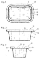
- the container 10 is the recording solid, pasty as well as free-flowing and pourable Products, in particular of food products.
- the container 10 includes the container base 11 for receiving of the product.
- Container 10 of this kind are, for example, by the all sides known yogurt cups made of plastic material or Also as a container for the inclusion of dairy products like butter, cheese, meat products, such as liver pate and Like. Used. In this respect, here, as the fundamental Construction of such container 10 is known, only on The details are given to help understand the invention are necessary.
- the container lower part 11 has a container opening 14 on.
- a flange circumferential first collar 17 is formed, the substantially perpendicular from the container base 11th protrudes, even if the container base 11 here a slightly protruding from a right angle, conical Container shape.
- the container upper part 11 a second collar 18 on the free End 19 of the first collar 17 is arranged and substantially protrudes at right angles from the first collar 17.
- the second collar 18, cf. Fig. 3 has a recess 20 on. This extends to the area of the first Collar 17 down. This recess 20 serves the Passage of a grip tab 28, cf. FIGS. 4 and 5, which will be discussed in detail below.
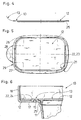
- the container top 12 is shown, that together with the container bottom part 11, which, as described before, shown in Figs. 1 to 3 is, the container 10 according to the invention forms.
- the tank shell 12 is provided with a film 13, the by the known principle of the so-called. "Immolded Label (IML) "during the plastic injection process with the container top 12 is connected.
- the tank shell 11 is formed substantially as a planar element, see. Fig. 4.
- the container upper part 12 has in its edge region 21st a circumferentially formed recess 22.
- the depression is formed in the manner of a groove 23.
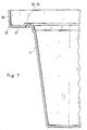
- the floor the recess 22, cf. Fig. 6, is of the on the container top 12 applied film 13 is formed.
- a web 25 is formed, cf. Figs. 4 and 6, in Direction of the container base 11 protrudes.
- the bridge 25 revolves the container top 12 at its bottom completely, as shown schematically in Fig. 4 is.
- the film 13 is provided with a grip tab 28, the made of the same material as the film 13 is and actually provides an extension of the film 13th over the peripheral edge region 21.
- This grip tab 28 is through the recess 20, see. Fig. 3, through (not shown there).
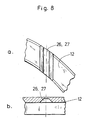
- the outer edge region of the container upper part 12, cf. also Fig. 6, extreme, there shown left Part of the container top 12, has at least two each other opposite notches 26, 27, cf. FIG. 5 and Figs. 8a and 8b, which is a detailed view the notches 26, 27 show.
- the container base 11 see. FIGS. 1 to 3 and 6 and 7, has a flange on the first collar 17th trained or raised by him before, or protruding Edge 15 up.
- the edge 15 is in cross section in the manner of a Spring 16 is formed, whereas the recess 22nd is formed in the manner of a groove 23, s.o.
- the floor 24 the recess 22 is, as already mentioned, by the said Slide 13 in the embodiment described here the container 10 is formed.
- the actual connection between the container top 12 and container base 11th takes place between the surface of the edge 15 and the Spring 16, the container top 12, at this point formed by the film 13, is directed towards.
- These Connection can be made in any suitable way, For example, by a fusion weld, by ultrasonic welding or any other suitable connection methods, possibly also using a separate Connection means.
- the container upper part 12 grasped at the grip tab 28 between finger and thumb, see. Figs. 4 and 5 and, based on the illustrations 4 and 5, moved to the right. Thereby then dissolves in the illustrated and described here Embodiment of the container 10, the container top 12 first of the narrow side of the container base 11, cf. Fig. 3, lifting, i. under solution the connection between the container and upper part 12 and lower container part 11 at this point and will, the farther the pull tab 28 is pulled to the right, over the entire area of the container opening 14 is lifted, whereby the container 10 is then opened.
- the notches 26, 27 facilitate the non-destructive Lifting the container shell 12, since this already a desired weakening for buckling of the container shell 12 is reached at these points, so that for relief the lifting of the container top 12 to the Notches 26, 27 takes place a kink effect.
- the tearing off the film 13 is thereby avoided on the one hand i.e. this also remains with the container top during the opening process 12 connected, and the edge 15 and the Recess 22 are not damaged, so that the container shell 12 below also for provisional closing the container opening 14 can be used if the product received in the container 10 is not completely removed after opening the container 10 has been.
Landscapes
- Engineering & Computer Science (AREA)
- Mechanical Engineering (AREA)
- Packages (AREA)
- Table Devices Or Equipment (AREA)
- Closures For Containers (AREA)
- Devices For Use In Laboratory Experiments (AREA)
- Details Of Rigid Or Semi-Rigid Containers (AREA)
- Packging For Living Organisms, Food Or Medicinal Products That Are Sensitive To Environmental Conditiond (AREA)
- Cookers (AREA)
- Food-Manufacturing Devices (AREA)
- Glass Compositions (AREA)
- Package Specialized In Special Use (AREA)
Abstract
Description
- Fig. 1
- in der Draufsicht ein Behälterunterteil,
- Fig. 2
- in der Seitenansicht ein Behälterunterteil,
- Fig. 3
- in der Stirnansicht ein Behälterunterteil mit sichtbarer Aussparung für den Durchtritt einer Grifflasche (hier nicht dargestellt),
- Fig. 4
- in der Seitenansicht ein Behälteroberteil,
- Fig. 5
- das Behälterunterteil in der Ansicht der Fig. 4 von unten,
- Fig. 6
- ein Detail des Verschließbereiches des Behälteroberteils mit dem Behälterunterteil in vergrößertem Maßstab
- Fig. 7
- in vergrößertem Maßstab ein Detail gem. Fig. 6, jedoch ohne Behälteroberteil, lediglich das Behälterunterteil darstellend,
- Fig. 8a
- ein Detail des Randbereiches des Behälteroberteils, eine Kerbung darstellend, und
- Fig. 8b
- eine Seitenansicht des Details gem. Fig. 8a.
- 10
- Behälter
- 11
- Behälterunterteil
- 12
- Behälteroberteil
- 13
- Folie
- 14
- Behälteröffnung
- 15
- Rand
- 16
- Feder
- 17
- erster Kragen
- 18
- zweiter Kragen
- 19
- freies Ende (erster Kragen)
- 20
- Aussparung
- 21
- Randbereich (Behälteroberteil)
- 22
- Vertiefung
- 23
- Nut
- 24
- Boden
- 25
- Steg
- 26
- Kerbung
- 27
- Kerbung
- 28
- Griffleiste
- 29
- äußerer Rand (Behälteroberteil)
Claims (14)
- Behälter (10) für feste, pastöse sowie fließ- und schöpffähige Produkte, insbesondere für Lebensmittelprodukte, umfassend ein Behälterunterteil (11) zur Aufnahme des Produkts sowie ein als Behälterdeckel ausgebildetes Behälteroberteil (12), wobei auf dem Behälteroberteil (12) eine von diesem zum Öffnen des mit dem Behälteroberteil (12) verschlossenen Behälterunterteils (11) ablösbare Folie (13) aufgebracht ist, dadurch gekennzeichnet, daß das Behälteroberteil (11) einen geschlossenen, um seine Behälteröffnung (14) herumlaufenden, erhaben vorstehenden Rand (15) aufweist, auf dem das Behälteroberteil (12) lösbar befestigt ist.
- Behälter nach Anspruch 1, dadurch gekennzeichnet, daß der Rand (15) im Querschnitt nach Art einer Feder (16) ausgebildet ist.
- Behälter nach einem oder beiden der Ansprüche 1 oder 2, dadurch gekennzeichnet, daß das Behälterunterteil (11) im Bereich seiner Behälteröffnung (14) einen flanschartig umlaufenden ersten Kragen (17) aufweist, auf dem der vorstehende Rand (15) ausgebildet ist.
- Behälte nach Anspruch 3, dadurch gekennzeichnet, daß der erste Kragen (17) im wesentlichen rechtwinkelig vom Behälterunterteil (11) absteht.
- Behälter nach einem oder beiden der Ansprüche 3 oder 4, dadurch gekennzeichnet, daß das Behälterunterteil (11) einen zweiten Kragen (18) aufweist, der am freien Ende (19) des ersten Kragens (17) angeordnet ist und im wesentlichen rechtwinkelig vom ersten Kragen (17) wegsteht.
- Behälter nach Anspruch 5, dadurch gekennzeichnet, daß der zweite Kragen (18) wenigstens eine sich bis in den Bereich des ersten Kragens (17) erstreckende Aussparung (20) aufweist.
- Behälter nach einem oder mehreren der Ansprüche 1 bis 6, dadurch gekennzeichnet, daß das Behälteroberteil (12) als im wesentlichen ebenes Element ausgebildet ist.
- Behälter nach einem oder mehreren der Ansprüche 1 bis 7, dadurch gekennzeichnet, daß im Behälteroberteil (12) in seinem Randbereich (21) eine im Behälteroberteil (12) umlaufend ausgebildete Vertiefung (22) zum Eintritt des Randes (15) des Behälterunterteils (11) ausgebildet ist.
- Behälter nach Anspruch 8, dadurch gekennzeichnet, daß die Vertiefung (22) nach Art einer Nut (23) ausgebildet ist.
- Behälter nach einem oder beiden der Ansprüche 8 oder 9, dadurch gekennzeichnet, daß der Boden (24) der Vertiefung (22) von der auf dem Behälteroberteil (12) aufgebrachten Folie (13) gebildet wird.
- Behälter nach einem oder mehreren der Ansprüche 1 bis 10, dadurch gekennzeichnet, daß das Behälteroberteil (12) einen zum Behälterunterteil (11) hin gerichteten, vorstehenden, umlaufenden Steg (25) aufweist.
- Behälter nach einem oder mehreren der Ansprüche 8 bis 11, dadurch gekennzeichnet, daß der äußere Randbereich (21) des Behälteroberteils (12), der an die Vertiefung (22) angrenzt, wenigstens zwei einander gegenüberliegende Kerbungen (26, 27) aufweist.
- Behälter nach Anspruch 12, dadurch gekennzeichnet, daß die Folie (13) im Bereich zwischen den Kerbungen (26, 27) zur Bildung einer Grifflasche (28) über dem äußeren Rand (29) des Behälteroberteils (12) hinaussteht.
- Behälter nach Anspruch 1, dadurch gekennzeichnet, daß das Behälteroberteil (12) mit dem Behälterunterteil (11) durch eine Schmelzschweißverbindung verbunden ist.
Priority Applications (11)
| Application Number | Priority Date | Filing Date | Title |
|---|---|---|---|
| DE50300867T DE50300867D1 (de) | 2003-05-07 | 2003-05-07 | Behälter mit Deckel |
| EP03010270A EP1475314B1 (de) | 2003-05-07 | 2003-05-07 | Behälter mit Deckel |
| ES03010270T ES2245754T3 (es) | 2003-05-07 | 2003-05-07 | Recipiente con tapa. |
| SI200330051T SI1475314T1 (en) | 2003-05-07 | 2003-05-07 | Container with lid |
| PT03010270T PT1475314E (pt) | 2003-05-07 | 2003-05-07 | Recipiente com tampa |
| AT03010270T ATE300482T1 (de) | 2003-05-07 | 2003-05-07 | Behälter mit deckel |
| DK03010270T DK1475314T3 (da) | 2003-05-07 | 2003-05-07 | Beholder med låg |
| CA002435066A CA2435066C (en) | 2003-05-07 | 2003-07-15 | Container |
| US10/637,809 US7267243B2 (en) | 2003-05-07 | 2003-08-08 | Container |
| RU2004108150/12A RU2294309C2 (ru) | 2003-05-07 | 2004-03-19 | Емкость |
| PL366600A PL207717B1 (pl) | 2003-05-07 | 2004-03-25 | Pojemnik |
Applications Claiming Priority (1)
| Application Number | Priority Date | Filing Date | Title |
|---|---|---|---|
| EP03010270A EP1475314B1 (de) | 2003-05-07 | 2003-05-07 | Behälter mit Deckel |
Publications (2)
| Publication Number | Publication Date |
|---|---|
| EP1475314A1 true EP1475314A1 (de) | 2004-11-10 |
| EP1475314B1 EP1475314B1 (de) | 2005-07-27 |
Family
ID=32981833
Family Applications (1)
| Application Number | Title | Priority Date | Filing Date |
|---|---|---|---|
| EP03010270A Expired - Lifetime EP1475314B1 (de) | 2003-05-07 | 2003-05-07 | Behälter mit Deckel |
Country Status (11)
| Country | Link |
|---|---|
| US (1) | US7267243B2 (de) |
| EP (1) | EP1475314B1 (de) |
| AT (1) | ATE300482T1 (de) |
| CA (1) | CA2435066C (de) |
| DE (1) | DE50300867D1 (de) |
| DK (1) | DK1475314T3 (de) |
| ES (1) | ES2245754T3 (de) |
| PL (1) | PL207717B1 (de) |
| PT (1) | PT1475314E (de) |
| RU (1) | RU2294309C2 (de) |
| SI (1) | SI1475314T1 (de) |
Cited By (2)
| Publication number | Priority date | Publication date | Assignee | Title |
|---|---|---|---|---|
| EP2145548A1 (de) | 2008-07-16 | 2010-01-20 | Arta Plast Ab | Verfahren zur Aufnahme und Behandlung eines Bräts in einem Behälter |
| EP2194002A1 (de) | 2008-12-08 | 2010-06-09 | Arta Plast Ab | Behälter |
Families Citing this family (15)
| Publication number | Priority date | Publication date | Assignee | Title |
|---|---|---|---|---|
| ES2305658T3 (es) * | 2004-10-11 | 2008-11-01 | Impress Group B.V. | Tapa de lamina que se puede volver a cerrar. |
| PL1693309T3 (pl) * | 2005-02-22 | 2009-01-30 | Arta Plast Ab | Pojemnik |
| US8998030B2 (en) | 2011-02-07 | 2015-04-07 | Berry Plastics Corporation | Package with lid sealing system |
| US9469445B2 (en) | 2011-02-07 | 2016-10-18 | Berry Plastics Corporation | Package with lid sealing system |
| WO2013006858A1 (en) | 2011-07-07 | 2013-01-10 | Berry Plastics Corporation | Canister |
| US9032698B2 (en) | 2011-07-07 | 2015-05-19 | Berry Plastics Corporation | Package with lid sealing system |
| MX2015015310A (es) | 2013-05-03 | 2016-08-23 | Berry Plastics Corp | Cierre de contenedor. |
| US9630762B2 (en) | 2014-01-22 | 2017-04-25 | Berry Plastics Corporation | Package with peelable closure |
| WO2016014825A1 (en) | 2014-07-23 | 2016-01-28 | Berry Plastics Corporation | Package with peelable closure |
| US20190106247A1 (en) * | 2015-04-20 | 2019-04-11 | 9065-3395 Quebec Inc. | Container and lid assembly |
| USD816429S1 (en) * | 2016-07-15 | 2018-05-01 | North America I.M.L Containers Inc. | Food container |
| EP3515508A1 (de) * | 2016-09-21 | 2019-07-31 | Zobele Holding S.P.A. | Vorrichtung zur freisetzung flüchtiger substanzen und herstellungsverfahren dafür |
| USD836408S1 (en) * | 2017-01-31 | 2018-12-25 | Marco Antonio Pereira Da Silva | Food container |
| ES1187883Y (es) * | 2017-07-06 | 2017-10-06 | Guidegar S L U | Tapa mejorada para envase |
| USD967716S1 (en) | 2020-02-18 | 2022-10-25 | E. Hofmann Plastics Inc. | Assembly of food containers |
Citations (6)
| Publication number | Priority date | Publication date | Assignee | Title |
|---|---|---|---|---|
| FR1274073A (fr) * | 1960-11-21 | 1961-10-20 | Plastomatic Corp | Récipients en matière plastique |
| DE2534748A1 (de) * | 1975-08-04 | 1977-02-24 | Unilever Nv | Gasdichte verpackung und verfahren zu ihrer herstellung |
| GB2227481A (en) * | 1989-01-31 | 1990-08-01 | Henry John Louw | Container |
| US4991717A (en) * | 1990-01-29 | 1991-02-12 | Eastman Kodak Company | Light and moisture resistant package |
| DE4418141A1 (de) * | 1993-05-26 | 1994-12-01 | Johann Dipl Ing Zimmermann | Zusammengesetzter Stülpdeckel und dessen Befestigung auf Nahrungsmittelbehältnissen durch Umschlingen, Vakuum und Kohäsion |
| EP0716986A1 (de) * | 1994-12-13 | 1996-06-19 | Marcello Fossi | Anordnung zum temporären Wiederverschliessen eines Behälters, insbesondere zur Aufnahme von Nahrungsmitteln |
Family Cites Families (11)
| Publication number | Priority date | Publication date | Assignee | Title |
|---|---|---|---|---|
| US3394861A (en) * | 1967-02-23 | 1968-07-30 | James R. Truax | Multiple compartment container |
| US3946871A (en) * | 1974-09-27 | 1976-03-30 | Alcan Aluminum Corporation | Sealable and sterilizable package |
| DE2537435A1 (de) * | 1975-08-22 | 1977-03-03 | Bellaplast Gmbh | Verbundmaterial in form von platten, baendern, schlaeuchen, profilmaterial und formlingen aus thermoplastischem kunststoff sowie verfahren zu dessen herstellung |
| US4044941A (en) * | 1976-04-12 | 1977-08-30 | Knudsen David S | Container closed by a membrane type seal |
| US4215797A (en) * | 1978-11-08 | 1980-08-05 | Consumers Glass Company Limited | Plastic containers and lids therefor |
| US4605142A (en) * | 1984-07-17 | 1986-08-12 | Toyo Seikan Kaisha, Ltd. | Synthetic resin vessel and heat sealed lid |
| US4595117A (en) * | 1985-08-16 | 1986-06-17 | Continental Can Company, Inc. | Sealing lip for lid on thermoformed container |
| US4693390A (en) * | 1986-10-15 | 1987-09-15 | Continental Can Company, Inc. | Lid for a plastic container |
| US6544613B1 (en) * | 1999-11-08 | 2003-04-08 | Sonoco Development, Inc. | Composite container and method of heat sealing composite containers |
| US6460720B1 (en) * | 2000-08-03 | 2002-10-08 | Creative Foods, Llc | Container with improved lid seal and lid sealing method |
| US6688486B2 (en) * | 2000-09-12 | 2004-02-10 | George B. Diamond | Easy open end and can for powders |
-
2003
- 2003-05-07 ES ES03010270T patent/ES2245754T3/es not_active Expired - Lifetime
- 2003-05-07 DK DK03010270T patent/DK1475314T3/da active
- 2003-05-07 AT AT03010270T patent/ATE300482T1/de active
- 2003-05-07 EP EP03010270A patent/EP1475314B1/de not_active Expired - Lifetime
- 2003-05-07 SI SI200330051T patent/SI1475314T1/xx unknown
- 2003-05-07 DE DE50300867T patent/DE50300867D1/de not_active Expired - Lifetime
- 2003-05-07 PT PT03010270T patent/PT1475314E/pt unknown
- 2003-07-15 CA CA002435066A patent/CA2435066C/en not_active Expired - Fee Related
- 2003-08-08 US US10/637,809 patent/US7267243B2/en active Active
-
2004
- 2004-03-19 RU RU2004108150/12A patent/RU2294309C2/ru not_active IP Right Cessation
- 2004-03-25 PL PL366600A patent/PL207717B1/pl unknown
Patent Citations (6)
| Publication number | Priority date | Publication date | Assignee | Title |
|---|---|---|---|---|
| FR1274073A (fr) * | 1960-11-21 | 1961-10-20 | Plastomatic Corp | Récipients en matière plastique |
| DE2534748A1 (de) * | 1975-08-04 | 1977-02-24 | Unilever Nv | Gasdichte verpackung und verfahren zu ihrer herstellung |
| GB2227481A (en) * | 1989-01-31 | 1990-08-01 | Henry John Louw | Container |
| US4991717A (en) * | 1990-01-29 | 1991-02-12 | Eastman Kodak Company | Light and moisture resistant package |
| DE4418141A1 (de) * | 1993-05-26 | 1994-12-01 | Johann Dipl Ing Zimmermann | Zusammengesetzter Stülpdeckel und dessen Befestigung auf Nahrungsmittelbehältnissen durch Umschlingen, Vakuum und Kohäsion |
| EP0716986A1 (de) * | 1994-12-13 | 1996-06-19 | Marcello Fossi | Anordnung zum temporären Wiederverschliessen eines Behälters, insbesondere zur Aufnahme von Nahrungsmitteln |
Cited By (3)
| Publication number | Priority date | Publication date | Assignee | Title |
|---|---|---|---|---|
| EP2145548A1 (de) | 2008-07-16 | 2010-01-20 | Arta Plast Ab | Verfahren zur Aufnahme und Behandlung eines Bräts in einem Behälter |
| EP2194002A1 (de) | 2008-12-08 | 2010-06-09 | Arta Plast Ab | Behälter |
| US8245873B2 (en) | 2008-12-08 | 2012-08-21 | Arta Plast Ab | Container with sealing lid releasibly fastened to container |
Also Published As
| Publication number | Publication date |
|---|---|
| RU2294309C2 (ru) | 2007-02-27 |
| DE50300867D1 (de) | 2005-09-01 |
| US7267243B2 (en) | 2007-09-11 |
| SI1475314T1 (en) | 2005-10-31 |
| RU2004108150A (ru) | 2005-09-27 |
| EP1475314B1 (de) | 2005-07-27 |
| PT1475314E (pt) | 2005-09-30 |
| US20040222227A1 (en) | 2004-11-11 |
| CA2435066A1 (en) | 2004-11-07 |
| ATE300482T1 (de) | 2005-08-15 |
| ES2245754T3 (es) | 2006-01-16 |
| DK1475314T3 (da) | 2005-11-14 |
| CA2435066C (en) | 2009-01-06 |
| PL366600A1 (en) | 2004-11-15 |
| PL207717B1 (pl) | 2011-01-31 |
Similar Documents
| Publication | Publication Date | Title |
|---|---|---|
| EP1475314B1 (de) | Behälter mit Deckel | |
| EP2194002B1 (de) | Behälter | |
| DE7934619U1 (de) | Weichpackung aus einer Kunststoffolie, insbesondere für Papiertaschentücher | |
| CH675713A5 (de) | ||
| EP1062158B1 (de) | Wiederverschliessbares ausgiesselement und damit versehene flachgiebelverbundpackung | |
| DE2840409A1 (de) | Verpackung, insbesondere schlauchbeutelverpackung, fuer schokoladen- bzw. schokoladenwaren-riegel oder -stangen | |
| EP2508445A1 (de) | Verpackungsbeutel mit Aufreissverschluss | |
| DE3907380A1 (de) | Behaeltnis, insbesondere dose bzw. buechse, zur verpackung von nahrungsmitteln, insbesondere getraenken | |
| DE60111740T2 (de) | Käseeinzelportionverpackung | |
| EP1693309B1 (de) | Behälter | |
| DE19635087C1 (de) | Wiederverschließbares Ausgießelement für Getränkepackungen und damit versehene Getränkepackung | |
| EP1124737B1 (de) | Gekrümmte aufrissführung an schlauchverpackungen | |
| DE4332120C2 (de) | Tiefkühl-Schalenverpackung | |
| DE19825768A1 (de) | Wiederverschließbarer Spender | |
| DE2613853A1 (de) | Aus mehreren einheiten bestehende verkaufspackung fuer in scheiben geschnittene lebensmittel | |
| DE1915011A1 (de) | Rasch zu oeffnende Verteilerpackung | |
| DE4325429C2 (de) | Zweiteilige Verpackung aus Faltmaterial | |
| EP2431292B1 (de) | Beutel | |
| CH676353A5 (en) | Closure piece for container such as bottle - has base in which is opening with flap lid and flat fastening removable strip | |
| DE19837527C2 (de) | Wiederverschließbare quaderförmige Flachgiebelverbundpackung | |
| EP1038790A1 (de) | Deckel mit Löffel, für einen Lebensmittelbehälter | |
| DE202021001613U1 (de) | Beutel für eine Tiernahrung | |
| AT403153B (de) | Faltbarer verpackungsbehälter aus pappe, insbesondere wellpappe | |
| DE4336377A1 (de) | Verkaufsverpackung | |
| DE672534C (de) | Packung fuer Lebensmittel mit ovalem Querschnitt |
Legal Events
| Date | Code | Title | Description |
|---|---|---|---|
| PUAI | Public reference made under article 153(3) epc to a published international application that has entered the european phase |
Free format text: ORIGINAL CODE: 0009012 |
|
| 17P | Request for examination filed |
Effective date: 20030515 |
|
| AK | Designated contracting states |
Kind code of ref document: A1 Designated state(s): AT BE BG CH CY CZ DE DK EE ES FI FR GB GR HU IE IT LI LU MC NL PT RO SE SI SK TR |
|
| AX | Request for extension of the european patent |
Extension state: AL LT LV MK |
|
| GRAP | Despatch of communication of intention to grant a patent |
Free format text: ORIGINAL CODE: EPIDOSNIGR1 |
|
| GRAS | Grant fee paid |
Free format text: ORIGINAL CODE: EPIDOSNIGR3 |
|
| GRAA | (expected) grant |
Free format text: ORIGINAL CODE: 0009210 |
|
| REG | Reference to a national code |
Ref country code: SE Ref legal event code: TRGR |
|
| AK | Designated contracting states |
Kind code of ref document: B1 Designated state(s): AT BE BG CH CY CZ DE DK EE ES FI FR GB GR HU IE IT LI LU MC NL PT RO SE SI SK TR |
|
| AKX | Designation fees paid |
Designated state(s): AT BE BG CH CY CZ DE DK EE ES FI FR GB GR HU IE IT LI LU MC NL PT RO SE SI SK TR |
|
| AX | Request for extension of the european patent |
Extension state: AL LT LV MK |
|
| AXX | Extension fees paid |
Extension state: LV Payment date: 20030508 Extension state: AL Payment date: 20030508 Extension state: LT Payment date: 20030508 Extension state: MK Payment date: 20030508 |
|
| PG25 | Lapsed in a contracting state [announced via postgrant information from national office to epo] |
Ref country code: SK Free format text: LAPSE BECAUSE OF FAILURE TO SUBMIT A TRANSLATION OF THE DESCRIPTION OR TO PAY THE FEE WITHIN THE PRESCRIBED TIME-LIMIT Effective date: 20050727 Ref country code: RO Free format text: LAPSE BECAUSE OF FAILURE TO SUBMIT A TRANSLATION OF THE DESCRIPTION OR TO PAY THE FEE WITHIN THE PRESCRIBED TIME-LIMIT Effective date: 20050727 |
|
| REG | Reference to a national code |
Ref country code: GB Ref legal event code: FG4D Free format text: NOT ENGLISH |
|
| REG | Reference to a national code |
Ref country code: CH Ref legal event code: NV Representative=s name: ISLER & PEDRAZZINI AG Ref country code: CH Ref legal event code: EP |
|
| GBT | Gb: translation of ep patent filed (gb section 77(6)(a)/1977) |
Effective date: 20050727 |
|
| REG | Reference to a national code |
Ref country code: IE Ref legal event code: FG4D Free format text: LANGUAGE OF EP DOCUMENT: GERMAN |
|
| REF | Corresponds to: |
Ref document number: 50300867 Country of ref document: DE Date of ref document: 20050901 Kind code of ref document: P |
|
| REG | Reference to a national code |
Ref country code: PT Ref legal event code: SC4A Effective date: 20050802 |
|
| REG | Reference to a national code |
Ref country code: EE Ref legal event code: FG4A Ref document number: E000122 Country of ref document: EE Effective date: 20050729 |
|
| PG25 | Lapsed in a contracting state [announced via postgrant information from national office to epo] |
Ref country code: BG Free format text: LAPSE BECAUSE OF FAILURE TO SUBMIT A TRANSLATION OF THE DESCRIPTION OR TO PAY THE FEE WITHIN THE PRESCRIBED TIME-LIMIT Effective date: 20051027 |
|
| REG | Reference to a national code |
Ref country code: DK Ref legal event code: T3 |
|
| REG | Reference to a national code |
Ref country code: GR Ref legal event code: EP Ref document number: 20050403174 Country of ref document: GR |
|
| REG | Reference to a national code |
Ref country code: ES Ref legal event code: FG2A Ref document number: 2245754 Country of ref document: ES Kind code of ref document: T3 |
|
| ET | Fr: translation filed | ||
| PG25 | Lapsed in a contracting state [announced via postgrant information from national office to epo] |
Ref country code: CZ Free format text: LAPSE BECAUSE OF NON-PAYMENT OF DUE FEES Effective date: 20060507 |
|
| PG25 | Lapsed in a contracting state [announced via postgrant information from national office to epo] |
Ref country code: SI Free format text: LAPSE BECAUSE OF NON-PAYMENT OF DUE FEES Effective date: 20060508 |
|
| PG25 | Lapsed in a contracting state [announced via postgrant information from national office to epo] |
Ref country code: MC Free format text: LAPSE BECAUSE OF NON-PAYMENT OF DUE FEES Effective date: 20060531 |
|
| PLBE | No opposition filed within time limit |
Free format text: ORIGINAL CODE: 0009261 |
|
| STAA | Information on the status of an ep patent application or granted ep patent |
Free format text: STATUS: NO OPPOSITION FILED WITHIN TIME LIMIT |
|
| LTIE | Lt: invalidation of european patent or patent extension |
Effective date: 20050727 |
|
| 26N | No opposition filed |
Effective date: 20060428 |
|
| REG | Reference to a national code |
Ref country code: SI Ref legal event code: KO00 Effective date: 20070122 |
|
| REG | Reference to a national code |
Ref country code: CH Ref legal event code: PCAR Free format text: ISLER & PEDRAZZINI AG;POSTFACH 1772;8027 ZUERICH (CH) |
|
| PG25 | Lapsed in a contracting state [announced via postgrant information from national office to epo] |
Ref country code: LU Free format text: LAPSE BECAUSE OF NON-PAYMENT OF DUE FEES Effective date: 20060507 |
|
| PG25 | Lapsed in a contracting state [announced via postgrant information from national office to epo] |
Ref country code: CY Free format text: LAPSE BECAUSE OF FAILURE TO SUBMIT A TRANSLATION OF THE DESCRIPTION OR TO PAY THE FEE WITHIN THE PRESCRIBED TIME-LIMIT Effective date: 20050727 |
|
| PGFP | Annual fee paid to national office [announced via postgrant information from national office to epo] |
Ref country code: HU Payment date: 20100513 Year of fee payment: 8 Ref country code: IE Payment date: 20100414 Year of fee payment: 8 Ref country code: PT Payment date: 20100422 Year of fee payment: 8 |
|
| PGFP | Annual fee paid to national office [announced via postgrant information from national office to epo] |
Ref country code: GR Payment date: 20100531 Year of fee payment: 8 |
|
| REG | Reference to a national code |
Ref country code: PT Ref legal event code: MM4A Free format text: LAPSE DUE TO NON-PAYMENT OF FEES Effective date: 20111107 |
|
| PG25 | Lapsed in a contracting state [announced via postgrant information from national office to epo] |
Ref country code: HU Free format text: LAPSE BECAUSE OF NON-PAYMENT OF DUE FEES Effective date: 20110508 Ref country code: PT Free format text: LAPSE BECAUSE OF NON-PAYMENT OF DUE FEES Effective date: 20111107 |
|
| REG | Reference to a national code |
Ref country code: GR Ref legal event code: ML Ref document number: 20050403174 Country of ref document: GR Effective date: 20111202 |
|
| PG25 | Lapsed in a contracting state [announced via postgrant information from national office to epo] |
Ref country code: GR Free format text: LAPSE BECAUSE OF NON-PAYMENT OF DUE FEES Effective date: 20111202 |
|
| REG | Reference to a national code |
Ref country code: IE Ref legal event code: MM4A |
|
| PG25 | Lapsed in a contracting state [announced via postgrant information from national office to epo] |
Ref country code: IE Free format text: LAPSE BECAUSE OF NON-PAYMENT OF DUE FEES Effective date: 20110509 |
|
| REG | Reference to a national code |
Ref country code: FR Ref legal event code: PLFP Year of fee payment: 14 |
|
| REG | Reference to a national code |
Ref country code: FR Ref legal event code: PLFP Year of fee payment: 15 |
|
| REG | Reference to a national code |
Ref country code: FR Ref legal event code: PLFP Year of fee payment: 16 |
|
| PGFP | Annual fee paid to national office [announced via postgrant information from national office to epo] |
Ref country code: TR Payment date: 20200427 Year of fee payment: 18 Ref country code: DE Payment date: 20200519 Year of fee payment: 18 |
|
| PGFP | Annual fee paid to national office [announced via postgrant information from national office to epo] |
Ref country code: NL Payment date: 20200529 Year of fee payment: 18 Ref country code: IT Payment date: 20200521 Year of fee payment: 18 |
|
| REG | Reference to a national code |
Ref country code: DE Ref legal event code: R082 Ref document number: 50300867 Country of ref document: DE Representative=s name: VKK PATENTANWAELTE PARTG MBB, DE |
|
| REG | Reference to a national code |
Ref country code: DE Ref legal event code: R119 Ref document number: 50300867 Country of ref document: DE |
|
| REG | Reference to a national code |
Ref country code: NL Ref legal event code: MM Effective date: 20210601 |
|
| PG25 | Lapsed in a contracting state [announced via postgrant information from national office to epo] |
Ref country code: DE Free format text: LAPSE BECAUSE OF NON-PAYMENT OF DUE FEES Effective date: 20211201 |
|
| PG25 | Lapsed in a contracting state [announced via postgrant information from national office to epo] |
Ref country code: NL Free format text: LAPSE BECAUSE OF NON-PAYMENT OF DUE FEES Effective date: 20210601 |
|
| PGFP | Annual fee paid to national office [announced via postgrant information from national office to epo] |
Ref country code: SE Payment date: 20220420 Year of fee payment: 20 Ref country code: GB Payment date: 20220420 Year of fee payment: 20 Ref country code: FR Payment date: 20220421 Year of fee payment: 20 Ref country code: ES Payment date: 20220601 Year of fee payment: 20 Ref country code: EE Payment date: 20220503 Year of fee payment: 20 Ref country code: DK Payment date: 20220425 Year of fee payment: 20 |
|
| PGFP | Annual fee paid to national office [announced via postgrant information from national office to epo] |
Ref country code: FI Payment date: 20220421 Year of fee payment: 20 Ref country code: CH Payment date: 20220425 Year of fee payment: 20 Ref country code: BE Payment date: 20220429 Year of fee payment: 20 Ref country code: AT Payment date: 20220422 Year of fee payment: 20 |
|
| REG | Reference to a national code |
Ref country code: DK Ref legal event code: EUP Expiry date: 20230507 |
|
| REG | Reference to a national code |
Ref country code: CH Ref legal event code: PL |
|
| REG | Reference to a national code |
Ref country code: BE Ref legal event code: MK Effective date: 20230507 |
|
| REG | Reference to a national code |
Ref country code: ES Ref legal event code: FD2A Effective date: 20230526 |
|
| PG25 | Lapsed in a contracting state [announced via postgrant information from national office to epo] |
Ref country code: IT Free format text: LAPSE BECAUSE OF NON-PAYMENT OF DUE FEES Effective date: 20200507 |
|
| REG | Reference to a national code |
Ref country code: GB Ref legal event code: PE20 Expiry date: 20230506 |
|
| REG | Reference to a national code |
Ref country code: AT Ref legal event code: MK07 Ref document number: 300482 Country of ref document: AT Kind code of ref document: T Effective date: 20230507 |
|
| REG | Reference to a national code |
Ref country code: SE Ref legal event code: EUG |
|
| PG25 | Lapsed in a contracting state [announced via postgrant information from national office to epo] |
Ref country code: ES Free format text: LAPSE BECAUSE OF EXPIRATION OF PROTECTION Effective date: 20230508 |
|
| PG25 | Lapsed in a contracting state [announced via postgrant information from national office to epo] |
Ref country code: GB Free format text: LAPSE BECAUSE OF EXPIRATION OF PROTECTION Effective date: 20230506 |