EP1475001B1 - Verfahren zur Herstellung einer Vielzahl von Portionen einer vorgekochten Speise - Google Patents
Verfahren zur Herstellung einer Vielzahl von Portionen einer vorgekochten Speise Download PDFInfo
- Publication number
- EP1475001B1 EP1475001B1 EP04013214A EP04013214A EP1475001B1 EP 1475001 B1 EP1475001 B1 EP 1475001B1 EP 04013214 A EP04013214 A EP 04013214A EP 04013214 A EP04013214 A EP 04013214A EP 1475001 B1 EP1475001 B1 EP 1475001B1
- Authority
- EP
- European Patent Office
- Prior art keywords
- agitator
- food
- cooling
- head
- cooled
- Prior art date
- Legal status (The legal status is an assumption and is not a legal conclusion. Google has not performed a legal analysis and makes no representation as to the accuracy of the status listed.)
- Expired - Lifetime
Links
- 238000000034 method Methods 0.000 title claims abstract description 16
- 238000001816 cooling Methods 0.000 claims abstract description 47
- 235000013305 food Nutrition 0.000 claims abstract description 34
- 238000010438 heat treatment Methods 0.000 claims abstract description 31
- 238000004519 manufacturing process Methods 0.000 claims abstract description 3
- 238000002360 preparation method Methods 0.000 claims description 5
- 238000003756 stirring Methods 0.000 abstract description 14
- 238000002156 mixing Methods 0.000 description 16
- 239000002826 coolant Substances 0.000 description 8
- 239000000203 mixture Substances 0.000 description 5
- 238000005192 partition Methods 0.000 description 5
- 230000008569 process Effects 0.000 description 5
- 238000007789 sealing Methods 0.000 description 5
- XLYOFNOQVPJJNP-UHFFFAOYSA-N water Substances O XLYOFNOQVPJJNP-UHFFFAOYSA-N 0.000 description 5
- 239000007788 liquid Substances 0.000 description 4
- 244000005700 microbiome Species 0.000 description 4
- 238000010411 cooking Methods 0.000 description 3
- 239000005457 ice water Substances 0.000 description 3
- IJGRMHOSHXDMSA-UHFFFAOYSA-N Atomic nitrogen Chemical compound N#N IJGRMHOSHXDMSA-UHFFFAOYSA-N 0.000 description 2
- 240000007594 Oryza sativa Species 0.000 description 2
- 235000007164 Oryza sativa Nutrition 0.000 description 2
- 230000008901 benefit Effects 0.000 description 2
- 239000000470 constituent Substances 0.000 description 2
- 235000009566 rice Nutrition 0.000 description 2
- 238000003860 storage Methods 0.000 description 2
- 239000000126 substance Substances 0.000 description 2
- 241000894006 Bacteria Species 0.000 description 1
- 241000233866 Fungi Species 0.000 description 1
- 230000006978 adaptation Effects 0.000 description 1
- 238000004220 aggregation Methods 0.000 description 1
- 230000002776 aggregation Effects 0.000 description 1
- 230000015572 biosynthetic process Effects 0.000 description 1
- 230000000295 complement effect Effects 0.000 description 1
- 230000008878 coupling Effects 0.000 description 1
- 238000010168 coupling process Methods 0.000 description 1
- 238000005859 coupling reaction Methods 0.000 description 1
- 230000001419 dependent effect Effects 0.000 description 1
- 235000021186 dishes Nutrition 0.000 description 1
- 230000036541 health Effects 0.000 description 1
- 235000015243 ice cream Nutrition 0.000 description 1
- 235000013575 mashed potatoes Nutrition 0.000 description 1
- 229910052757 nitrogen Inorganic materials 0.000 description 1
- 235000012149 noodles Nutrition 0.000 description 1
- 239000002002 slurry Substances 0.000 description 1
- 239000007787 solid Substances 0.000 description 1
- 235000013547 stew Nutrition 0.000 description 1
- 238000003466 welding Methods 0.000 description 1
Images




Classifications
-
- F—MECHANICAL ENGINEERING; LIGHTING; HEATING; WEAPONS; BLASTING
- F28—HEAT EXCHANGE IN GENERAL
- F28F—DETAILS OF HEAT-EXCHANGE AND HEAT-TRANSFER APPARATUS, OF GENERAL APPLICATION
- F28F5/00—Elements specially adapted for movement
-
- A—HUMAN NECESSITIES
- A23—FOODS OR FOODSTUFFS; TREATMENT THEREOF, NOT COVERED BY OTHER CLASSES
- A23B—PRESERVATION OF FOODS, FOODSTUFFS OR NON-ALCOHOLIC BEVERAGES; CHEMICAL RIPENING OF FRUIT OR VEGETABLES
- A23B2/00—Preservation of foods or foodstuffs, in general
- A23B2/40—Preservation of foods or foodstuffs, in general by heating loose unpacked materials
-
- A—HUMAN NECESSITIES
- A23—FOODS OR FOODSTUFFS; TREATMENT THEREOF, NOT COVERED BY OTHER CLASSES
- A23B—PRESERVATION OF FOODS, FOODSTUFFS OR NON-ALCOHOLIC BEVERAGES; CHEMICAL RIPENING OF FRUIT OR VEGETABLES
- A23B2/00—Preservation of foods or foodstuffs, in general
- A23B2/80—Freezing; Subsequent thawing; Cooling
-
- A—HUMAN NECESSITIES
- A23—FOODS OR FOODSTUFFS; TREATMENT THEREOF, NOT COVERED BY OTHER CLASSES
- A23B—PRESERVATION OF FOODS, FOODSTUFFS OR NON-ALCOHOLIC BEVERAGES; CHEMICAL RIPENING OF FRUIT OR VEGETABLES
- A23B2/00—Preservation of foods or foodstuffs, in general
- A23B2/80—Freezing; Subsequent thawing; Cooling
- A23B2/805—Materials not being transported through or in the apparatus with or without shaping, e.g. in the form of powders, granules or flakes
-
- A—HUMAN NECESSITIES
- A23—FOODS OR FOODSTUFFS; TREATMENT THEREOF, NOT COVERED BY OTHER CLASSES
- A23G—COCOA; COCOA PRODUCTS, e.g. CHOCOLATE; SUBSTITUTES FOR COCOA OR COCOA PRODUCTS; CONFECTIONERY; CHEWING GUM; ICE-CREAM; PREPARATION THEREOF
- A23G9/00—Frozen sweets, e.g. ice confectionery, ice-cream; Mixtures therefor
- A23G9/04—Production of frozen sweets, e.g. ice-cream
- A23G9/08—Batch production
- A23G9/12—Batch production using means for stirring the contents in a non-moving container
-
- A—HUMAN NECESSITIES
- A23—FOODS OR FOODSTUFFS; TREATMENT THEREOF, NOT COVERED BY OTHER CLASSES
- A23G—COCOA; COCOA PRODUCTS, e.g. CHOCOLATE; SUBSTITUTES FOR COCOA OR COCOA PRODUCTS; CONFECTIONERY; CHEWING GUM; ICE-CREAM; PREPARATION THEREOF
- A23G9/00—Frozen sweets, e.g. ice confectionery, ice-cream; Mixtures therefor
- A23G9/04—Production of frozen sweets, e.g. ice-cream
- A23G9/22—Details, component parts or accessories of apparatus insofar as not peculiar to a single one of the preceding groups
- A23G9/224—Agitators or scrapers
-
- A—HUMAN NECESSITIES
- A23—FOODS OR FOODSTUFFS; TREATMENT THEREOF, NOT COVERED BY OTHER CLASSES
- A23L—FOODS, FOODSTUFFS OR NON-ALCOHOLIC BEVERAGES, NOT OTHERWISE PROVIDED FOR; PREPARATION OR TREATMENT THEREOF
- A23L5/00—Preparation or treatment of foods or foodstuffs, in general; Food or foodstuffs obtained thereby; Materials therefor
- A23L5/10—General methods of cooking foods, e.g. by roasting or frying
- A23L5/15—General methods of cooking foods, e.g. by roasting or frying using wave energy, irradiation, electrical means or magnetic fields, e.g. oven cooking or roasting using radiant dry heat
-
- B—PERFORMING OPERATIONS; TRANSPORTING
- B01—PHYSICAL OR CHEMICAL PROCESSES OR APPARATUS IN GENERAL
- B01F—MIXING, e.g. DISSOLVING, EMULSIFYING OR DISPERSING
- B01F35/00—Accessories for mixers; Auxiliary operations or auxiliary devices; Parts or details of general application
- B01F35/90—Heating or cooling systems
- B01F35/95—Heating or cooling systems using heated or cooled stirrers
Definitions
- the invention relates to a method for producing precooked foods according to the preamble of claim 1.
- the critical phase is the cooling phase during which the foods pass through a temperature range of 55 ° C to the final temperature below 8 ° C. In this temperature band, microorganisms in the precooked food find optimal propagation conditions and can thus multiply particularly strongly during the cooling phase.
- the duration depends until the core of the food mass has reached the final temperature
- the volume of the feed mass relative to its edge surface to be cooled can, from.
- the DE 40 09 157 C2 describes a process for the pretreatment of rice, in which the rice is pre-cooked according to a certain temperature process and then dried.
- the EP 0 338 282 B1 discloses a method for the sterile pre-cooking of noodle products that can be packaged ready for consumption after cooking.
- the DE 37 27 594 A1 , the DE-OS 1 926 704 and the DE 32 00 165 A1 each describe stirrers in which the agitator is designed in the manner of a heat exchanger and can be flowed through by a cooling or heating medium.
- the US-A-5 218 898 discloses a method according to the preamble of claim 1. It is an object of the present invention to propose a novel method for cooling a plurality of portions of a precooked food according to claim 1, without having to pre-portion them prior to the cooling process.
- An advantage of the method according to the invention lies in the fact that the food is cooled during the cooling phase at the same time and mixed by using an agitator.
- a rapid temperature compensation between the individual temperature ranges can be effected in the stirred tank.
- a heat exchanger agitator which is traversed by a gaseous or liquid coolant, which increases the cooling surface located in contact with the food considerably.
- the cooling phase for passing through the critical temperature range between 55 ° C and 8 ° C can be significantly shortened by these two measures.
- stirred tank which are double-walled and can be flowed through by a coolant, such as ice water, ice slurry or a Gykol-water mixture.
- a novel agitator is required, which is suitable in cooperation with the mixing vessel for mixing the food.
- the agitator is designed in the manner of a heat exchanger and can be flowed through by a cooling medium, so that as a result heat energy can be dissipated from the feed mass.
- the agitator of the agitator head is formed of a fixed lid and a rotatable together with the agitator pan, the lid sealingly on the tub is fastened.
- a cooling medium for example hot water or superheated steam
- heat the mass of mixture thoroughly mixed by the agitator This allows the duration of the warm-up phase during the Preparation of food can be significantly shortened, as larger amounts of heat in a shorter time in the feed mass can be coupled.
- mixable masses are all substances or mixtures of substances whose state of aggregation permits at least a slight thorough mixing. These include, in particular, highly viscous masses, such as, for example, a mashed potato, or mixtures of liquid constituents and solid constituents, such as, for example, a stew.
- the agitator When using the agitator in the preparation of food whose dimensions are based essentially on the dimensions or the maximum capacity of the boiler, in which the food is received.
- the cooling or heating surface shown by the agitator can be adjusted in a simple manner by, for example, increasing the number of stirring blades.
- the outer dimensions of the agitator can remain unchanged.
- cooling and / or heating medium As a cooling and / or heating medium, all gaseous or liquid media, such as ice water, a glycol-water mixture, liquid nitrogen, hot water or superheated steam, are used, since the cooling or heating medium only the heat energy from the mass to be mixed dissipates or integrates into this, but no direct mass transfer takes place.
- ice water, hot water and superheated steam are suitable for use in the stirrer according to the invention, since these media are already present in large kitchens in many cases and also in the case of disturbances, that is if the medium escapes undesirably from the agitator, for example by leaks, no health risk represent.
- the structural design of the agitator is basically arbitrary, as long as the outer surfaces of the agitator, which come into contact with the mass to be mixed in contact, a sufficient heat exchange between the mass and the agitator flowing through the cooling or heating medium is made possible. It is particularly advantageous if the agitator has an agitator head and one or more stirring blades, wherein the agitator head and the various agitator blades are connected to one another by webs. The stirring vanes and webs are to perform double-walled and thereby represent individual line sections.
- the webs and the agitator By correspondingly sealing connection between the R.
- the webs and the agitator for example by welding the individual parts, then creates a closed line, the inlet and return flows into the agitator head , On the agitator head in turn a supply and an outlet for the cooling or heating medium is provided.
- the cooling or heating medium flows into the agitator head and, starting from there, flows through the individual stirring vanes and the webs connecting the stirring vanes.
- the cooled or heated due to the heat exchange in the webs or stirring blades medium then flows in turn via the Rrockwerkkopf and is discharged through the drain. It is particularly advantageous if the cooling or heating medium is guided in a cooling or heating circuit through a radiator or a heater.
- the agitator head may have two separate chambers.
- the first chamber forms the inlet of the line through the agitator and can be connected to the inlet for the cooling or heating medium.
- the second chamber then forms the return line through the agitator and can be connected to the outlet for the cooling or heating medium.
- stirrer head has a fixed and one rotatable together with the agitator blades Part has.
- the rotatably mounted part of the agitator head represents the inlet and outlet in the line through the agitator.
- the adapter head different optionally adapter elements can be attached, each of which can be brought into engagement with different drive shafts.
- the agitator with the agitator head, the impellers and webs can be produced in uniform series and an adaptation to different drive shafts by attaching various adapter elements is made possible.
- the flow energy of the cooling or heating medium flowing in at the inlet can also be utilized to drive the agitator.
- known flow fins can be arranged in the agitator head, which convert the flow energy of the inflowing medium into a rotational movement.
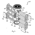
- Fig.1 shows a stirrer 01, which can be used in a kettle for the preparation of food and the mixing and heating or cooling of the food is used.
- the stirrer 01 is produced as a welded part and essentially consists of a stirrer head 02, eight stirring vanes 03 and the stirring vanes 03 or the stirrer head 02 connecting webs 04, 05, 06, 07 and 08 constructed.
- the impellers 03 and the webs 04 to 08 are double-walled and connected to form a closed conduit, so that a cooling or heating medium flowing in at the stirrer head 02 can flow through the stirrer 01 along this conduit and thereby dissipate heat energy or couple thermal energy into it.
- the agitator blades 03 are inclined with respect to their horizontally extending plane of movement at an angle of approximately 20 °, so that the rotational movement of the agitator 01 about its central axis, the mass flowing past the agitator blades 03 is deflected upwards or downwards, so that the mass is permanently mixed and do not form any standing zones.
- a drive shaft not shown, provided in the mixing vessel, which extends from the bottom of the mixing vessel up and can be brought into a receptacle on the agitator 02 in engagement.
- the drive shaft does not collide with the agitator 01, the web 07 is formed in the manner of a loop, so that the drive shaft can pass through the agitator 01 in the region of the web 07.
- each stripping elements 09 are fixed, which in the rotational drive movement of the agitator 01 along the component wall of the Rrindgefäßes be performed so that form no standing zones in the boundary region between the mass and the component, but also in this area optimum mixing is achieved.
- the stripping elements 09 can be adjustably mounted on the agitator 01, so that a size compensation is made possible.
- the Fig. 2 and 3 show the agitator 01 in two different perspective views.
- agitator head 02 is shown enlarged as a grid model.
- the lid of the stirrer head 02 with the connections for inlet and outlet of the cooling or heating medium is not shown in this grid model.
- the agitator head has two concentrically arranged chambers 10 and 11, which are separated by a partition wall 12 from each other.
- the webs 04 both open into the inner chamber 11, whereas the webs 08 open into the outer chamber 10. This ensures that the fresh cooling or heating medium via the outer chamber 10 and the webs 08 can flow into the agitator 01 and back through the partition 12 of the already heated or cooled cooling or heating medium, the back over the webs 04 flows back into the chamber 11 of the agitator head 02, is separated.
- the schematic structure and the function of the stirrer head 02 are based on the in Fig. 5 illustrated schematic cross section recognizable.
- the two chambers 10 and 11 are separated from the partition wall 12 from each other. Both chambers 10 and 11 are bounded by a fixedly arranged cover 13 and a rotatably mounted together with the agitator trough 14 to the outside.
- the partition wall 12 is liquid-tightly welded to the bottom of the tub 14.
- the cooling or heating medium flows into the chamber 10 and from there into the webs 08, which form the inlet into the conduit through the agitator 01.
- shaft sealing rings 17 are arranged in the sealing gaps between the stationary cover 13 and the trough 14 rotating together with the stirring vanes.
- a compressed air connection 18 is also provided in the cover 13, to which a compressed air line can be connected. Compressed air can be pressed into the chamber 10 via the compressed air connection 18, so that the cooling or heating medium located in the stirrer 01 can be displaced outwards via the chamber 11 and the outlet 16.
- the center of the trough 14 is formed as a polygonal toothing 19, in which the complementary shape formed end of a drive shaft 20 is engageable, so that a torque from the drive shaft 20 can be transmitted to the trough 14.
- a broken represented Eingreifologyelement 21 is attached to prevent external intervention in the driven agitator 01.
- Fig. 6 shows the agitator 01, as it can be arranged in a stirred vessel 22 designed as a cooking vessel.
- Fig. 7 represents the agitator 01 and the mixing vessel 22 in top view.
- the mixing vessel 22 in turn is also double-walled. and can be flowed through by the same cooling or heating medium as the agitator 01, so that the arranged in the mixing vessel 22 food can be heated or cooled in a shorter time.
- Fig. 8 shows a second embodiment of an agitator according to the invention in a side view.
- the double-walled webs 03, 04, 05, 06, 07 and 08 are provided, which can be traversed by a suitable coolant, such as ice-cream.
- the ends of the webs 04 and 08 respectively open into the agitator head 23, which is formed from a cover 24 and a trough 25.
- a receptacle In order to transmit the drive power of the drive motor to the agitator 26, a receptacle is provided, which consists of two vertical webs 34 and 35 and three attached thereto réellevielkantiatan 31, 32 and 33 (see Fig. 9 ) is formed.
- a receptacle In the Fig. 8 not shown, in the mixing vessel vertically upwardly extending drive shaft is in the inner polyhedron elements 31 to 33 form-fitting engagement to transmit the drive torque to the agitator 26. It is a particular advantage in this case that the agitator 26 can be plugged from above onto the drive shaft in a simple manner, without a disassembly of the agitator head 23 being necessary in particular.
- agitator 26 is shown in a perspective view, wherein in particular the agitator blades 09 are recognizable.
- Fig. 10 represents the structure of the agitator head 23 in cross section.
- the agitator head 23 is essentially formed from an annular trough 25 and a cover 24 rotatably mounted thereon.
- a fastening ring 29 and a bearing element 30 designed in the manner of a roller bearing are provided.
- the fastening ring 29 is rotatably mounted on the inner ring 27 of the trough 25 by means of the bearing element 30.
- To attach the lid 24 to the tub 25 mounting screws are inserted through corresponding recesses in the cover 24 and screwed from above into the mounting ring 29, which in Fig. 10 indicated by dash-dotted lines.
- the lid 24 is thereby rotatably mounted on the trough 25, so that only the attachment of the inlet 15 and the drain 16 is necessary for mounting or dismounting of the agitator 23 in a mixing vessel.
- the inlet chamber 10 is formed in the center of the trough 25, which is bounded laterally by the inner ring 27.
- the outlet chamber 11 is bounded by the component wall of the trough 25 and the fastening ring 29. Due to the different sealing rings 17, the two chambers 10 and 11 are sealed liquid-tight, so that during operation of the agitator 26, the coolant can not escape from the chambers 10 and 11 through the sealing gaps.
- a very compact agitator be designed, which ensures that the pressure acting on the various components of the agitator head 23 compressive forces even at high internal pressures, as they occur in particular when using Eisbrei as a coolant , do not exceed a tolerable level.
Landscapes
- Engineering & Computer Science (AREA)
- Life Sciences & Earth Sciences (AREA)
- Chemical & Material Sciences (AREA)
- Food Science & Technology (AREA)
- Polymers & Plastics (AREA)
- Wood Science & Technology (AREA)
- Zoology (AREA)
- Chemical Kinetics & Catalysis (AREA)
- General Engineering & Computer Science (AREA)
- Manufacturing & Machinery (AREA)
- Health & Medical Sciences (AREA)
- Nutrition Science (AREA)
- Mechanical Engineering (AREA)
- Thermal Sciences (AREA)
- Physics & Mathematics (AREA)
- Mixers Of The Rotary Stirring Type (AREA)
- Food-Manufacturing Devices (AREA)
- Table Equipment (AREA)
- Table Devices Or Equipment (AREA)
- Freezing, Cooling And Drying Of Foods (AREA)
- Commercial Cooking Devices (AREA)
- Accessories For Mixers (AREA)
- Thermotherapy And Cooling Therapy Devices (AREA)
- Meat, Egg Or Seafood Products (AREA)
- General Preparation And Processing Of Foods (AREA)
- Compression-Type Refrigeration Machines With Reversible Cycles (AREA)
- Food Preservation Except Freezing, Refrigeration, And Drying (AREA)
- Manufacturing And Processing Devices For Dough (AREA)
- Confectionery (AREA)
- Beans For Foods Or Fodder (AREA)
Description
- Die Erfindung betrifft ein Verfahren zur Herstellung von vorgekochten Speisen nach dem Oberbegriff des Anspruchs 1.
- In vielen Gemeinschaftsverpflegungseinrichtungen, beispielsweise Kantinen von Großbetrieben oder in Krankenhäusern, ist es erforderlich, dass an sieben Tagen der Woche Speisen ausgegeben werden. Werden diese Speisen an sieben Tagen der Woche jeweils frisch zubereitet, entstehen dadurch hohe Kosten, da der Einsatz des Küchenpersonals über das Wochenende nur bei Zahlung von entsprechenden Aufschlägen möglich ist. Es wird deshalb vielfach ein Verfahren eingesetzt, das in Fachkreisen als "Cook and Chill" bezeichnet wird. Bei diesem Verfahren werden die Speisen nur wochentags zubereitet, wobei die für das Wochenende erforderlichen Portionen in dieser Zeit vorgekocht werden. Nach der Zubereitung der vorgekochten Speisemenge wird diese auf eine Temperatur unterhalb von 8°C heruntergekühlt und bei einer geeigneten Kühltemperatur gelagert. Dabei sollte eine Temperatur von 3°C zumindest einmal kurz unterschritten werden. Die Speisemasse kann dann zum Verzehr an den Wochenenden im Ganzen oder portionsweise aufgewärmt werden.
- Problematisch an dem "Cook and Chill"-Verfahren ist es, dass es aufgrund der Lagerung der Speisen bis zu deren Aufwärmung zu hygienischen Belastungen kommen kann. Dabei ist weniger die Lagerung bei einer Temperatur unterhalb von 8°C kritisch, da sich bei diesen Temperaturen Mikroorganismen wie Bakterien und Pilze kaum vermehren. Als kritische Größe ist vielmehr die Abkühlphase anzusehen, während der die Speisen einen Temperaturbereich von 55°C bis zur Endtemperatur unter 8°C durchlaufen. In diesem Temperaturband finden Mikroorganismen in der vorgekochten Speise optimale Vermehrungsbedingungen und können sich somit während der Abkühlphase besonders stark vermehren.
- Um die Vermehrung der Mikroorganismen während der Abkühlphase unterhalb eines tolerierbaren Maßes zu halten, ist es erforderlich, dass die vorgekochten Speisen innerhalb möglichst kurzer Zeit auf die Endtemperatur heruntergekühlt werden. Um die Vermehrung der Mikroorganismen während der Abkühlphase zuverlässig reduzieren zu können, ist es zwingend, dass nicht nur Teilbereiche der Speise die Endtemperatur innerhalb ausreichend kurzer Zeit erreicht haben, sondern dass die Speisemasse ausgehend vom Rand bis hin zum Kern durchgehend auf die Endtemperatur abgekühlt ist.
- Wird die Speise, beispielsweise durch Einbringung eines die Speisemasse enthaltenden Behälters in einen Kühlschrank, lediglich vom Rand ausgehend gekühlt, so hängt die Dauer, bis der Kern der Speisenmasse die Endtemperatur erreicht hat, vom Volumen der Speisemasse relativ zu seiner Randfläche, an der gekühlt werden kann, ab. Um die Abkühlphase beim Durchfahren des kritischen Temperaturbereichs bis zur Erreichung der Endtemperatur auch im Kern der Speisemasse auf ein tolerierbares Maß im Bereich unterhalb von 120 Minuten, insbesondere kürzer als 90 Minuten, zu halten, ist es deshalb bekannt, die Speise vorportioniert in flache Behälter abzufüllen und erst diese flachen Behälter dann einzeln herunterzukühlen. Durch das Vorportionieren in kleinere Behälter werden allerdings wiederum höhere Kosten verursacht.
- Die
DE 40 09 157 C2 beschreibt ein Verfahren zur Vorbehandlung von Reis, bei dem der Reis entsprechend einem bestimmten Temperaturprozess vorgekocht und anschließend getrocknet wird. - Die
EP 0 338 282 B1 offenbart ein Verfahren zur sterilen Vorkochung von Nudelprodukten, die nach der Kochung verzehrfertig abgepackt werden können. - Die
DE 37 27 594 A1 , dieDE-OS 1 926 704 und dieDE 32 00 165 A1 beschreiben jeweils Rührwerke, bei denen das Rührwerk in der Art eines Wärmetauschers ausgebildet ist und von einem Kühl- bzw. Heizmedium durchströmt werden kann. - Die
US-A-5 218 898 offenbart ein Verfahren gemäß dem Oberbegriff des Anspruchs 1. Aufgabe der vorliegenden Erfindung ist es ein neues Verfahren zur Kühlung einer Vielzahl von Portionen einer vorgekochten Speise gemäß Anspruch 1 vorzuschlagen, ohne diese vor dem Kühlprozess vorportionieren zu müssen. - Vorteilhafte Ausführungsformen der Erfindung sind Gegenstand der Unteransprüche.
- Ein Vorteil des erfindungsgemäßen Verfahrens liegt insbesondere darin, dass die Speise während der Abkühlphase zugleich gekühlt und durch Einsatz eines Rührwerks durchmischt wird. Durch die Durchmischung der Speisemasse, die später eine Vielzahl von einzelnen Speiseportionen ergibt, kann ein rascher Temperaturausgleich zwischen den einzelnen Temperaturbereichen im Rührkessel bewirkt werden. Außerdem wird durch den Einsatz eines als Wärmetauschers ausgebildeten Rührwerks, das von einem gasförmigen oder flüssigen Kühlmittel durchströmt wird, die mit der Speise in Kontakt befindliche Kühlfläche erheblich vergrößert. Im Ergebnis kann durch diese beiden Maßnahmen die Abkühlphase zum Durchfahren des kritischen Temperaturbereiches zwischen 55°C und 8°C erheblich verkürzt werden.
- Grundsätzlich ist es möglich, die Speise lediglich durch Einsatz des als Wärmetauscher ausgebildeten Rührwerks zu kühlen. Die Kühlleistung lässt sich aber noch erheblich erhöhen, wenn während der Abkühlphase auch der Rührkessel gekühlt wird. Dazu können konventionelle Rührkessel verwendet werden, die doppelwandig ausgebildet sind und von einem Kühlmittel, beispielsweise Eiswasser, Eisbrei oder einer Gykol-Wasser-Mischung, durchströmbar sind.
- Zur Durchführung des erfindungsgemäßen Verfahrens ist ein neuartiges Rührwerk erforderlich, das in Zusammenwirken mit dem Rührgefäß zur Durchmischung der Speisen geeignet ist. Gattungsgemäß ist das Rührwerk in der Art eines Wärmetauschers ausgebildet und kann von einem Kühlmedium durchströmt werden, so dass im Ergebnis Wärmeenergie aus der Speisemasse abgeführt werden kann. Um einen ausreichenden Strömungsquerschnitt im Rührwerkkopf realisieren zu können, wie er insbesondere bei der Verwendung von Eisbrei als Kühlmittel notwendig ist, ist beim Rührwerk der Rührwerkkopf aus einem feststehend angeordneten Deckel und einer zusammen mit dem Rührwerk drehbaren Wanne gebildet, wobei der Deckel dichtend auf der Wanne befestigbar ist.
- Wird das Rührwerk statt von einem Kühlmedium von einem Heizmedium, beispielsweise Heißwasser oder Heißdampf, durchströmt, ist es selbstverständlich auch möglich, die vom Rührwerk durchmischte Speisemasse zu erwärmen. Dadurch kann die Dauer der Aufwärmphase während der Zubereitung der Speisen erheblich verkürzt werden, da größere Wärmemengen in kürzerer Zeit in die Speisemasse einkoppelbar sind.
- Durchmischbare Massen im Sinne dieser Erfindung sind alle Stoffe bzw. Stoffgemische, deren Aggregatszustand zumindest noch eine geringfügige Durchmischung erlaubt. Darunter fallen insbesondere auch hochviskose Massen, wie beispielsweise ein Kartoffelbrei, oder Gemische aus flüssigen Bestandteilen und Feststoffbestandteilen, wie beispielsweise ein Eintopf.
- Beim Einsatz des Rührwerks bei der Zubereitung von Speisen richten sich dessen Abmessungen im Wesentlichen nach den Abmessungen bzw. der maximalen Füllmenge der Kessel, in denen die Speisen aufgenommen werden. Je nach erforderlicher Kühl- bzw. Heizleistung kann die vom Rührwerk dargestellte Kühl- bzw. Heizfläche in einfacher Weise dadurch angepasst werden, dass beispielsweise die Anzahl der Rührflügel erhöht wird. Die Außenabmessungen des Rührwerks können dabei unverändert bleiben.
- Als Kühl- und/oder Heizmedium können alle gasförmigen oder flüssigen Medien, beispielsweise Eiswasser, eine Glykol-Wasser-Mischung, flüssiger Stickstoff, Heißwasser oder Heißdampf, zum Einsatz kommen, da das Kühl- bzw. Heizmedium lediglich die Wärmeenergie aus der zu durchmischenden Masse abführt beziehungsweise in diese einkoppelt, aber kein direkter Stoffaustausch stattfindet. Im Lebensmittelbereich sind besonders Eiswasser, Heißwasser und Heißdampf zum Einsatz im erfindungsgemäßen Rührwerk geeignet, da diese Medien in Großküchen vielfach bereits vorhanden sind und außerdem auch im Falle von Störungen, das heißt falls das Medium aus dem Rührwerk uneewünscht austritt, beispielsweise durch Leckagen, keine Gesundheitsgefährdung darstellen.
- Die konstruktive Ausführung des Rührwerks ist grundsätzlich beliebig, solange an den Außenflächen des Rührwerks, die mit der zu durchmischenden Masse in Kontakt kommen, ein ausreichender Wärmeaustausch zwischen der Masse und dem das Rührwerk durchströmenden Kühl- bzw. Heizmedium ermöglicht wird. Besonders vorteilhaft ist es, wenn das Rührwerk einen Rührwerkkopf und einen beziehungsweise mehrere Rührflügel aufweist, wobei der Rührwerkkopf und die verschiedenen Rührwerksflügel durch Stege miteinander verbunden sind. Die Rührflügel und Stege sind dabei doppelwandig auszuführen und stellen dadurch einzelne Leitungsabschnitte dar. Durch entsprechend dichtende Verbindung zwischen den Rührflügeln, den Stegen und dem Rührwerkkopf, beispielsweise durch Verschweißen der einzelnen Teile, entsteht dann eine geschlossene Leitung, deren Einlauf und Rücklauf in den Rührwerkkopf mündet. An dem Rührwerkkopf seinerseits ist ein Zu- und ein Ablauf für das Kühl- bzw. Heizmedium vorgesehen. Im Ergebnis strömt also das Kühl- bzw. Heizmedium in den Rührwerkkopf ein und durchströmt von dort ausgehend die einzelnen Rührflügel und die die Rührflügel verbindenden Stege. Das aufgrund des Wärmeaustausches in den Stegen beziehungsweise Rührflügeln abgekühlte beziehungsweise erwärmte Medium strömt dann wiederum über den Rührwerkkopf aus und wird über den Ablauf abgeführt. Dabei ist es besonders vorteilhaft, wenn das Kühl- bzw. Heizmedium in einem Kühl- bzw. Heizkreislauf durch einen Kühler bzw. eine Heizeinrichtung geführt wird. Selbstverständlich ist es auch möglich, dass ausgehend vom Rührwerkkopf mehrere parallel zueinander verlaufende Leitungen durch die einzelnen Rührflügel und Stege verlaufen, so dass das Rührwerk entlang mehrerer parallel zueinander verlaufender Leitungen vom Kühl- bzw. Heizmedium durchströmbar ist.
- Um die Durchmischung des Kühl- bzw. Heizmediums am Ein- bzw. Rücklauf im Rührwerkkopf zu verhindern, kann der Rührwerkkopf zwei getrennte Kammern aufweisen. Die erste Kammer bildet dabei den Einlauf der Leitung durch das Rührwerk und kann an den Zulauf für das Kühl- bzw. Heizmedium angeschlossen werden. Die zweite Kammer bildet dann den Rücklauf der Leitung durch das Rührwerk und ist an den Ablauf für das Kühl- bzw. Heizmedium anschließbar. Durch die Trennwandung zwischen den beiden Kammern wird eine Durchmischung des frischen Kühl- bzw. Heizmediums am Einlauf mit dem bereits erwärmten bzw. abgekühlten Kühl- bzw. Heizmedium am Rücklauf ausgeschlossen.
- Um die Anschlüsse für den Zu- und Ablauf des Kühl- bzw. Heizmediums einfach ausbilden zu können, beispielsweise in der Art von Steckkupplungen, an denen geeignete Schläuche anschließbar sind, ist es vorteilhaft, wenn der Rührwerkkopf einen feststehenden und einen zusammen mit den Rührflügeln drehbaren Teil aufweist. In den feststehenden Teil werden dann die Anschlüsse für den Zu- bzw. Ablauf des Kühl- bzw. Heizmediums angeordnet, wohingegen der drehbar gelagerte Teil des Rührwerkkopfs den Ein- bzw. Auslauf in die Leitung durch das Rührwerk darstellt.
- Um den Rührflügel in unterschiedlichen Rührkesseln einsetzen zu können, ist es vorteilhaft, wenn am Rührwerkkopf wahlweise unterschiedliche Adapterelemente befestigt werden können, die jeweils mit verschiedenen Antriebswellen in Eingriff bringbar sind. Im Ergebnis kann dadurch erreicht werden, dass das Rührwerk mit dem Rührwerkkopf, den Rührflügeln und Stegen in einheitlichen Baureihen hergestellt werden kann und eine Anpassung an unterschiedliche Antriebswellen durch Anbringung verschiedener Adapterelemente ermöglicht wird.
- Alternativ zum Antrieb des Rührwerks mittels eines Antriebsmotors und eine die Drehbewegung übertragenden Antriebswelle kann auch die Strömungsenergie des am Einlauf einströmenden Kühl- bzw. Heizmediums zum Antrieb des Rührwerks ausgenutzt werden. Beispielsweise können dazu bekannte Strömungslamellen im Rührwerkkopf angeordnet werden, die die Strömungsenergie des einströmenden Mediums in eine Drehbewegung umwandeln.
- Bevorzugte Ausführungsformen sind in den Zeichnungen beispielhaft dargestellt und werden nachfolgend näher erläutert.
- Es zeigen:
- Fig.1
- ein Rührwerk in seitlicher Ansicht;
- Fig.2
- das Rührwerk gemäß
Fig. 1 in einer ersten perspektivischen Ansicht; - Fig.3
- das Rührwerk gemäß
Fig. 1 in einer zweiten perspektivischen Ansicht; - Fig.4
- das Gitternetzmodell eines Rührwerkkopfes;
- Fig.4
- einen Rührwerkkopf in einem schematisch dargestellten Querschnitt;
- Fig.6
- ein Rührgefäß mit Rührwerk in perspektivischer Ansicht;
- Fig.7
- das Rührgefäß mit Rührwerk gemäß
Fig. 6 in Ansicht von oben; - Fig.8
- eine zweite Ausführungsform eines Rührwerks in seitlicher Ansicht;
- Fig.9
- das Rührwerk gemäß
Fig. 8 in einer ersten perspektivischen Ansicht; - Fig. 10
- den Rührwerkkopf des Rührwerks gemäß
Fig. 8 im Querschnitt; -
Fig.1 zeigt ein Rührwerk 01, das in einem Kessel zur Zubereitung von Speisen Verwendung finden kann und der Durchmischung und Aufheizung bzw. Kühlung der Speisen dient. - Das Rührwerk 01 ist als Schweißteil hergestellt und im Wesentlichen aus einem Rührwerkkopf 02, acht Rührflügeln 03 und die Rührflügel 03 beziehungsweise den Rührwerkkopf 02 verbindenden Stegen 04, 05, 06, 07 und 08 aufgebaut. Die Rührflügel 03 und die Stege 04 bis 08 sind doppelwandig ausgebildet und zu einer geschlossenen Leitung verbunden, so dass ein am Rührwerkkopf 02 einströmendes Kühl- bzw. Heizmedium das Rührwerk 01 entlang dieser Leitung durchströmen und dabei Wärmeenergie abführen bzw. Wärmeenergie einkoppeln kann.
- Die Rührflügel 03 sind gegenüber ihrer horizontal verlaufenden Bewegungsebene mit einem Winkel von circa 20° geneigt, so dass beim rotatorischen Antrieb des Rührwerks 01 um seine Mittelachse die an den Rührflügeln 03 vorbeiströmende Masse nach oben beziehungsweise unten abgelenkt wird, so dass die Masse permanent durchmischt wird und sich keine stehenden Zonen bilden.
- Zum Antrieb des Rührwerks 01 dient eine nicht dargestellte, im Rührgefäß vorgesehene Antriebswelle, die sich vom Boden des Rührgefäßes nach oben erstreckt und in einer Aufnahme am Rührwerkkopf 02 in Eingriff gebracht werden kann. Damit die Antriebswelle nicht mit dem Rührwerk 01 kollidiert, ist der Steg 07 in der Art einer Ringleitung ausgebildet, so dass die Antriebswelle das Rührwerk 01 im Bereich des Stegs 07 durchgreifen kann.
- An zwei der Stege 05 und an den beiden unteren Rührflügeln 03 sind jeweils Abstreifelemente 09 befestigt, die bei der rotatorischen Antriebsbewegung des Rührwerks 01 entlang der Bauteilwandung des Rührgefäßes geführt werden, so dass sich im Grenzbereich zwischen Masse und Bauteilwandung keine stehenden Zonen bilden, sondern auch in diesem Bereich eine optimale Durchmischung erreicht wird. Um das Rührwerk in Rührgefäßen unterschiedlicher Abmessungen einsetzen zu können, können die Abstreifelemente 09 verstellbar am Rührwerk 01 befestigt sein, so dass ein Größenausgleich ermöglicht wird.
- Die
Fig. 2 und3 zeigen das Rührwerk 01 in zwei unterschiedlichen perspektivischen Ansichten. - In
Fig. 4 ist der Rührwerkkopf 02 als Gitternetzmodell vergrößert dargestellt. Der Deckel des Rührwerkkopfs 02 mit den Anschlüssen für Zu- und Ablauf des Kühl- bzw. Heizmediums ist in diesem Gitternetzmodell nicht dargestellt. Der Rührwerkkopf weist zwei konzentrisch angeordnete Kammern 10 und 11 auf, die durch eine Trennwandung 12 voneinander getrennt sind. Die Stege 04 münden beide in die innere Kammer 11, wohingegen die Stege 08 in die äußere Kammer 10 münden. Dadurch wird erreicht, dass das frische Kühl- bzw. Heizmedium über die äußere Kammer 10 und die Stege 08 in das Rührwerk 01 einströmen kann und durch die Trennwandung 12 von dem bereits erwärmten beziehungsweise abgekühlten Kühl- bzw. Heizmedium, das über die Stege 04 zurück in die Kammer 11 des Rührwerkkopfs 02 zurückströmt, getrennt ist. - Der schematische Aufbau und die Funktion des Rührwerkkopfes 02 sind anhand des in
Fig. 5 dargestellten schematischen Querschnitts erkennbar. Die beiden Kammern 10 und 11 werden von der Trennwandung 12 voneinander getrennt. Beide Kammern 10 und 11 werden von einem feststehend angeordneten Deckel 13 und einer zusammen mit dem Rührwerk drehbar gelagerten Wanne 14 nach außen hin begrenzt. Die Trennwandung 12 ist flüssigkeitsdicht am Boden der Wanne 14 festgeschweißt. - Über den Zulauf 15 strömt das Kühl- bzw. Heizmedium in die Kammer 10 ein und gelangt von dort in die Stege 08, die den Einlauf in die Leitung durch das Rührwerk 01 bilden. Hat das Kühl- bzw. Heizmedium alle Stege 04 bis 08 und die Rührflügel 03 durchflossen, strömt es über die den Rücklauf bildenden Stege 04 in die Kammer 11 des Rührwerkkopfes 02 zurück, von wo es über den Ablauf 16 abgeführt werden kann. Zur Abdichtung der Kammern 10 und 11 sind in den Dichtspalten zwischen dem feststehenden Deckel 13 und der sich zusammen mit den Rührflügeln drehenden Wanne 14 bzw. der Trennwandung 12 Wellendichtringe 17 angeordnet.
- Neben dem Zulauf 15 und dem Ablauf 16 ist in dem Deckel 13 außerdem noch ein Druckluftanschluss 18 vorgesehen, an dem eine Druckluftleitung anschließbar ist. Über dem Druckluftanschluss 18 kann Druckluft in die Kammer 10 eingepresst werden, so dass das im Rührwerk 01 befindliche Kühl- bzw. Heizmedium über die Kammer 11 und den Ablauf 16 nach außen verdrängt werden kann.
- Die Mitte der Wanne 14 ist als Vielkantverzahnung 19 ausgebildet, in der das formkomplementär ausgebildete Ende einer Antriebswelle 20 in Eingriff bringbar ist, so dass ein Drehmoment von der Antriebswelle 20 auf die Wanne 14 übertragen werden kann. Am Deckel 13 ist ein gebrochen dargestelltes Eingreifschutzelement 21 befestigt, um ein Eingreifen von außen in das angetriebene Rührwerk 01 zu verhindern.
-
Fig. 6 zeigt das Rührwerk 01, wie es in einem als Kochkessel ausgebildeten Rührgefäß 22 angeordnet werden kann. -
Fig. 7 stellt das Rührwerk 01 und das Rührgefäß 22 in Ansicht von oben dar. Das Rührgefäß 22 seinerseits ist ebenfalls doppelwandig ausgebildet. und kann vom gleichen Kühl- bzw. Heizmedium durchströmt werden wie das Rührwerk 01, so dass die im Rührgefäß 22 angeordneten Speisen in kürzerer Zeit aufgeheizt beziehungsweise abgekühlt werden können. -
Fig. 8 stellt eine zweite Ausführungsform eines erfindungsgemäßen Rührwerks in seitlicher Ansicht dar. Wie beim Rührwerk 01 sind die doppelwandig ausgebildeten Stege 03, 04, 05, 06, 07 und 08 vorgesehen, die von einem geeigneten Kühlmittel, beispielsweise Eisbrei, durchströmt werden können. Die Enden der Stege 04 und 08 münden jeweils in den Rührwerkkopf 23, der aus einem Deckel 24 und einer Wanne 25 gebildet ist. - Um die Antriebsleistung des Antriebsmotors auf das Rührwerk 26 übertragen zu können, ist eine Aufnahme vorgesehen, die aus zwei Vertikalstegen 34 und 35 und drei daran befestigten Innenvielkantelementen 31, 32 und 33 (siehe
Fig. 9 ) gebildet ist. Die inFig. 8 nicht dargestellte, sich im Rührgefäß vertikal nach oben erstreckende Antriebswelle kommt in den Innenvielkantelementen 31 bis 33 formschlüssig zum Eingriff, um das Antriebsmoment auf das Rührwerk 26 zu übertragen. Einen besonderen Vorteil stellt es dabei dar, dass das Rührwerk 26 in einfacher Weise von oben auf die Antriebswelle aufgesteckt werden kann, ohne dass insbesondere eine Demontage des Rührwerkkopfes 23 notwendig ist. - In
Fig. 9 ist das Rührwerk 26 in perspektivischer Ansicht dargestellt, wobei insbesondere die Rührflügel 09 erkennbar sind. -
Fig. 10 stellt den Aufbau des Rührwerkkopfes 23 im Querschnitt dar. Der Rührwerkkopf 23 wird im Wesentlichen aus einer kreisringförmigen Wanne 25 und einem daran drehbar gelagerten Deckel 24 gebildet. Zur Realisierung der drehbaren Lagerung des Deckels 24 an der Wanne 25 sind ein Befestigungsring 29 und ein in der Art eines Wälzlagers ausgebildetes Lagerelement 30 vorgesehen. Der Befestigungsring 29 ist am Innenring 27 der Wanne 25 mittels des Lagerelements 30 drehbar gelagert. Zur Befestigung des Deckels 24 an der Wanne 25 werden Befestigungsschrauben durch entsprechende Ausnehmungen im Deckel 24 durchgesteckt und von oben in den Befestigungsring 29 eingeschraubt, was inFig. 10 durch strichpunktierte Linien angedeutet ist. Im Ergebnis ist dadurch der Deckel 24 drehbar an der Wanne 25 gelagert, so dass zur Montage bzw. Demontage des Rührwerks 23 in einem Rührgefäß nur die Befestigung des Zulaufs 15 und des Ablaufs 16 notwendig ist. - Durch die kreisringförmige Ausbildung der Wanne 25 wird im Zentrum der Wanne 25 die Einlaufkammer 10 gebildet, die seitlich vom Innenring 27 begrenzt wird. Die Auslaufkammer 11 wird von der Bauteilwandung der Wanne 25 und dem Befestigungsring 29 begrenzt. Durch die verschiedenen Dichtringe 17 werden die beiden Kammern 10 und 11 flüssigkeitsdicht abgedichtet, so dass im Betrieb des Rührwerks 26 das Kühlmittel nicht aus den Kammern 10 und 11 durch die Dichtspalte hindurch austreten kann. Durch die Anordnung der Kammer 10 im Zentrum der Wanne 25 kann ein sehr kompakter Rührwerkkopf gestaltet werden, wodurch erreicht wird, dass die auf die verschiedenen Bauteile des Rührwerkkopfes 23 wirkenden Druckkräfte auch bei hohen Innendrücken, wie sie insbesondere bei der Verwendung von Eisbrei als Kühlmittel auftreten, ein tolerierbares Maß nicht überschreiten.
Claims (4)
- Verfahren zur Herstellung einer Vielzahl von Portionen einer vorgekochten Speise,- bei dem die Speise zunächst bei Temperaturen von über 55°C gekocht und verzehrfertig zubereitet wird,- anschließend die Speise in einer Abkühlphase von der Zubereitungstemperatur auf eine Endtemperatur abgekühlt wird, wobei die Speise während der Abkühlphase von einem als Wärmetauscher ausgebildeten Rührwerk (01) gleichzeitig durchmischt und abgekühlt wird,
dadurch gekennzeichnet,
dass die Speise in der Abkühlphase im gleichen, auch zur Erhitzung der Speisen geeigneten Rührkessel (22) verbleibt, und zumindest so schnell abgekühlt wird, dass der Temperaturbereich von 55°C bis 8°C innerhalb einer Zeit von maximal 120 min durchfahren wird,- die Speise bei einer Endtemperatur im Bereich von 8°C bis 0°C für einige Tage gelagert wird,- anschließend die Speise auf eine zum Verzehr geeignete Temperatur aufgewärmt wird. - Verfahren nach Anspruch 1,
dadurch gekennzeichnet,
dass die Abkühlphase maximal ca. 90 min dauert. - Verfahren nach Anspruch 1 oder 2,
dadurch gekennzeichnet,
dass die Endtemperatur ca. 3°C beträgt. - Verfahren nach einem der Ansprüche 1 bis 3,
dadurch gekennzeichnet,
dass auch der Rührkessel (22) in der Abkühlphase gekühlt wird.
Priority Applications (1)
| Application Number | Priority Date | Filing Date | Title |
|---|---|---|---|
| SI200230702T SI1475001T1 (sl) | 2001-02-08 | 2002-02-04 | Postopek priprave mnoĹľice porcij predhodno kuhane jedi |
Applications Claiming Priority (3)
| Application Number | Priority Date | Filing Date | Title |
|---|---|---|---|
| DE10106087 | 2001-02-08 | ||
| DE10106087A DE10106087C2 (de) | 2001-02-08 | 2001-02-08 | Verfahren zur Herstellung vorgekochter Speisen und Rührwerk |
| EP02704626A EP1357806B1 (de) | 2001-02-08 | 2002-02-04 | Als wärmetauscher ausgebildetes rührwerk |
Related Parent Applications (1)
| Application Number | Title | Priority Date | Filing Date |
|---|---|---|---|
| EP02704626A Division EP1357806B1 (de) | 2001-02-08 | 2002-02-04 | Als wärmetauscher ausgebildetes rührwerk |
Publications (3)
| Publication Number | Publication Date |
|---|---|
| EP1475001A2 EP1475001A2 (de) | 2004-11-10 |
| EP1475001A3 EP1475001A3 (de) | 2006-04-12 |
| EP1475001B1 true EP1475001B1 (de) | 2008-04-23 |
Family
ID=7673516
Family Applications (2)
| Application Number | Title | Priority Date | Filing Date |
|---|---|---|---|
| EP04013214A Expired - Lifetime EP1475001B1 (de) | 2001-02-08 | 2002-02-04 | Verfahren zur Herstellung einer Vielzahl von Portionen einer vorgekochten Speise |
| EP02704626A Expired - Lifetime EP1357806B1 (de) | 2001-02-08 | 2002-02-04 | Als wärmetauscher ausgebildetes rührwerk |
Family Applications After (1)
| Application Number | Title | Priority Date | Filing Date |
|---|---|---|---|
| EP02704626A Expired - Lifetime EP1357806B1 (de) | 2001-02-08 | 2002-02-04 | Als wärmetauscher ausgebildetes rührwerk |
Country Status (11)
| Country | Link |
|---|---|
| US (1) | US6938435B2 (de) |
| EP (2) | EP1475001B1 (de) |
| JP (1) | JP2004521624A (de) |
| AT (2) | ATE392948T1 (de) |
| AU (1) | AU2002238398A1 (de) |
| DE (3) | DE10106087C2 (de) |
| DK (2) | DK1475001T3 (de) |
| ES (2) | ES2305616T3 (de) |
| PT (1) | PT1475001E (de) |
| SI (1) | SI1475001T1 (de) |
| WO (1) | WO2002062158A2 (de) |
Families Citing this family (15)
| Publication number | Priority date | Publication date | Assignee | Title |
|---|---|---|---|---|
| JP3935033B2 (ja) * | 2002-09-06 | 2007-06-20 | 住友重機械工業株式会社 | 架台付の減速機のシリーズ |
| DE102004039317A1 (de) | 2004-08-12 | 2006-02-23 | Ewald Nied | Vorrichtung zum Erwärmen und/oder Abkühlen einer durchmischbaren Masse |
| US8826560B2 (en) * | 2006-09-01 | 2014-09-09 | Kadant Inc. | Support apparatus for supporting a syphon |
| DE102007031335B4 (de) | 2007-07-05 | 2018-03-22 | Kälte-Eckert GmbH | Kocheinrichtung und Verfahren zum Kühlen einer Kocheinrichtung |
| DE102007049016B3 (de) | 2007-10-11 | 2009-04-02 | Mkn Maschinenfabrik Kurt Neubauer Gmbh & Co. | Gargerät mit Rührwerk und Rückkühlmodul und Verfahren zum Betreiben eines derartigen Gargerätes |
| DE102008048811A1 (de) | 2007-11-09 | 2009-05-14 | Hubert Goseling | Kochkessel zur Zubereitung von Lebensmitteln |
| US8307849B2 (en) * | 2008-06-03 | 2012-11-13 | Jergens, Inc. | Rotary coupler and method of using same |
| US8903673B2 (en) * | 2011-03-11 | 2014-12-02 | Distek, Inc. | Centrally controlled modular motorized testing |
| US20120251385A1 (en) * | 2011-03-30 | 2012-10-04 | Chin-Chan Hsieh | Sterilization method of a food cooling device |
| CA2831343C (en) * | 2011-06-13 | 2019-04-16 | Fleury Michon | Method and system for preparation of fresh cooked meals |
| ITPR20120040A1 (it) * | 2012-06-20 | 2013-12-21 | Mauro Bianchini | Dispositivo per scaldare o raffreddare liquidi piu' o meno densi posti all'interno di un recipiente |
| BR112018014486B1 (pt) * | 2016-01-20 | 2022-05-10 | Praxair Technology, Inc | Método para fornecer uma quantidade desejada de resfriamento a uma quantidade de produto alimentício em um recipiente |
| FI126676B (fi) | 2016-04-01 | 2017-03-31 | Metos Oy Ab | Menetelmä suurtalouspadan jäähdyttämisen tehostamiseksi ja jäähdytettävä suurtalouspata |
| CN106417216B (zh) * | 2016-12-06 | 2022-03-22 | 山东省寄生虫病防治研究所 | 控温式诱蚊器 |
| CN113057356A (zh) * | 2021-03-18 | 2021-07-02 | 陈马莲 | 一种畜牧业用饲料高效杀菌搅拌装置 |
Family Cites Families (25)
| Publication number | Priority date | Publication date | Assignee | Title |
|---|---|---|---|---|
| US201704A (en) * | 1878-03-26 | Improvement in apparatus for obtaining glycerine from fats | ||
| US447566A (en) * | 1891-03-03 | Agitator for kettles or tanks | ||
| US1748320A (en) * | 1926-09-24 | 1930-02-25 | Creamery Package Mfg Co | Refrigerated agitating device |
| US1838610A (en) * | 1927-11-16 | 1931-12-29 | John A Bodes | Milk cooler |
| US2217379A (en) * | 1939-01-30 | 1940-10-08 | Peardon Gordon Joseph | Cooling device |
| US2254389A (en) * | 1939-04-15 | 1941-09-02 | Charles A Olcott | Means for preventing the dilution of sugar bearing materials |
| DE907060C (de) | 1949-12-09 | 1954-03-22 | Alfred Bauer | Praegemaschine zum Herstellen von Drucktypen fuer Bueromaschinen |
| DE1253214B (de) * | 1960-08-08 | 1967-11-02 | Weigelwerk G M B H | Braupfanne |
| DE1262974B (de) | 1962-08-16 | 1968-03-14 | Shionogi & Co | Kuehlmitteldurchflossener Ruehrer |
| DE1926704A1 (de) * | 1969-05-24 | 1970-11-26 | Harsanyi Dr Eugen | Ruehrwerk |
| US3739710A (en) * | 1971-12-30 | 1973-06-19 | Hubbert B & Son Inc | Processing kettle |
| US3903957A (en) * | 1972-01-19 | 1975-09-09 | Papenmeier Kg Maschf Guenther | Process for cooling granular materials being mixed |
| JPS5932536B2 (ja) | 1980-09-24 | 1984-08-09 | 日本鉱業株式会社 | 撹拌装置 |
| AT368442B (de) | 1981-01-26 | 1982-10-11 | Alber Franz | Anschlusstutzen |
| DE3200165A1 (de) * | 1982-01-07 | 1983-07-14 | Goavec S.A., 61006 Alençon, Orne | Ruehrwerk |
| DE3218637A1 (de) * | 1982-05-18 | 1983-11-24 | Haagen & Rinau | Mischvorrichtung |
| FR2560675B1 (fr) | 1984-03-05 | 1987-03-27 | Carboxyque Francaise | Procede et installation de refroidissement d'un produit visqueux notamment alimentaire |
| DE3727594A1 (de) * | 1987-08-19 | 1989-03-02 | Gortat Manfred | Maschine zum geregelten abkuehlen und aufheizen von sauerteigen |
| IT1217176B (it) * | 1988-04-18 | 1990-03-14 | Rossi E Catelli S P A | Procedimento per la produzione in continuo di pasta alimentare sterile,cotta o parzialmente cotta |
| DE4009157C2 (de) * | 1990-03-22 | 1999-05-06 | Buehler Gmbh | Verfahren und Vorrichtung zur hydro-thermischen Behandlung von Reis |
| DE9110133U1 (de) * | 1991-08-16 | 1991-09-26 | Rütgerswerke AG, 6000 Frankfurt | Rührwerksreaktor |
| US5218898A (en) | 1991-11-04 | 1993-06-15 | D C Norris & Company (Engineering) Limited | Food processing plant |
| US5381670A (en) | 1993-10-21 | 1995-01-17 | Tippmann; Joseph R. | Apparatus for cooling food by conduction |
| FI98653C (fi) * | 1995-08-29 | 1997-07-25 | Valmet Corp | Lauhteenpoistolaitteisto ja menetelmä lauhteen poiston säädössä |
| IT1295490B1 (it) * | 1997-10-01 | 1999-05-12 | Frigo Calor Snc Di Menegazzo G | Apparecchiatura a flussi contrapposti, particolarmente per abbattere rapidamente il calore nei cicli di conservazione dei cibi cotti e |
-
2001
- 2001-02-08 DE DE10106087A patent/DE10106087C2/de not_active Expired - Fee Related
-
2002
- 2002-02-04 DK DK04013214T patent/DK1475001T3/da active
- 2002-02-04 DE DE50202998T patent/DE50202998D1/de not_active Expired - Lifetime
- 2002-02-04 WO PCT/DE2002/000395 patent/WO2002062158A2/de not_active Ceased
- 2002-02-04 EP EP04013214A patent/EP1475001B1/de not_active Expired - Lifetime
- 2002-02-04 AT AT04013214T patent/ATE392948T1/de active
- 2002-02-04 PT PT04013214T patent/PT1475001E/pt unknown
- 2002-02-04 ES ES04013214T patent/ES2305616T3/es not_active Expired - Lifetime
- 2002-02-04 AT AT02704626T patent/ATE294507T1/de active
- 2002-02-04 JP JP2002562170A patent/JP2004521624A/ja active Pending
- 2002-02-04 ES ES02704626T patent/ES2240696T3/es not_active Expired - Lifetime
- 2002-02-04 DK DK02704626T patent/DK1357806T3/da active
- 2002-02-04 DE DE50212168T patent/DE50212168D1/de not_active Expired - Lifetime
- 2002-02-04 US US10/467,772 patent/US6938435B2/en not_active Expired - Fee Related
- 2002-02-04 SI SI200230702T patent/SI1475001T1/sl unknown
- 2002-02-04 AU AU2002238398A patent/AU2002238398A1/en not_active Abandoned
- 2002-02-04 EP EP02704626A patent/EP1357806B1/de not_active Expired - Lifetime
Also Published As
| Publication number | Publication date |
|---|---|
| DE50202998D1 (de) | 2005-06-09 |
| WO2002062158A2 (de) | 2002-08-15 |
| PT1475001E (pt) | 2008-06-24 |
| EP1475001A2 (de) | 2004-11-10 |
| ES2240696T3 (es) | 2005-10-16 |
| DK1357806T3 (da) | 2005-09-05 |
| EP1357806A2 (de) | 2003-11-05 |
| AU2002238398A1 (en) | 2002-08-19 |
| US6938435B2 (en) | 2005-09-06 |
| DE10106087C2 (de) | 2002-10-31 |
| ATE294507T1 (de) | 2005-05-15 |
| DE10106087A1 (de) | 2001-12-13 |
| US20040079091A1 (en) | 2004-04-29 |
| SI1475001T1 (sl) | 2008-10-31 |
| ES2305616T3 (es) | 2008-11-01 |
| DK1475001T3 (da) | 2008-09-01 |
| DE50212168D1 (de) | 2008-06-05 |
| JP2004521624A (ja) | 2004-07-22 |
| WO2002062158A3 (de) | 2002-12-19 |
| EP1357806B1 (de) | 2005-05-04 |
| EP1475001A3 (de) | 2006-04-12 |
| ATE392948T1 (de) | 2008-05-15 |
Similar Documents
| Publication | Publication Date | Title |
|---|---|---|
| EP1357806B1 (de) | Als wärmetauscher ausgebildetes rührwerk | |
| DE69836107T2 (de) | Mischgerät für Nahrungsmittel | |
| DE29815934U1 (de) | Küchengerät für Obst und Gemüse | |
| DE202005021537U1 (de) | Gerät zur Zubereitung eines Schaums aus einer Nahrungsmittelflüssigkeit | |
| DE102014105472B4 (de) | Misch- und Auftauvorrichtung | |
| EP0225989A2 (de) | Vorrichtung zum Herstellen von Speiseeis, Milchshake, Sorbet, gefrorenen Süssspeisen u. dgl. jeweils aus einem pumpfähigen Ansatz | |
| DE60305602T2 (de) | Kochvorrichtung | |
| AT509161B1 (de) | Mischer für die herstellung von fliessfähigen backzubereitungen | |
| DE3885460T2 (de) | Vorrichtung zur behandlung von flüssigkeiten. | |
| EP1688478B1 (de) | Maisch- oder Würzepfanne zum Erhitzen von Maische oder Würze | |
| EP4417300B1 (de) | Vorrichtung und verfahren zur herstellung eines milchersatzproduktes | |
| EP2624945B1 (de) | Vorrichtung und verfahren zum erwärmen eines flüssigen mediums, insbesondere maischvorrichtung zum herstellen von bier | |
| DE19917090B4 (de) | Verfahren und Anlage zum Durchlaufkochen von festen Speisen | |
| DE19530806C2 (de) | Sterilisiergerät und Gerät zum Herstellen eines Flüssigproduktes | |
| EP3071906B1 (de) | Binäreisherstellungsvorrichtung und verfahren hierzu | |
| DE102021005560B4 (de) | Küchenmaschine mit Kochfunktion | |
| DE3039797A1 (de) | Verfahren und vorrichtung zum herstellen von insbesondere schaumigen speisen | |
| DE4302562A1 (de) | Verfahren und Vorrichtungen zur Einstellung der Temperatur von Lebensmitteln | |
| DE602004009395T2 (de) | Maschine zum Bereiten von dickflüssigen Nahrungsmitteln | |
| CN223774746U (zh) | 一种快速混合的化工反应釜 | |
| DE102005021782A1 (de) | Vorrichtung zum Aufheizen und Kochen von Bierwürze und Bier-Würze-Sudbehälter mit einem Innenkocher, insbesondere Röhrenkocher | |
| EP0755629A1 (de) | Verfahren zur Herstellung von Lebensmittelzubereitungen, insbesondere Fruchtzubereitungen | |
| CN110898720A (zh) | 一种保温效果好的医用配料罐 | |
| DE3200165A1 (de) | Ruehrwerk | |
| CN104997383B (zh) | 多功能果汁机 |
Legal Events
| Date | Code | Title | Description |
|---|---|---|---|
| PUAI | Public reference made under article 153(3) epc to a published international application that has entered the european phase |
Free format text: ORIGINAL CODE: 0009012 |
|
| 17P | Request for examination filed |
Effective date: 20040629 |
|
| AC | Divisional application: reference to earlier application |
Ref document number: 1357806 Country of ref document: EP Kind code of ref document: P |
|
| AK | Designated contracting states |
Kind code of ref document: A2 Designated state(s): AT BE CH CY DE DK ES FI FR GB GR IE IT LI LU MC NL PT SE TR |
|
| AX | Request for extension of the european patent |
Extension state: AL LT LV MK RO SI |
|
| RAP1 | Party data changed (applicant data changed or rights of an application transferred) |
Owner name: METOS OY AB |
|
| PUAL | Search report despatched |
Free format text: ORIGINAL CODE: 0009013 |
|
| AK | Designated contracting states |
Kind code of ref document: A3 Designated state(s): AT BE CH CY DE DK ES FI FR GB GR IE IT LI LU MC NL PT SE TR |
|
| AX | Request for extension of the european patent |
Extension state: AL LT LV MK RO SI |
|
| RIC1 | Information provided on ipc code assigned before grant |
Ipc: A23L 3/36 20060101ALI20060223BHEP Ipc: B01F 15/06 20060101AFI20060223BHEP |
|
| AKX | Designation fees paid |
Designated state(s): AT BE CH CY DE DK ES FI FR GB GR IE IT LI LU MC NL PT SE TR |
|
| AXX | Extension fees paid |
Extension state: LV Payment date: 20040629 Extension state: SI Payment date: 20040629 Extension state: AL Payment date: 20040629 Extension state: LT Payment date: 20040629 Extension state: RO Payment date: 20040629 Extension state: MK Payment date: 20040629 |
|
| 17Q | First examination report despatched |
Effective date: 20061218 |
|
| GRAP | Despatch of communication of intention to grant a patent |
Free format text: ORIGINAL CODE: EPIDOSNIGR1 |
|
| GRAS | Grant fee paid |
Free format text: ORIGINAL CODE: EPIDOSNIGR3 |
|
| GRAA | (expected) grant |
Free format text: ORIGINAL CODE: 0009210 |
|
| AC | Divisional application: reference to earlier application |
Ref document number: 1357806 Country of ref document: EP Kind code of ref document: P |
|
| AK | Designated contracting states |
Kind code of ref document: B1 Designated state(s): AT BE CH CY DE DK ES FI FR GB GR IE IT LI LU MC NL PT SE TR |
|
| AX | Request for extension of the european patent |
Extension state: AL LT LV MK RO SI |
|
| REG | Reference to a national code |
Ref country code: GB Ref legal event code: FG4D Free format text: NOT ENGLISH |
|
| GBT | Gb: translation of ep patent filed (gb section 77(6)(a)/1977) |
Effective date: 20080423 |
|
| REG | Reference to a national code |
Ref country code: CH Ref legal event code: EP |
|
| REF | Corresponds to: |
Ref document number: 50212168 Country of ref document: DE Date of ref document: 20080605 Kind code of ref document: P |
|
| REG | Reference to a national code |
Ref country code: IE Ref legal event code: FG4D Free format text: LANGUAGE OF EP DOCUMENT: GERMAN |
|
| REG | Reference to a national code |
Ref country code: PT Ref legal event code: SC4A Free format text: AVAILABILITY OF NATIONAL TRANSLATION Effective date: 20080612 |
|
| REG | Reference to a national code |
Ref country code: SE Ref legal event code: TRGR |
|
| REG | Reference to a national code |
Ref country code: CH Ref legal event code: NV Representative=s name: FREI PATENTANWALTSBUERO AG |
|
| REG | Reference to a national code |
Ref country code: DK Ref legal event code: T3 |
|
| REG | Reference to a national code |
Ref country code: GR Ref legal event code: EP Ref document number: 20080401919 Country of ref document: GR |
|
| LTIE | Lt: invalidation of european patent or patent extension |
Effective date: 20080423 |
|
| REG | Reference to a national code |
Ref country code: ES Ref legal event code: FG2A Ref document number: 2305616 Country of ref document: ES Kind code of ref document: T3 |
|
| ET | Fr: translation filed | ||
| PLBE | No opposition filed within time limit |
Free format text: ORIGINAL CODE: 0009261 |
|
| STAA | Information on the status of an ep patent application or granted ep patent |
Free format text: STATUS: NO OPPOSITION FILED WITHIN TIME LIMIT |
|
| 26N | No opposition filed |
Effective date: 20090126 |
|
| PGFP | Annual fee paid to national office [announced via postgrant information from national office to epo] |
Ref country code: IE Payment date: 20090218 Year of fee payment: 8 Ref country code: LU Payment date: 20090224 Year of fee payment: 8 |
|
| PGFP | Annual fee paid to national office [announced via postgrant information from national office to epo] |
Ref country code: PT Payment date: 20090128 Year of fee payment: 8 |
|
| PGFP | Annual fee paid to national office [announced via postgrant information from national office to epo] |
Ref country code: CY Payment date: 20090113 Year of fee payment: 8 |
|
| PG25 | Lapsed in a contracting state [announced via postgrant information from national office to epo] |
Ref country code: MC Free format text: LAPSE BECAUSE OF NON-PAYMENT OF DUE FEES Effective date: 20090228 |
|
| REG | Reference to a national code |
Ref country code: PT Ref legal event code: MM4A Free format text: LAPSE DUE TO NON-PAYMENT OF FEES Effective date: 20100804 |
|
| REG | Reference to a national code |
Ref country code: IE Ref legal event code: MM4A |
|
| PG25 | Lapsed in a contracting state [announced via postgrant information from national office to epo] |
Ref country code: CY Free format text: LAPSE BECAUSE OF FAILURE TO SUBMIT A TRANSLATION OF THE DESCRIPTION OR TO PAY THE FEE WITHIN THE PRESCRIBED TIME-LIMIT Effective date: 20100414 |
|
| PG25 | Lapsed in a contracting state [announced via postgrant information from national office to epo] |
Ref country code: IE Free format text: LAPSE BECAUSE OF NON-PAYMENT OF DUE FEES Effective date: 20100204 Ref country code: PT Free format text: LAPSE BECAUSE OF NON-PAYMENT OF DUE FEES Effective date: 20100804 |
|
| PGFP | Annual fee paid to national office [announced via postgrant information from national office to epo] |
Ref country code: GR Payment date: 20120222 Year of fee payment: 11 |
|
| PG25 | Lapsed in a contracting state [announced via postgrant information from national office to epo] |
Ref country code: LU Free format text: LAPSE BECAUSE OF NON-PAYMENT OF DUE FEES Effective date: 20100204 |
|
| REG | Reference to a national code |
Ref country code: GR Ref legal event code: ML Ref document number: 20080401919 Country of ref document: GR Effective date: 20130904 |
|
| PG25 | Lapsed in a contracting state [announced via postgrant information from national office to epo] |
Ref country code: GR Free format text: LAPSE BECAUSE OF NON-PAYMENT OF DUE FEES Effective date: 20130904 |
|
| REG | Reference to a national code |
Ref country code: SI Ref legal event code: KO00 Effective date: 20131107 |
|
| REG | Reference to a national code |
Ref country code: FR Ref legal event code: PLFP Year of fee payment: 15 |
|
| PGFP | Annual fee paid to national office [announced via postgrant information from national office to epo] |
Ref country code: DK Payment date: 20160222 Year of fee payment: 15 Ref country code: IT Payment date: 20160222 Year of fee payment: 15 Ref country code: TR Payment date: 20160128 Year of fee payment: 15 Ref country code: CH Payment date: 20160222 Year of fee payment: 15 Ref country code: ES Payment date: 20160223 Year of fee payment: 15 |
|
| PGFP | Annual fee paid to national office [announced via postgrant information from national office to epo] |
Ref country code: FI Payment date: 20160218 Year of fee payment: 15 Ref country code: NL Payment date: 20160222 Year of fee payment: 15 Ref country code: BE Payment date: 20160222 Year of fee payment: 15 Ref country code: GB Payment date: 20160222 Year of fee payment: 15 Ref country code: FR Payment date: 20160222 Year of fee payment: 15 Ref country code: AT Payment date: 20160218 Year of fee payment: 15 Ref country code: SE Payment date: 20160222 Year of fee payment: 15 |
|
| PGFP | Annual fee paid to national office [announced via postgrant information from national office to epo] |
Ref country code: DE Payment date: 20160421 Year of fee payment: 15 |
|
| PG25 | Lapsed in a contracting state [announced via postgrant information from national office to epo] |
Ref country code: BE Free format text: LAPSE BECAUSE OF NON-PAYMENT OF DUE FEES Effective date: 20170228 |
|
| REG | Reference to a national code |
Ref country code: DE Ref legal event code: R119 Ref document number: 50212168 Country of ref document: DE |
|
| REG | Reference to a national code |
Ref country code: DK Ref legal event code: EBP Effective date: 20170228 |
|
| REG | Reference to a national code |
Ref country code: CH Ref legal event code: PL |
|
| REG | Reference to a national code |
Ref country code: SE Ref legal event code: EUG |
|
| REG | Reference to a national code |
Ref country code: NL Ref legal event code: MM Effective date: 20170301 |
|
| REG | Reference to a national code |
Ref country code: AT Ref legal event code: MM01 Ref document number: 392948 Country of ref document: AT Kind code of ref document: T Effective date: 20170204 |
|
| GBPC | Gb: european patent ceased through non-payment of renewal fee |
Effective date: 20170204 |
|
| PG25 | Lapsed in a contracting state [announced via postgrant information from national office to epo] |
Ref country code: LI Free format text: LAPSE BECAUSE OF NON-PAYMENT OF DUE FEES Effective date: 20170228 Ref country code: FI Free format text: LAPSE BECAUSE OF NON-PAYMENT OF DUE FEES Effective date: 20170204 Ref country code: CH Free format text: LAPSE BECAUSE OF NON-PAYMENT OF DUE FEES Effective date: 20170228 Ref country code: AT Free format text: LAPSE BECAUSE OF NON-PAYMENT OF DUE FEES Effective date: 20170204 |
|
| PG25 | Lapsed in a contracting state [announced via postgrant information from national office to epo] |
Ref country code: NL Free format text: LAPSE BECAUSE OF NON-PAYMENT OF DUE FEES Effective date: 20170301 Ref country code: SE Free format text: LAPSE BECAUSE OF NON-PAYMENT OF DUE FEES Effective date: 20170205 |
|
| REG | Reference to a national code |
Ref country code: FR Ref legal event code: ST Effective date: 20171031 |
|
| PG25 | Lapsed in a contracting state [announced via postgrant information from national office to epo] |
Ref country code: DK Free format text: LAPSE BECAUSE OF NON-PAYMENT OF DUE FEES Effective date: 20170228 Ref country code: FR Free format text: LAPSE BECAUSE OF NON-PAYMENT OF DUE FEES Effective date: 20170228 Ref country code: DE Free format text: LAPSE BECAUSE OF NON-PAYMENT OF DUE FEES Effective date: 20170901 |
|
| REG | Reference to a national code |
Ref country code: BE Ref legal event code: MM Effective date: 20170228 |
|
| PG25 | Lapsed in a contracting state [announced via postgrant information from national office to epo] |
Ref country code: IT Free format text: LAPSE BECAUSE OF NON-PAYMENT OF DUE FEES Effective date: 20170204 Ref country code: GB Free format text: LAPSE BECAUSE OF NON-PAYMENT OF DUE FEES Effective date: 20170204 |
|
| REG | Reference to a national code |
Ref country code: ES Ref legal event code: FD2A Effective date: 20180705 |
|
| PG25 | Lapsed in a contracting state [announced via postgrant information from national office to epo] |
Ref country code: ES Free format text: LAPSE BECAUSE OF NON-PAYMENT OF DUE FEES Effective date: 20170205 |
|
| PG25 | Lapsed in a contracting state [announced via postgrant information from national office to epo] |
Ref country code: TR Free format text: LAPSE BECAUSE OF NON-PAYMENT OF DUE FEES Effective date: 20170204 |