EP1472773B1 - Elektromotor und baureihe - Google Patents
Elektromotor und baureihe Download PDFInfo
- Publication number
- EP1472773B1 EP1472773B1 EP02795231.6A EP02795231A EP1472773B1 EP 1472773 B1 EP1472773 B1 EP 1472773B1 EP 02795231 A EP02795231 A EP 02795231A EP 1472773 B1 EP1472773 B1 EP 1472773B1
- Authority
- EP
- European Patent Office
- Prior art keywords
- electric motor
- fan cowl
- housing part
- sliding blocks
- product line
- Prior art date
- Legal status (The legal status is an assumption and is not a legal conclusion. Google has not performed a legal analysis and makes no representation as to the accuracy of the status listed.)
- Expired - Lifetime
Links
- 238000005266 casting Methods 0.000 claims description 10
- 238000001816 cooling Methods 0.000 claims description 6
- 230000001360 synchronised effect Effects 0.000 claims description 3
- 230000004323 axial length Effects 0.000 claims description 2
- 230000002093 peripheral effect Effects 0.000 claims 2
- 238000005520 cutting process Methods 0.000 description 2
- 238000013461 design Methods 0.000 description 2
- 238000005553 drilling Methods 0.000 description 2
- 238000001746 injection moulding Methods 0.000 description 2
- 238000009434 installation Methods 0.000 description 2
- 238000012423 maintenance Methods 0.000 description 2
- 238000004519 manufacturing process Methods 0.000 description 2
- 238000009420 retrofitting Methods 0.000 description 2
- 230000006378 damage Effects 0.000 description 1
- 230000007423 decrease Effects 0.000 description 1
- 230000001419 dependent effect Effects 0.000 description 1
- 230000000694 effects Effects 0.000 description 1
- 238000003780 insertion Methods 0.000 description 1
- 230000037431 insertion Effects 0.000 description 1
- 239000000463 material Substances 0.000 description 1
- 238000012805 post-processing Methods 0.000 description 1
- 230000008439 repair process Effects 0.000 description 1
- 238000007493 shaping process Methods 0.000 description 1
- 238000003860 storage Methods 0.000 description 1
- 238000009423 ventilation Methods 0.000 description 1
Images


Classifications
-
- H—ELECTRICITY
- H02—GENERATION; CONVERSION OR DISTRIBUTION OF ELECTRIC POWER
- H02K—DYNAMO-ELECTRIC MACHINES
- H02K9/00—Arrangements for cooling or ventilating
- H02K9/14—Arrangements for cooling or ventilating wherein gaseous cooling medium circulates between the machine casing and a surrounding mantle
-
- H—ELECTRICITY
- H02—GENERATION; CONVERSION OR DISTRIBUTION OF ELECTRIC POWER
- H02K—DYNAMO-ELECTRIC MACHINES
- H02K5/00—Casings; Enclosures; Supports
- H02K5/04—Casings or enclosures characterised by the shape, form or construction thereof
- H02K5/20—Casings or enclosures characterised by the shape, form or construction thereof with channels or ducts for flow of cooling medium
- H02K5/207—Casings or enclosures characterised by the shape, form or construction thereof with channels or ducts for flow of cooling medium with openings in the casing specially adapted for ambient air
-
- H—ELECTRICITY
- H02—GENERATION; CONVERSION OR DISTRIBUTION OF ELECTRIC POWER
- H02K—DYNAMO-ELECTRIC MACHINES
- H02K11/00—Structural association of dynamo-electric machines with electric components or with devices for shielding, monitoring or protection
-
- H—ELECTRICITY
- H02—GENERATION; CONVERSION OR DISTRIBUTION OF ELECTRIC POWER
- H02K—DYNAMO-ELECTRIC MACHINES
- H02K7/00—Arrangements for handling mechanical energy structurally associated with dynamo-electric machines, e.g. structural association with mechanical driving motors or auxiliary dynamo-electric machines
- H02K7/10—Structural association with clutches, brakes, gears, pulleys or mechanical starters
- H02K7/102—Structural association with clutches, brakes, gears, pulleys or mechanical starters with friction brakes
Definitions
- the invention relates to an electric motor and a series.
- Electric motors which drive a mechanical load at one axial end and have incremental encoders, fans and / or brakes at their other end.
- Fan cowlings which are fastened with screws to a bearing plate of the electric motor, are known. For this purpose, however, a threaded hole must be made in the bearing plate, so at least one operation drilling and cutting operation are performed.
- the invention has for its object to allow for an electric motor the simplest possible and cost-effective installation and / or disassembly, in particular of housing parts, while cost-effective design.
- the electric motor comprises a housing part, in particular end shield, and a fan cowl, wherein the fan cowl is releasably securable to the housing part, and wherein for releasable attachment one or more sliding blocks are provided in a recess produced during casting.
- the advantage here is that the total cost decreases, although the number of parts is increased as a result of the use of sliding blocks compared to a mere fastening with screws.
- the sliding blocks increase various types of costs, such as storage costs and administrative costs. Overall, however, the costs saved as a result of the omission of the operations of drilling and cutting considerably outweigh the costs.
- a more cost-effective design is created, which also offers a simple and therefore cost-effective retrofitting or maintenance of the electric motor.
- cooling air exits between the housing part and the fan cowling, in particular through a gap C, and is provided as external cooling of the housing.
- the advantage here is that the attachment is applicable to an externally cooled electric motor.
- screws with respective slot nuts act together for releasable fastening in such a way that the fan cover is fastened to the housing part at least non-positively.
- the advantage here is that the connection without destruction of material is solvable and in particular reusable.
- the connection is in contrast to screws cheaper executable because no threaded hole in the bearing plate of the electric motor is necessary.
- the fan cover includes recesses for the screws.
- the advantage here is that these recesses in a fan cover made of injection molding, for example, as a particularly cost plastic injection molding, in the manufacture and shaping without further effort and thus cost manufacturable.
- a plurality of sliding blocks are provided on the circumference of the housing part, wherein the largest circumferential angle between two adjacent to the circumference of the sliding blocks does not exceed 120 °.
- four are on the circumference of the housing part Nutensteine provided, wherein the circumferential angle between two circumferentially adjacent sliding blocks is substantially 90 °.
- the fan cover has a larger largest outer diameter than the largest outer diameter of the electric motor.
- Essential features of the invention are that the series at least one size, each comprising a plurality of variants of electric motors, comprising at least one housing part, in particular bearing plate, and a fan cover, wherein the fan cover on the housing part is detachably fastened, and wherein all variants of a Frame size have an interface for releasably securing another part.
- the advantage here is that different parts can be connected via the interface, which in the case of a large number of variants, the series has only a few types of parts or types of post-processing operations. For example, the subsequent attachment of fan cowls to an already mounted in a system electric motor allows.
- the fan cover to various types of electric motors can be mounted within a size.
- any component having the same interface can be mounted or retrofitted, such as, for example, a device or measuring device comprising an electrical circuit.
- the interface is formed by means of recesses which are produced during casting, in particular using a single removal direction.
- the recesses for introducing sliding blocks in the axial direction are designed for this purpose.
- the advantage here is that the mold so is executable that the said single Entformungscardi is achieved. All openings of the recesses are namely in the same direction, ie axially provided.
- radial directions were distributed around the circumference, different demolding directions would have to be provided, which prevents or at least complicates the simultaneous casting of multiple end shields in a casting device for casting-technical reasons.
- the series includes various electric motors, such as synchronous and asynchronous motors or the like.
- electric motors such as synchronous and asynchronous motors or the like.
- the advantage here is that different types of electric motors have a similar interface and thus other parts, such as fan cowls or the like, are reusable.
- the variants of electric motors with or without fan, encoder, brake are equipped.
- the advantage here is that a modular system is created in which the electric motor depending on the requirements and customer requirements various outfitted, in particular retrofitted, is.
- the axial length of the fan guard is made different lengths depending on the variant.
- the advantage here is that depending on the equipment a customized and correspondingly space-saving fan cowl is providable.
- the electric motor has a shaft at its axial end for driving a mechanical load.
- the entire housing of the electric motor comprises the motor housing 1 and the bearing plate 2 attached thereto, which can also be designated as a B-end shield.
- the fan cover 5 is detachably connected.
- the fan cover 5 on the one hand forms a housing function for the components located in its interior, on the other hand it directs the air flow to the housing of the electric motor in such a way that external cooling is provided for the electric motor.
- these components are arranged axially one behind the other.
- fan shrouds of different lengths are also provided within the series of electric motors.
- the mold for the bearing plate is designed such that in the bearing plate 2 recesses for introducing the sliding blocks 3 are provided, wherein the recesses are open in the axial direction such that the sliding block 3 is axially insertable and also removable again. In the radial direction, the recesses are each open so that the sliding blocks 3 are held in the recess, but the screw thread of the screws 4 passes through.
- the fan cover 5 also has slot-shaped recesses on its motor-side end, through which the threaded screws of the screws 4 pass. Thus, the fan cover 5 can be plugged onto the screw threaded pins. By tightening the screws, the sliding blocks and the screw heads of the screws 4 fan cover and bearing plate 2 press on each other. Thus fan shroud and bearing plate 2 are non-positively connected.
- the recesses are oriented for insertion of the sliding blocks 3 in the axial direction and open. Because such recesses are easy and inexpensive to produce when casting. In contrast, radially directed recesses would be expensive and expensive to produce and would Moreover, a simultaneous pour in a device multiple shields 2 make impossible or at least complicate. It is also essential that for stable attachment of the fan guard on the bearing plate on the periphery four attachment points are required in a substantially uniform distance. Four radially directed recesses would therefore require four demolding directions. In the invention, however, the recesses are axially directed and therefore require only one Entformungsraum. Thus, the mold and the casting process in a simple and inexpensive manner executable.
- a bearing plate is created with this electric motor according to the invention, which improves the retrofitting and makes more cost-effective.
- a customer from the manufacturer's range orders an electric motor without fan and fan cowl. After installation and commissioning, he often finds that the operating temperatures of the electric motor exceed critical values.
- threaded holes must be retrofitted on the circumference of the bearing plate in a complex manner.
- the recesses for receiving sliding blocks in the entire series anyway available without cost increases, since a shape and thus a variety of end shields for electric motors are used with and for electric motors without fans. The customer can even unskilled workers reapply a rebuilt fan cover in a cost effective manner.
- three, five, six or more attachment points are used instead of four attachment points on the circumference, so that the circumferential angle between two mutually adjacent slot nuts does not exceed 120 °.
- the recesses mentioned are executed in all bearing plates for electric motors of a size equal.
- an interface is provided within a series of electric motors of at least one size without increasing costs.
- additional expenditure is possible for retrofits.
- the cost of disassembly, for example, in connection with repairs or maintenance activities is reduced.
Landscapes
- Engineering & Computer Science (AREA)
- Power Engineering (AREA)
- Motor Or Generator Cooling System (AREA)
- Motor Or Generator Frames (AREA)
- Structures Of Non-Positive Displacement Pumps (AREA)
Description
- Die Erfindung betrifft eine Elektromotor und eine Baureihe.
- Es sind Elektromotoren bekannt, die an einem axialen Ende eine mechanische Last antreiben und an ihrem anderen Ende Inkrementalgeber, Lüfter und/oder Bremsen aufweisen.
- Lüfterhauben, die mit Schrauben an einem Lagerschild des Elektromotors befestigt werden, sind bekannt. Dazu muss allerdings in das Lagerschild eine Gewindebohrung eingebracht werden, also mindestens ein Arbeitsgang Bohren und ein Arbeitsgang Schneiden ausgeführt werden.
- Aus der
EP 0 942 513 A ist als nächstliegender Stand der Technik ein Elektromotor bekannt. - Aus der
EP 0 854 560 A ist ein Entwärmungskonzept für ein elektrisches Antriebssystem bekannt. - Aus der
FR 2 416 386 A - Aus der
DE 38 42 442 A1 ist eine Lüftungsanordnung bekannt. - Der Erfindung liegt die Aufgabe zugrunde, bei einem Elektromotor eine möglichst einfache und kostengünstige Montage und/oder Demontage, insbesondere von Gehäuseteilen, zu ermöglichen bei gleichzeitiger kostengünstiger Ausführung.
- Erfindungsgemäß wird die Aufgabe bei der Baureihe nach den in Anspruch 1 und bei der Baureihe nach Anspruch 8 angegebenen Merkmalen gelöst.
- Wesentliche Merkmale der Erfindung sind, dass der Elektromotor ein Gehäuseteil, insbesondere Lagerschild, und eine Lüfterhaube, umfasst, wobei die Lüfterhaube am Gehäuseteil lösbar befestigbar ist, und wobei zur lösbaren Befestigung ein oder mehrere Nutensteine in einer beim Gießen hergestellte Ausnehmung vorgesehen sind.
- Von Vorteil ist dabei, dass die Gesamtkosten sinken, obwohl die Zahl der Teile infolge der Verwendung von Nutensteinen gegenüber einer bloßen Befestigung mit Schrauben erhöht ist. Die Nutensteine erhöhen nämlich verschiedene Kostenarten, wie beispielsweise Lagerkosten und Verwaltungskosten. Insgesamt überwiegen aber die infolge des Weglassens der Arbeitsgänge Bohren und Schneiden eingesparten Kosten erheblich. Somit stellte sich in überraschender Weise heraus, dass mit der Erfindung eine kostengünstigere Ausführung geschaffen ist, die zusätzlich auch eine einfache und damit kostengünstige Nachrüstbarkeit oder Wartung des Elektromotors bietet.
- Bei einer bevorzugten Ausführung tritt Kühlluft zwischen Gehäuseteil und Lüfterhaube, insbesondere durch einen Spalt C, aus und ist als Außenkühlung des Gehäuses vorgesehen. Von Vorteil ist dabei, dass die Befestigung bei einem außengekühlten Elektromotor anwendbar ist.
- Bei einer bevorzugten Ausführung wirken zur lösbaren Befestigung Schrauben mit jeweiligen Nutensteinen derart zusammen, dass die Lüfterhaube zumindest kraftschlüssig am Gehäuseteil befestigt ist. Von Vorteil ist dabei, dass die Verbindung ohne Zerstörung von Material lösbar ist und insbesondere wiederverwendbar ist. Außerdem ist die Verbindung im Gegensatz zu Schrauben kostengünstiger ausführbar, da keine Gewindebohrung im Lagerschild des Elektromotors notwendig ist.
- Bei einer bevorzugten Ausführung umfasst die Lüfterhaube Ausnehmungen für die Schrauben. Von Vorteil ist dabei, dass diese Ausnehmungen bei einer Lüfterhaube aus Spritzguss, beispielsweise als besonders kostengünstiger Kunststoffspritzguss, bei der Herstellung und Formgebung ohne weiteren Aufwand und somit kostengünstig fertigbar ist.
- Bei einer bevorzugten Ausführung sind am Umfang des Gehäuseteils mehrere Nutensteine vorgesehen, wobei der größte Umfangswinkel zwischen zwei am Umfang benachbarten Nutensteinen 120° nicht überschreitet. Insbesondere sind am Umfang des Gehäuseteils vier Nutensteine vorgesehen, wobei der Umfangswinkel zwischen zwei am Umfang benachbarten Nutensteinen im Wesentlichen 90° beträgt. Von Vorteil ist dabei, dass eine stabile Befestigung der Lüfterhaube vorsehbar ist und trotz mehrerer am Umfang verteilter Ausnehmungen im Lagerschild zum Einbringen der Nutensteine keine Erhöhung von Kosten vorhanden ist.
- Bei einer bevorzugten Ausführung weist die Lüfterhaube einen größeren größten Außendurchmesser auf als der größte Außendurchmesser des Elektromotors. Von Vorteil ist dabei, dass der Elektromotor außenkühlbar ist und die Befestigung mittels Nutensteinen und zugehörigen Schrauben den Kühlluftstrom nicht stört.
- Wesentliche Merkmale der Erfindung sind, dass die Baureihe mindestens eine Baugröße, die jeweils mehrere Varianten von Elektromotoren umfasst, aufweist, die zumindest ein Gehäuseteil, insbesondere Lagerschild, und eine Lüfterhaube umfassen, wobei die Lüfterhaube am Gehäuseteil lösbar befestigbar ist, und wobei alle Varianten einer Baugröße eine Schnittstelle zur lösbaren Befestigung eines weiteren Teils aufweisen. Von Vorteil ist dabei, dass verschiedene Teile über die Schnittstelle verbindbar sind, wodurch bei großer Variantenzahl die Baureihe nur wenige Sorten von Teilen oder Sorten von Nachbearbeitungsvorgängen aufweist. Beispielsweise ist das nachträgliche Anbringen von Lüfterhauben an einen schon in einer Anlage montierten Elektromotor ermöglicht. Außerdem ist die Lüfterhaube an verschiedene Typen von Elektromotoren, wie Asynchron- oder Synchronmotoren, innerhalb einer Baugröße anbringbar. Des Weiteren ist sogar statt der Lüfterhaube eine beliebige, die gleiche Schnittstelle aufweisende Komponente anbaubar oder nachrüstbar, wie beispielsweise ein eine elektrische Schaltung umfassendes Gerät oder Messgerät.
- Bei einer bevorzugten Ausführung ist die Schnittstelle mittels Ausnehmungen gebildet, die beim Gießen hergestellt werden, insbesondere unter Anwendung einer einzigen Entformungsrichtung. Von Vorteil ist dabei, dass trotz der am gesamten Umfang gleichmäßig verteilbaren Befestigungspunkte, mit beispielsweise drei oder vier Nutensteinen, nur eine Entformungsrichtung erforderlich ist. Somit ist sogar ein gleichzeitiges Gießen mehrerer Lagerschilde in einer Gussvorrichtung in einfacher und kostengünstiger Weise ermöglicht.
- Bei einer bevorzugten Ausführung sind dazu die Ausnehmungen zum Einbringen von Nutensteinen in axialer Richtung ausgeführt. Von Vorteil ist dabei, dass die Gießform derart ausführbar ist, dass die genannte einzige Entformungsrichtung erreicht wird. Alle Öffnungen der Ausnehmungen sind nämlich in derselben Richtung, also axial, vorgesehen. Wären hingegen radiale Richtungen am Umfang verteilt, wären verschiedene Entformungsrichtungen vorzusehen, was aus gießtechnischen Gründen das gleichzeitige Gießen mehrerer Lagerschilde in einer Gussvorrichtung verhindert oder zumindest erschwert.
- Bei einer bevorzugten Ausführung umfasst die Baureihe verschiedene Elektromotoren, wie Synchron- und Asynchronmotoren oder dergleichen. Von Vorteil ist dabei, dass verschiedenartige Elektromotoren eine gleichartige Schnittstelle aufweisen und somit weitere Teile, wie Lüfterhauben oder dergleichen, mehrfach verwendbar sind.
- Bei einer bevorzugten Ausführung sind die Varianten von Elektromotoren mit oder ohne Lüfter, Geber, Bremse ausgestattet. Von Vorteil ist dabei, dass ein Baukastensystem geschaffen ist, bei dem der Elektromotor je nach Anforderung und Kundenwunsch verschiedenartig ausstattbar, insbesondere nachrüstbar, ist.
- Bei einer bevorzugten Ausführung ist die axiale Länge der Lüfterhaube je nach Variante verschieden lang ausgeführt. Von Vorteil ist dabei, dass je nach Ausstattung eine angepasste und entsprechend platzsparende Lüfterhaube vorsehbar ist.
- Weitere vorteilhafte Ausgestaltungen ergeben sich aus den Unteransprüchen.
- Die Erfindung wird nun anhand von Abbildungen näher erläutert:
- In der
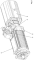
Figur 1 ist ein erfindungsgemäßer Elektromotor im Zusammenbau gezeigt. - In der
Figur 2 ist der erfindungsgemäße Elektromotor mit abgezogener Lüfterhaube 5 gezeigt. - In der
Figur 3 ist die Befestigung der Lüfterhaube 5 mittels Nutenstein 3 vergrößert dargestellt. - Der Elektromotor weist an seinem axialen Ende eine Welle auf zum Antreiben einer mechanischen Last. Das gesamte Gehäuse des Elektromotors umfasst das Motorgehäuse 1 und das daran befestigte Lagerschild 2, das auch als B-Lagerschild bezeichenbar ist. Mit diesem ist die Lüfterhaube 5 lösbar verbunden. Die Lüfterhaube 5 bildet einerseits Gehäusefunktion für die sich in ihrem Innern befindenden Komponenten, andererseits lenkt sie den Luftstrom derart auf das Gehäuse des Elektromotors, dass eine Außenkühlung für den Elektromotor vorhanden ist. Je nach Variante ist der Elektromotor mit Lüfter, Geber und/oder Bremse ausrüstbar, wobei diese Komponenten axial hintereinander angeordnet sind. Dazu sind dann auch verschieden lange Lüfterhauben innerhalb der Baureihe von Elektromotoren vorgesehen.
- Die Gussform für das Lagerschild wird derart ausgeführt, dass im Lagerschild 2 Ausnehmungen zum Einbringen der Nutensteine 3 vorgesehen werden, wobei die Ausnehmungen in axialer Richtung derart offen sind, dass der Nutenstein 3 jeweils axial einbringbar und auch wieder herausnehmbar ist. In radialer Richtung sind die Ausnehmungen jeweils derart offen, dass die Nutensteine 3 in der Ausnehmung gehalten sind, aber die Schraubengewinde der Schrauben 4 hindurchpasst. Die Lüfterhaube 5 weist an ihrem motorseitigen Ende ebenfalls schlitzförmige Ausnehmungen auf, durch die die Schraubengewindestifte der Schrauben 4 hindurchpassen. Somit ist die Lüfterhaube 5 auf die Schraubengewindestifte aufsteckbar. Durch Anziehen der Schrauben drücken die Nutensteine und die Schraubenköpfe der Schrauben 4 Lüfterhaube und Lagerschild 2 aufeinander. Somit sind Lüfterhaube und Lagerschild 2 kraftschlüssig verbunden.
- Besonders wesentlich ist bei dem Fertigen des Lagerschildes 2, dass die Ausnehmungen zum Einbringen der Nutensteine 3 in axialer Richtung orientiert und offen sind. Denn solche Ausnehmungen sind beim Gießen einfach und kostengünstig herstellbar. Im Gegensatz dazu wären radial gerichtete Ausnehmungen nur aufwendig und kostspielig herstellbar und würden darüber hinaus ein in einer Vorrichtung gleichzeitiges Gießen mehrerer Lagerschilde 2 unmöglich machen oder zumindest erschweren. Wesentlich ist dabei auch, dass zur stabilen Befestigung der Lüfterhaube am Lagerschild am Umfang vier Befestigungspunkte in im Wesentlichen gleichförmigem Abstand benötigt werden. Vier radial gerichtete Ausnehmungen würden also vier Entformungsrichtungen bedingen.
Bei der Erfindung hingegen sind die Ausnehmungen axial gerichtet und bedingen daher nur eine Entformungsrichtung. Somit ist die Gussform und der Gießvorgang in einfacher und kostengünstiger Weise ausführbar. - Wesentlich ist auch, dass mit diesem erfindungsgemäßen Elektromotor ein Lagerschild geschaffen wird, das die Nachrüstbarkeit verbessert und kostengünstiger macht. Beispielsweise bestellt ein Kunde aus der Baureihe des Herstellers einen Elektromotor ohne Lüfter und Lüfterhaube. Nach Montage und Inbetriebnahme stellt er des Öfteren fest, dass die Betriebs-Temperaturen des Elektromotors kritische Werte übersteigen. Bei Motoren nach Stand der Technik, also mit Befestigung durch Schrauben, müssen in aufwendiger Weise Gewindebohrungen am Umfang des Lagerschildes nachträglich angebracht werden. Bei der Erfindung hingegen sind die Ausnehmungen zur Aufnahme von Nutensteinen bei der gesamten Baureihe sowieso vorhanden, ohne dass Kosten erhöht sind, da eine Form und damit eine Sorte von Lagerschilden für Elektromotoren mit und für Elektromotoren ohne Lüfter verwendet werden. Der Kunde kann sogar mittels ungelernter Arbeiter eine nachbestellte Lüfterhaube in kostengünstiger Weise montieren.
- Bei weiteren erfindungsgemäßen Ausführungsbeispielen werden statt vier Befestigungspunkten am Umfang drei, fünf, sechs oder mehr Befestigungspunkte verwendet, so dass der Umfangswinkel zwischen zwei am Umfang benachbarten Nutensteinen 120° nicht überschreitet.
- Die genannten Ausnehmungen werden in allen Lagerschilden für Elektromotoren einer Baugröße gleich ausgeführt. Somit ist eine Schnittstelle innerhalb einer Baureihe von Elektromotoren, die mindestens eine Baugröße umfasst, geschaffen, ohne dass Kosten erhöht worden sind. Wie beschrieben, ist bei Nachrüstungen Zusatzaufwand einsparbar. Außerdem ist der Aufwand bei Demontage, beispielsweise im Zusammenhang mit Reparaturen oder Wartungstätigkeiten, vermindert.
-
- 1
- Motorgehäuse
- 2
- Lagerschild
- 3
- Nutenstein
- 4
- Schraube
- 5
- Lüfterhaube
- C
- Luftspalt
Claims (13)
- Elektromotor, umfassend ein als Lagerschild (2) fungierendes Gehäuseteil und eine Lüfterhaube (5),
wobei die Lüfterhaube (5) am Gehäuseteil kraftschlüssig lösbar befestigbar ist,
dadurch gekennzeichnet, dass
zur lösbaren Befestigung der Lüfterhaube (5) am Gehäuseteil ein oder mehrere Nutensteine (3) in einer beim Gießen hergestellte Ausnehmung des Gehäuseteils vorgesehen sind,
wobei die Lüfterhaube (5) an ihrem motorseitigen Ende schlitzförmige Ausnehmungen aufweist, durch die Schraubengewindestifte von Schrauben (4) hindurchpassen,
wobei die Lüfterhaube (5) auf die Schraubengewindestifte aufsteckbar ist,
wobei durch Anziehen der Schrauben (4) die Nutensteine (3) und die Schraubenköpfe der Schrauben (4) die Lüfterhaube (5) und das Gehäuseteil aufeinanderdrücken. - Elektromotor nach Anspruch 1,
dadurch gekennzeichnet, dass
Kühlluft zwischen Gehäuseteil und Lüfterhaube, insbesondere durch einen Spalt (C), austritt und als Außenkühlung des Gehäuses vorgesehen ist. - Elektromotor nach mindestens einem der vorangegangenen Ansprüche,
dadurch gekennzeichnet, dass
zur lösbaren Befestigung Schrauben (4) mit jeweiligen Nutensteinen (3) derart zusammenwirken, dass die Lüfterhaube (5) zumindest kraftschlüssig am Gehäuseteil befestigt ist. - Elektromotor nach mindestens einem der vorangegangenen Ansprüche,
dadurch gekennzeichnet, dass
die Lüfterhaube (5) Ausnehmungen für die Schrauben (4) umfasst. - Elektromotor nach mindestens einem der vorangegangenen Ansprüche,
dadurch gekennzeichnet, dass
am Umfang des Gehäuseteils mehrere Nutensteine (3) vorgesehen sind, wobei der größte Umfangswinkel zwischen zwei am Umfang benachbarten Nutensteinen (3) 120° nicht überschreitet. - Elektromotor nach mindestens einem der vorangegangenen Ansprüche,
dadurch gekennzeichnet, dass
am Umfang des Gehäuseteils vier Nutensteine (3) vorgesehen sind, wobei der Umfangswinkel zwischen zwei am Umfang benachbarten Nutensteinen (3) im Wesentlichen 90° beträgt. - Elektromotor nach mindestens einem der vorangegangenen Ansprüche,
dadurch gekennzeichnet, dass
die Lüfterhaube (5) einen größeren größten Außendurchmesser aufweist als der größte Außendurchmesser des Elektromotors. - Baureihe,
umfassend mindestens eine Baugröße, die jeweils mehrere Varianten von Elektromotoren nach mindestens einem der vorangegangenen Ansprüchen umfasst, die zumindest ein Gehäuseteil, insbesondere Lagerschild, und eine Lüfterhaube (5) umfassen, wobei die Lüfterhaube (5) am Gehäuseteil lösbar befestigbar ist,
dadurch gekennzeichnet, dass
alle Varianten einer Baugröße eine Schnittstelle zur lösbaren Befestigung eines weiteren Teils aufweisen. - Baureihe nach Anspruch 8,
dadurch gekennzeichnet, dass
die Schnittstelle mittels Ausnehmungen gebildet ist, die beim Gießen hergestellt werden, insbesondere unter Anwendung einer einzigen Entformungsrichtung. - Baureihe nach mindestens einem der vorangegangenen Ansprüche,
dadurch gekennzeichnet, dass
die Ausnehmungen zum Einbringen von Nutensteinen (3) in axialer Richtung gestaltet vorgesehen sind. - Baureihe nach mindestens einem der vorangegangenen Ansprüche,
dadurch gekennzeichnet, dass
die Baureihe verschiedene Elektromotoren, wie Synchron- und Asynchronmotoren oder dergleichen, umfasst. - Baureihe nach mindestens einem der vorangegangenen Ansprüche,
dadurch gekennzeichnet, dass
die Varianten von Elektromotoren mit oder ohne Lüfter, Geber, Bremse ausgestattet sind. - Baureihe nach mindestens einem der vorangegangenen Ansprüche,
dadurch gekennzeichnet, dass
die axiale Länge der Lüfterhaube (5) je nach Variante verschieden lang ausgeführt ist.
Applications Claiming Priority (3)
| Application Number | Priority Date | Filing Date | Title |
|---|---|---|---|
| DE10203406A DE10203406C2 (de) | 2002-01-28 | 2002-01-28 | Elektromotor und Baureihe |
| DE10203406 | 2002-01-28 | ||
| PCT/EP2002/014562 WO2003065547A1 (de) | 2002-01-28 | 2002-12-19 | Elektromotor und baureihe |
Publications (2)
| Publication Number | Publication Date |
|---|---|
| EP1472773A1 EP1472773A1 (de) | 2004-11-03 |
| EP1472773B1 true EP1472773B1 (de) | 2019-05-22 |
Family
ID=7713309
Family Applications (1)
| Application Number | Title | Priority Date | Filing Date |
|---|---|---|---|
| EP02795231.6A Expired - Lifetime EP1472773B1 (de) | 2002-01-28 | 2002-12-19 | Elektromotor und baureihe |
Country Status (3)
| Country | Link |
|---|---|
| EP (1) | EP1472773B1 (de) |
| DE (1) | DE10203406C2 (de) |
| WO (1) | WO2003065547A1 (de) |
Cited By (2)
| Publication number | Priority date | Publication date | Assignee | Title |
|---|---|---|---|---|
| EP4002655A1 (de) | 2020-11-24 | 2022-05-25 | Siemens Aktiengesellschaft | Elektromotor und roboter mit elektromotor |
| WO2022242902A1 (de) * | 2021-05-19 | 2022-11-24 | Sew-Eurodrive Gmbh & Co. Kg | Elektromotor mit statorgehäuse, lagerflansch und lüfterhaube zur aufnahme eines lüfters |
Families Citing this family (4)
| Publication number | Priority date | Publication date | Assignee | Title |
|---|---|---|---|---|
| DE102004015241B4 (de) * | 2004-03-29 | 2017-05-11 | Siemens Aktiengesellschaft | Luftgekühlte elektrische Maschine |
| DE102004046473B4 (de) | 2004-09-23 | 2023-04-27 | Sew-Eurodrive Gmbh & Co Kg | Linearmotor |
| DE102005016905B3 (de) * | 2005-04-12 | 2006-11-30 | Sew-Eurodrive Gmbh & Co. Kg | Elektromotor mit Lüfter und zugehöriger Lüfterhaube |
| DE102015009540A1 (de) * | 2015-07-28 | 2017-02-02 | Sew-Eurodrive Gmbh & Co Kg | Elektromotor mit Lüfter, Lüfterhaube, Motorgehäuse, aufweisend Gehäuseteil, Flanschteil und Statorgehäuse |
Citations (1)
| Publication number | Priority date | Publication date | Assignee | Title |
|---|---|---|---|---|
| DE3842442A1 (de) * | 1988-02-29 | 1989-09-07 | Heinz Georg Baus | Lueftungsanordnung |
Family Cites Families (13)
| Publication number | Priority date | Publication date | Assignee | Title |
|---|---|---|---|---|
| DE1912104U (de) * | 1965-01-14 | 1965-03-18 | Heinrich Hinz Elmasch Und Appb | Elektromotor. |
| US3527970A (en) * | 1968-10-09 | 1970-09-08 | Emerson Electric Co | Electric motor construction and ventilating system |
| DE7731136U1 (de) * | 1977-10-07 | 1978-09-28 | Siemens Ag, 1000 Berlin Und 8000 Muenchen | Elektrische maschine mit einem fremdluefter |
| FR2416386A1 (fr) * | 1978-02-07 | 1979-08-31 | Leroy Somer Moteurs | Frein adaptable a un moteur electrique, procede pour son montage et moteur-frein en resultant |
| DE3635327A1 (de) * | 1986-10-17 | 1988-04-28 | Felten & Guilleaume Energie | Luefter mit luefterhaube fuer geraeuscharme drehstrommotoren |
| DE3836147C2 (de) * | 1988-10-23 | 1996-03-21 | Ltg Lufttechnische Gmbh | Reinraumdecke |
| DE9305174U1 (de) * | 1993-04-05 | 1993-11-04 | Franz Morat KG Elektro-Feinmechanik & Maschinenbau (GmbH & Co), 79871 Eisenbach | Drehstrom-Asynchronmotor mit Frequenzumrichter |
| DE29700643U1 (de) * | 1997-01-15 | 1997-03-13 | Siemens AG, 80333 München | Entwärmungskonzept für ein elektrisches Antriebssystem |
| CA2212354C (en) * | 1997-07-31 | 2000-07-11 | Ibm Canada Limited - Ibm Canada Limitee | Method for heap management of fixed sized objects using pages |
| DE19808797C2 (de) * | 1998-03-03 | 2002-05-08 | Felten & Guilleaume Ag | Bausatz für Elektromotoren |
| EP0942513A3 (de) * | 1998-03-10 | 2001-02-07 | ATB Austria Antriebstechnik Aktiengesellschaft | Elektromotor |
| DE19924735A1 (de) * | 1999-05-31 | 2001-03-15 | Sew Eurodrive Gmbh & Co | Baureihe von Elektromotoren mit Drehzahlrückführung und Elektromotor mit Drehzahlrückführung |
| DE19926542B4 (de) * | 1999-06-10 | 2016-06-09 | Sew-Eurodrive Gmbh & Co Kg | Steckverbindereinheit für einen Anschlußkasten eines Elektromotors |
-
2002
- 2002-01-28 DE DE10203406A patent/DE10203406C2/de not_active Expired - Lifetime
- 2002-12-19 EP EP02795231.6A patent/EP1472773B1/de not_active Expired - Lifetime
- 2002-12-19 WO PCT/EP2002/014562 patent/WO2003065547A1/de not_active Ceased
Patent Citations (1)
| Publication number | Priority date | Publication date | Assignee | Title |
|---|---|---|---|---|
| DE3842442A1 (de) * | 1988-02-29 | 1989-09-07 | Heinz Georg Baus | Lueftungsanordnung |
Cited By (2)
| Publication number | Priority date | Publication date | Assignee | Title |
|---|---|---|---|---|
| EP4002655A1 (de) | 2020-11-24 | 2022-05-25 | Siemens Aktiengesellschaft | Elektromotor und roboter mit elektromotor |
| WO2022242902A1 (de) * | 2021-05-19 | 2022-11-24 | Sew-Eurodrive Gmbh & Co. Kg | Elektromotor mit statorgehäuse, lagerflansch und lüfterhaube zur aufnahme eines lüfters |
Also Published As
| Publication number | Publication date |
|---|---|
| WO2003065547A1 (de) | 2003-08-07 |
| DE10203406A1 (de) | 2003-08-07 |
| DE10203406C2 (de) | 2003-12-24 |
| EP1472773A1 (de) | 2004-11-03 |
Similar Documents
| Publication | Publication Date | Title |
|---|---|---|
| EP0892724B1 (de) | Befestigungsvorrichtung | |
| EP1389824A1 (de) | Elektromaschinensystem | |
| WO2012059154A2 (de) | Elektromotor, bausatz und verfahren zur herstellung | |
| DE10203406C2 (de) | Elektromotor und Baureihe | |
| DE102010049622A1 (de) | Elektrische Antriebseinheit für ein Kraftfahrzeug | |
| EP0454664B1 (de) | Elektrische maschine mit vertikaler welle | |
| EP3948028B1 (de) | Getriebe mit lüfteranordnung | |
| DE102021002635A1 (de) | Antrieb, aufweisend ein von einem Elektromotor angetriebenes Getriebe | |
| EP4118361B1 (de) | Getriebe mit lüfteranordnung | |
| DE102022001426A1 (de) | Elektromotor mit Statorgehäuse, Lagerflansch und Lüfterhaube zur Aufnahme eines Lüfters | |
| DE202013104630U1 (de) | E-Bike | |
| WO2025037027A1 (de) | Elektromotor | |
| DE3635987C2 (de) | ||
| DE102005009607B4 (de) | Antrieb und Verfahren zur Überwachung dieses Antriebs | |
| DE102004015241B4 (de) | Luftgekühlte elektrische Maschine | |
| EP0942513A2 (de) | Elektromotor | |
| EP0610766A1 (de) | Pumpenaggregat mit einem drehzahlregelbaren Elektromotor | |
| DE102023004596A1 (de) | Elektromotor mit Lüfter und Lüfterhaube | |
| EP0942514B1 (de) | Elektromotor mit Flanschring | |
| EP3163725A1 (de) | Maschineneinheit, teilstück und zwischenelement sowie verfahren zum verbinden und/oder lösen einer anschlussleitung | |
| DE2845666A1 (de) | Elektrische maschine | |
| DE102023004610A1 (de) | Elektromotor mit Lüfter und Lüfterhaube | |
| WO2025140808A1 (de) | Elektromotor mit lüfterhaube und ersten winkelsensor | |
| DE102020002950A1 (de) | Antrieb, aufweisend einen Elektromotor mit Rotorwelle, Winkelsensor und Haubenteil sowie Anschlussmodul, und Verfahren zum Herstellen eines Antriebs | |
| DE102023203538A1 (de) | Sicherungselement für einen Elektromotor |
Legal Events
| Date | Code | Title | Description |
|---|---|---|---|
| PUAI | Public reference made under article 153(3) epc to a published international application that has entered the european phase |
Free format text: ORIGINAL CODE: 0009012 |
|
| 17P | Request for examination filed |
Effective date: 20040830 |
|
| AK | Designated contracting states |
Kind code of ref document: A1 Designated state(s): AT BE BG CH CY CZ DE DK EE ES FI FR GB GR IE IT LI LU MC NL PT SE SI SK TR |
|
| AX | Request for extension of the european patent |
Extension state: AL LT LV MK RO |
|
| STAA | Information on the status of an ep patent application or granted ep patent |
Free format text: STATUS: EXAMINATION IS IN PROGRESS |
|
| 17Q | First examination report despatched |
Effective date: 20180621 |
|
| REG | Reference to a national code |
Ref country code: DE Ref legal event code: R079 Ref document number: 50216339 Country of ref document: DE Free format text: PREVIOUS MAIN CLASS: H02K0009140000 Ipc: H02K0005200000 |
|
| GRAP | Despatch of communication of intention to grant a patent |
Free format text: ORIGINAL CODE: EPIDOSNIGR1 |
|
| STAA | Information on the status of an ep patent application or granted ep patent |
Free format text: STATUS: GRANT OF PATENT IS INTENDED |
|
| RIC1 | Information provided on ipc code assigned before grant |
Ipc: H02K 7/102 19680901ALI20181024BHEP Ipc: H02K 5/20 19680901AFI20181024BHEP Ipc: H02K 11/00 19680901ALI20181024BHEP Ipc: H02K 9/14 19680901ALI20181024BHEP |
|
| INTG | Intention to grant announced |
Effective date: 20181114 |
|
| RIC1 | Information provided on ipc code assigned before grant |
Ipc: H02K 5/20 20060101AFI20181024BHEP Ipc: H02K 11/00 20160101ALI20181024BHEP Ipc: H02K 9/14 20060101ALI20181024BHEP Ipc: H02K 7/102 20060101ALI20181024BHEP |
|
| GRAJ | Information related to disapproval of communication of intention to grant by the applicant or resumption of examination proceedings by the epo deleted |
Free format text: ORIGINAL CODE: EPIDOSDIGR1 |
|
| STAA | Information on the status of an ep patent application or granted ep patent |
Free format text: STATUS: EXAMINATION IS IN PROGRESS |
|
| INTC | Intention to grant announced (deleted) | ||
| GRAP | Despatch of communication of intention to grant a patent |
Free format text: ORIGINAL CODE: EPIDOSNIGR1 |
|
| STAA | Information on the status of an ep patent application or granted ep patent |
Free format text: STATUS: GRANT OF PATENT IS INTENDED |
|
| GRAS | Grant fee paid |
Free format text: ORIGINAL CODE: EPIDOSNIGR3 |
|
| GRAA | (expected) grant |
Free format text: ORIGINAL CODE: 0009210 |
|
| STAA | Information on the status of an ep patent application or granted ep patent |
Free format text: STATUS: THE PATENT HAS BEEN GRANTED |
|
| INTG | Intention to grant announced |
Effective date: 20190329 |
|
| AK | Designated contracting states |
Kind code of ref document: B1 Designated state(s): AT BE BG CH CY CZ DE DK EE ES FI FR GB GR IE IT LI LU MC NL PT SE SI SK TR |
|
| REG | Reference to a national code |
Ref country code: GB Ref legal event code: FG4D Free format text: NOT ENGLISH |
|
| REG | Reference to a national code |
Ref country code: CH Ref legal event code: EP Ref country code: CH Ref legal event code: NV Representative=s name: HEPP WENGER RYFFEL AG, CH |
|
| REG | Reference to a national code |
Ref country code: IE Ref legal event code: FG4D Free format text: LANGUAGE OF EP DOCUMENT: GERMAN |
|
| REG | Reference to a national code |
Ref country code: DE Ref legal event code: R096 Ref document number: 50216339 Country of ref document: DE |
|
| REG | Reference to a national code |
Ref country code: AT Ref legal event code: REF Ref document number: 1137277 Country of ref document: AT Kind code of ref document: T Effective date: 20190615 |
|
| REG | Reference to a national code |
Ref country code: SE Ref legal event code: TRGR |
|
| REG | Reference to a national code |
Ref country code: NL Ref legal event code: FP |
|
| PG25 | Lapsed in a contracting state [announced via postgrant information from national office to epo] |
Ref country code: ES Free format text: LAPSE BECAUSE OF FAILURE TO SUBMIT A TRANSLATION OF THE DESCRIPTION OR TO PAY THE FEE WITHIN THE PRESCRIBED TIME-LIMIT Effective date: 20190522 Ref country code: FI Free format text: LAPSE BECAUSE OF FAILURE TO SUBMIT A TRANSLATION OF THE DESCRIPTION OR TO PAY THE FEE WITHIN THE PRESCRIBED TIME-LIMIT Effective date: 20190522 Ref country code: PT Free format text: LAPSE BECAUSE OF FAILURE TO SUBMIT A TRANSLATION OF THE DESCRIPTION OR TO PAY THE FEE WITHIN THE PRESCRIBED TIME-LIMIT Effective date: 20190922 |
|
| PG25 | Lapsed in a contracting state [announced via postgrant information from national office to epo] |
Ref country code: BG Free format text: LAPSE BECAUSE OF FAILURE TO SUBMIT A TRANSLATION OF THE DESCRIPTION OR TO PAY THE FEE WITHIN THE PRESCRIBED TIME-LIMIT Effective date: 20190822 Ref country code: GR Free format text: LAPSE BECAUSE OF FAILURE TO SUBMIT A TRANSLATION OF THE DESCRIPTION OR TO PAY THE FEE WITHIN THE PRESCRIBED TIME-LIMIT Effective date: 20190823 |
|
| PG25 | Lapsed in a contracting state [announced via postgrant information from national office to epo] |
Ref country code: EE Free format text: LAPSE BECAUSE OF FAILURE TO SUBMIT A TRANSLATION OF THE DESCRIPTION OR TO PAY THE FEE WITHIN THE PRESCRIBED TIME-LIMIT Effective date: 20190522 Ref country code: SK Free format text: LAPSE BECAUSE OF FAILURE TO SUBMIT A TRANSLATION OF THE DESCRIPTION OR TO PAY THE FEE WITHIN THE PRESCRIBED TIME-LIMIT Effective date: 20190522 Ref country code: CZ Free format text: LAPSE BECAUSE OF FAILURE TO SUBMIT A TRANSLATION OF THE DESCRIPTION OR TO PAY THE FEE WITHIN THE PRESCRIBED TIME-LIMIT Effective date: 20190522 Ref country code: DK Free format text: LAPSE BECAUSE OF FAILURE TO SUBMIT A TRANSLATION OF THE DESCRIPTION OR TO PAY THE FEE WITHIN THE PRESCRIBED TIME-LIMIT Effective date: 20190522 |
|
| REG | Reference to a national code |
Ref country code: DE Ref legal event code: R097 Ref document number: 50216339 Country of ref document: DE |
|
| PLBE | No opposition filed within time limit |
Free format text: ORIGINAL CODE: 0009261 |
|
| STAA | Information on the status of an ep patent application or granted ep patent |
Free format text: STATUS: NO OPPOSITION FILED WITHIN TIME LIMIT |
|
| PG25 | Lapsed in a contracting state [announced via postgrant information from national office to epo] |
Ref country code: TR Free format text: LAPSE BECAUSE OF FAILURE TO SUBMIT A TRANSLATION OF THE DESCRIPTION OR TO PAY THE FEE WITHIN THE PRESCRIBED TIME-LIMIT Effective date: 20190522 |
|
| 26N | No opposition filed |
Effective date: 20200225 |
|
| PG25 | Lapsed in a contracting state [announced via postgrant information from national office to epo] |
Ref country code: SI Free format text: LAPSE BECAUSE OF FAILURE TO SUBMIT A TRANSLATION OF THE DESCRIPTION OR TO PAY THE FEE WITHIN THE PRESCRIBED TIME-LIMIT Effective date: 20190522 |
|
| REG | Reference to a national code |
Ref country code: BE Ref legal event code: MM Effective date: 20191231 |
|
| PG25 | Lapsed in a contracting state [announced via postgrant information from national office to epo] |
Ref country code: MC Free format text: LAPSE BECAUSE OF FAILURE TO SUBMIT A TRANSLATION OF THE DESCRIPTION OR TO PAY THE FEE WITHIN THE PRESCRIBED TIME-LIMIT Effective date: 20190522 |
|
| PG25 | Lapsed in a contracting state [announced via postgrant information from national office to epo] |
Ref country code: IE Free format text: LAPSE BECAUSE OF NON-PAYMENT OF DUE FEES Effective date: 20191219 Ref country code: LU Free format text: LAPSE BECAUSE OF NON-PAYMENT OF DUE FEES Effective date: 20191219 |
|
| PG25 | Lapsed in a contracting state [announced via postgrant information from national office to epo] |
Ref country code: BE Free format text: LAPSE BECAUSE OF NON-PAYMENT OF DUE FEES Effective date: 20191231 |
|
| PG25 | Lapsed in a contracting state [announced via postgrant information from national office to epo] |
Ref country code: CY Free format text: LAPSE BECAUSE OF FAILURE TO SUBMIT A TRANSLATION OF THE DESCRIPTION OR TO PAY THE FEE WITHIN THE PRESCRIBED TIME-LIMIT Effective date: 20190522 |
|
| PGFP | Annual fee paid to national office [announced via postgrant information from national office to epo] |
Ref country code: NL Payment date: 20211116 Year of fee payment: 20 Ref country code: GB Payment date: 20211104 Year of fee payment: 20 Ref country code: FR Payment date: 20211116 Year of fee payment: 20 Ref country code: SE Payment date: 20211110 Year of fee payment: 20 Ref country code: AT Payment date: 20211207 Year of fee payment: 20 Ref country code: DE Payment date: 20211231 Year of fee payment: 20 |
|
| PGFP | Annual fee paid to national office [announced via postgrant information from national office to epo] |
Ref country code: IT Payment date: 20211110 Year of fee payment: 20 |
|
| PGFP | Annual fee paid to national office [announced via postgrant information from national office to epo] |
Ref country code: CH Payment date: 20220301 Year of fee payment: 20 |
|
| REG | Reference to a national code |
Ref country code: DE Ref legal event code: R071 Ref document number: 50216339 Country of ref document: DE |
|
| REG | Reference to a national code |
Ref country code: NL Ref legal event code: MK Effective date: 20221218 |
|
| REG | Reference to a national code |
Ref country code: CH Ref legal event code: PL |
|
| REG | Reference to a national code |
Ref country code: GB Ref legal event code: PE20 Expiry date: 20221218 |
|
| PG25 | Lapsed in a contracting state [announced via postgrant information from national office to epo] |
Ref country code: GB Free format text: LAPSE BECAUSE OF EXPIRATION OF PROTECTION Effective date: 20221218 |
|
| REG | Reference to a national code |
Ref country code: SE Ref legal event code: EUG |
|
| REG | Reference to a national code |
Ref country code: AT Ref legal event code: MK07 Ref document number: 1137277 Country of ref document: AT Kind code of ref document: T Effective date: 20221219 |