EP0854560A1 - Entwärmungskonzept für ein elektrisches Antriebssystem - Google Patents
Entwärmungskonzept für ein elektrisches Antriebssystem Download PDFInfo
- Publication number
- EP0854560A1 EP0854560A1 EP98100161A EP98100161A EP0854560A1 EP 0854560 A1 EP0854560 A1 EP 0854560A1 EP 98100161 A EP98100161 A EP 98100161A EP 98100161 A EP98100161 A EP 98100161A EP 0854560 A1 EP0854560 A1 EP 0854560A1
- Authority
- EP
- European Patent Office
- Prior art keywords
- drive system
- motor
- housing
- fan
- ext
- Prior art date
- Legal status (The legal status is an assumption and is not a legal conclusion. Google has not performed a legal analysis and makes no representation as to the accuracy of the status listed.)
- Withdrawn
Links
- 230000017525 heat dissipation Effects 0.000 title description 5
- 238000001816 cooling Methods 0.000 claims abstract description 37
- 238000009423 ventilation Methods 0.000 claims description 20
- 230000008878 coupling Effects 0.000 claims description 6
- 238000010168 coupling process Methods 0.000 claims description 6
- 238000005859 coupling reaction Methods 0.000 claims description 6
- 239000003795 chemical substances by application Substances 0.000 description 20
- 238000010586 diagram Methods 0.000 description 2
- 239000011810 insulating material Substances 0.000 description 2
- 238000010276 construction Methods 0.000 description 1
- 239000002826 coolant Substances 0.000 description 1
- 238000001514 detection method Methods 0.000 description 1
- 239000000835 fiber Substances 0.000 description 1
- 238000009413 insulation Methods 0.000 description 1
- 230000010354 integration Effects 0.000 description 1
- 238000000034 method Methods 0.000 description 1
- 238000011084 recovery Methods 0.000 description 1
- 230000001360 synchronised effect Effects 0.000 description 1
Images

Classifications
-
- H—ELECTRICITY
- H02—GENERATION; CONVERSION OR DISTRIBUTION OF ELECTRIC POWER
- H02K—DYNAMO-ELECTRIC MACHINES
- H02K5/00—Casings; Enclosures; Supports
- H02K5/04—Casings or enclosures characterised by the shape, form or construction thereof
- H02K5/18—Casings or enclosures characterised by the shape, form or construction thereof with ribs or fins for improving heat transfer
-
- H—ELECTRICITY
- H02—GENERATION; CONVERSION OR DISTRIBUTION OF ELECTRIC POWER
- H02K—DYNAMO-ELECTRIC MACHINES
- H02K11/00—Structural association of dynamo-electric machines with electric components or with devices for shielding, monitoring or protection
- H02K11/30—Structural association with control circuits or drive circuits
- H02K11/33—Drive circuits, e.g. power electronics
-
- H—ELECTRICITY
- H02—GENERATION; CONVERSION OR DISTRIBUTION OF ELECTRIC POWER
- H02K—DYNAMO-ELECTRIC MACHINES
- H02K9/00—Arrangements for cooling or ventilating
- H02K9/14—Arrangements for cooling or ventilating wherein gaseous cooling medium circulates between the machine casing and a surrounding mantle
-
- H—ELECTRICITY
- H02—GENERATION; CONVERSION OR DISTRIBUTION OF ELECTRIC POWER
- H02K—DYNAMO-ELECTRIC MACHINES
- H02K5/00—Casings; Enclosures; Supports
- H02K5/04—Casings or enclosures characterised by the shape, form or construction thereof
- H02K5/20—Casings or enclosures characterised by the shape, form or construction thereof with channels or ducts for flow of cooling medium
- H02K5/207—Casings or enclosures characterised by the shape, form or construction thereof with channels or ducts for flow of cooling medium with openings in the casing specially adapted for ambient air
Definitions
- the invention relates to an electric drive system with motor, integrated converter and integrated drive electronics and with means for forced ventilation.
- the drive electronics are used for decentralized drive concepts (Drive control and power electronics) increasingly in integrated the motor. For this purpose, direct current, Synchronous, asynchronous machines and stepper motors are used.
- the power electronics and the resulting Power loss depends on the motor power, the machine type used, the rectifier or converter type, the circuit breaker type (thyristor, transistor, etc.) The fact whether the motor is operated in 1, 2 or 4 quadrant mode or whether an active or passive energy recovery he follows. The resulting power loss also depends also on the execution of the drive control.
- This simplest cooling concept is used for drives small power loss used.
- a possible embodiment is shown with reference to the illustration of FIG 2, after which an add-on housing AG is attached to a motor M, which includes the AE drive electronics.
- the vent housing AG has cooling fins KR for ventilation, which enlarge the surface of the attachment housing and thus allow greater heat dissipation.
- the motor shaft is MW through the AG drive housing with the AE drive electronics and a fan wheel LR is attached to the drive shaft MW.
- This fan wheel LR is driven by the motor and creates an airflow that improves cooling of the Add-on housing causes.
- the amount of air flow is one Function of the engine speed, which is especially true with engines low speed brings problems with it. Add to that the Disadvantage that if the engine stops or fails, no airflow is generated. This well-known concept self-ventilation is shown in the illustration in FIG. 3 shown.
- the object of the present invention is therefore an electrical To create drive system with forced ventilation, which needs minimal fan power and also a minimal one Construction volume enables.
- this object is achieved by an electric drive system with a motor, an integrated converter and integrated drive electronics and by means for external ventilation, in that at least one separate fan motor LM is integrated into the housing of the drive system for external ventilation, the fan motor shaft LMW of which is outside the housing of the Drive system arranged respective external fan wheel LR ext drives.
- the degree of heat dissipation that can be achieved is increased still further, and the required fan power is thus additionally reduced.
- a further internal fan wheel LR int is provided on the B side B2 of each fan motor (LM), by means of which air swirl can be generated in the housing of the drive system.
- the drive electronics via an add-on housing in the drive system integrated and each fan motor in the attachment housing mentioned so integrated that the fan motor via the drive electronics can be supplied with energy.
- a further advantageous embodiment of the electric drive system according to the present invention is characterized in that the attachment housing AG is attached to the B-side motor end shield and each fan motor LM, on the one hand, the associated external fan wheel LR ext, on the other hand, is arranged on the B side B of the attachment housing AG .
- Another advantageous embodiment of the electric drive system according to the present invention describes advantageous options for carrying out the fan motor shaft through the housing of the drive system.
- This advantageous embodiment is characterized in that each fan motor shaft LMW is guided outwards to the associated external fan wheel LR ext via a shaft seal or drives a second shaft via a clutch on which the associated external fan wheel LR ext is arranged.
- the cooling concept according to the present invention can also be used when the motor shaft of the motor has to be led out through the attachment housing on the B side.
- a single fan motor LM is provided, which is designed as a hollow shaft motor
- the associated external fan wheel LR ext is designed as a hollow shaft fan wheel, which can be driven by means of a belt or gear coupling.
- a further possibility is created to use the heat dissipation concept also in motors with a motor shaft leading out through the attachment housing on both sides.
- This is achieved in that a single fan motor LM is provided, which is arranged off-center on the B-side B of the motor M, and the associated external fan wheel LR ext is designed as a hollow shaft fan wheel which can be driven by means of a belt or gear coupling.
- a first such advantageous exemplary embodiment is characterized in that the housing of the drive system on the B-side B has radial cooling fins KR radially , with air or the external fan wheels LR ext air B-side B being able to be axially sucked in and radially deflected such that a radial air flow can be guided radially via the radial cooling fins KR.
- Another such advantageous embodiment is characterized in that the housing of the drive system has axially distributed axial cooling fins or cooling channels KK axially and a hood H is arranged on the B-side B of the housing of the drive system so that the radial air flow axially over the axial cooling fins or in the axial cooling channels KK axially of the housing.
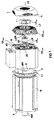
- FIG. 1 is an exploded view an electric drive system with motor M, integrated Converter and integrated drive electronics AE shown, which is forced ventilation according to the present invention enables.
- an electric motor M is shown, the Motor shaft MW A-side A is led out of the motor housing.
- B-sided B is an add-on housing AG for the integration of the drive electronics AE provided, which is on the B-sided Engine end shield is attached. This attachment housing AG is designed so that the interference contour (mounting format) of the motor M is injured as little as possible.
- the attachment housing AG preferably has a concept small length, which increases the volume of the electrical Drive system can be minimized.
- a separate LM fan motor integrated for the purpose of forced ventilation is also B-side B in the attachment housing AG arranged so that the fan motor shaft LMW the B-side B of the electric drive system, i.e. from the A-side A is arranged facing away.
- the fan motor shaft LMW of the fan motor LM is led to the outside through a bearing plate L of the mounting housing AG arranged on the B side and drives an external fan wheel LR ext .
- the fan motor shaft LMW can either be guided to the outside via a shaft seal with the appropriate degree of protection, or it can drive a second shaft via a coupling, which is guided to the outside via the end shield L with the corresponding degree of protection and drives the internal fan wheel LR ext .
- several fan motors, each with an assigned external fan wheel can be provided.
- an arrangement with only one fan motor LM is shown in the exemplary embodiment, which drives a single external fan wheel LR ext .
- the circuit breakers of the AE drive electronics are also advantageously mounted on the B side in the AG mounting housing.
- the bearing plate L of the attachment housing AG has radial cooling fins KR radially .
- the add-on housing AG has axial cooling channels KK axial .
- axial cooling fins could also be arranged distributed over the circumference of the attachment housing. Such a measure is also possible in addition.
- a hood H is attached on the B side, which has axial air inlet slots and radial air outlet slots.
- this hood H secures the external fan wheel LR ext , on the other hand it serves for the suitable guidance of an air flow LS.
- the external fan wheel LR ext now draws in air on the B side and redirects this air radially. Radially deflected air is guided radially on the end shield L2 via the radially arranged cooling fins KR. Since the circuit breakers of the drive electronics AE are also mounted on the B side, these circuit breakers give their heat loss to the end shield L preferably. This heat loss can be dissipated radially by the axially deflected air flow LS via the radial cooling fins KR. Thus, the radial cooling fins are mainly intended for the dissipation of the power unit's power loss (switching and forward losses of the circuit breakers).
- the hood on the housing B-side optimizes the guidance of the air flow LS in such a way that part of the radially deflected air flow exits through the radial air outlet slots of the cover H and the other part of the air flow LS is passed axially through the cover H via the attachment housing AG.
- This axially forwarded air flow is thus guided axially through the axial cooling channels KK or, if present, via axial cooling fins.
- These axial cooling channels KK axial or axial cooling fins are mainly used to dissipate the electronic power loss.
- the axial air flow mentioned can thus also be passed on over the surface of the motor M, the motor M likewise being able to have cooling fins or cooling channels. As a result, most of the heat generated in the motor M itself can be dissipated.
- the fan motor LM has a further internal fan wheel LR int on its B side B2, through which air swirling can be achieved within the attachment housing AG.
- This air turbulence can significantly improve the heat dissipation due to the heat exchanger principle. This has the advantage that the cooling concept according to the present invention enables a very small fan output.
- the cooling concept then used according to the present invention if the motor shaft MW B-side B through the attachment housing AG must be brought out.
- the LM fan motor can be designed as a hollow shaft motor and then an external hollow shaft fan wheel via belts or gears operate.
- a fan motor LM as in the embodiment according to the 1 is shown, arranged eccentrically and also via a belt or gear coupling Hollow shaft fan wheel drives.
- several eccentrically arranged fan motors with corresponding external and internal fan wheels can be used.
- the B-side end shield L1 of the motor M and the Drive electronics AE in the mounting housing AG is in the embodiment as shown in FIG 1 also a Insulation washer D made of a heat-insulating material (e.g. fiber optic amplifier plastic) provided to the power loss (Heat) of the motor M from the power loss of the drive electronics Decouple AE.
- a heat-insulating material e.g. fiber optic amplifier plastic
- the B-side end shield L1 of the motor M for Heat decoupling made of a heat insulating material is.
- Such an encoder system G arranged after the heat decoupling on the part of the attachment housing AG.
Landscapes
- Engineering & Computer Science (AREA)
- Power Engineering (AREA)
- Physics & Mathematics (AREA)
- Thermal Sciences (AREA)
- Microelectronics & Electronic Packaging (AREA)
- Motor Or Generator Cooling System (AREA)
- Control Of Electric Motors In General (AREA)
- Control Of Multiple Motors (AREA)
Abstract
Mit Hilfe der vorliegenden Erfindung wird eine Fremdbelüftung zur Entwärmung mit minimaler Lüfterleistung und minimalem Bauvolumen geschaffen. Dies wird erreicht, indem ein Lüftermotor (LM) in die Antriebselektronik (AE) integriert wird, welcher ein externes Lüfterrad (LRext) antreibt. Zusätzlich kann der Lüftermotor (LM) ein internes Lüfterrad (LRint) zur Luftverwirbelung im Gehäuse des elektrischen Antriebsystemes beinhalten. Auf diese Weise wird durch das Wärmetauscherprinzip die Verlustleistungsabfuhr wesentlich verbessert. Ein weiterer Vorteil besteht darin, daß auf einen Lüfterversorgungsspannungsanschluß verzichtet werden kann. <IMAGE>
Description
Die Erfindung bezieht sich auf ein elektrisches Antriebssystem
mit Motor, interiertem Umrichter und integrierter Antriebselektronik
sowie mit Mitteln zur Fremdbelüftung.
Für dezentrale Antriebskonzepte wird die Antriebselektronik
(Antriebsregelung und die Leistungselektronik) zunehmend in
den Motor integriert. Hierzu werden vorzugsweise Gleichstrom-,
Synchron-, Asynchronmaschinen und Schrittmotoren eingesetzt.
Die Leistungselektronik und die dadurch bedingt entstehende
Verlustleistung ist abhängig von der Motorleistung,
dem verwendeten Maschinentyp, dem Gleich- bzw. Umrichtertyp,
dem Leistungsschaltertyp (Thyristor, Transistor etc.) der
Tatsache, ob der Motor im 1, 2 oder 4 Quadrantenbetrieb betrieben
wird, oder ob eine aktive oder passive Energierückspeisung
erfolgt. Desweiteren hängt die entstehende Verlustleistung
auch von der Ausführung der Antriebsregelung ab.
Zur Abführung der Verlustleistung sind folgende Entwärmungskonzepte
bekannt.
Dieses einfachste Entwärmungskonzept wird bei Antrieben mit
kleiner Verlustleistung eingesetzt. Eine mögliche Ausführungsform
ist anhand der Darstellung nach FIG 2 gezeigt, wonach
an einem Motor M ein Anbaugehäuse AG angebracht ist,
welches unter anderem die Antriebselektronik AE beinhaltet.
Zur Entlüftung weist das Anbaugehäuse AG Kühlrippen KR auf,
welche die Oberfläche des Anbaugehäuses vergrößern und somit
eine größere Wärmeabfuhr ermöglichen.
Bei Antrieben mit größerer Verlustleistung und einem geeigneten
Drehzahl/Drehmoment-Profil, wird die Motorwelle MW durch
das Antriebsgehäuse AG mit der Antriebselektronik AE geführt
und auf der Antriebswelle MW ein Lüfterrad LR angebracht.
Dieses Lüfterrad LR wird durch den Motor mitangetrieben und
erzeugt einen Luftstrom, welcher eine verbesserte Kühlung des
Anbaugehäuses bewirkt. Dabei ist die Luftstrommenge eine
Funktion der Motordrehzahl, was vor allem bei Motoren mit
niedrigen Drehzahlen Probleme mitsichbringt. Hinzu kommt der
Nachteil, daß dann, wenn der Motor stillsteht oder ausfällt,
kein Luftstrom erzeugt wird. Dieses ebenfalls bekannte Konzept
der Eigenbelüftung ist in der Darstellung gemäß FIG 3
gezeigt.
Bei Antrieben mit größerer Verlustleistung und einem Drehzahl/Drehmoment-Profil,
für das eine Eigenbelüftung nicht
ausreicht, wird eine Fremdbelüftung vorgenommen. Dieses bekannte
Verfahren ist in der Darstellung gemäß FIG 4 gezeigt
und unterscheidet sich von der Eigenbelüftung dadurch, daß
das Lüfterrad LR nicht durch die Motorwelle MW, sondern durch
einen separaten Lüftermotor LM angetrieben wird. Dies hat zur
Folge, daß die Luftstrommenge keine Funktion der Motordrehzahl
mehr ist, wodurch die der Eigenbelüftung zugrundeliegende
Nachteile vermieden werden können.
Bei bisher bekannten Produkten mit Fremdbelüftung wird die
Verlustleistung über extern angebaute Lüfter abgeführt. Die
bekannten Antriebssysteme weisen jedoch den Nachteil auf, daß
durch den extern angebauten Lüfter ein hohes Bauvolumen entsteht,
ein zusätzlicher Lüfterversorgungsspannungsanschluß
notwendig wird und eine hohe Lüfterleistung erforderlich ist.
Aufgabe der vorliegenden Erfindung ist es daher, ein elektrisches
Antriebssystem mit Fremdbelüftung zu schaffen, welches
mit minimaler Lüfterleistung auskommt und zudem ein minimales
Bauvolumen ermöglicht.
Gemäß der vorliegenden Erfindung wird diese Aufgabe durch ein
elektrisches Antriebssystem mit Motor, integriertem Umrichter
und integrierter Antriebselektronik sowie mit Mitteln zur
Fremdbelüftung gelöst, indem zur Fremdbelüftung mindestens
ein separater Lüftermotor LM in das Gehäuse des Antriebssystems
integriert ist, dessen Lüftermotorwelle LMW ein außerhalb
des Gehäuses des Antriebssystems angeordnetes jeweiliges
externes Lüfterrad LRext antreibt.
Es sei an dieser Stelle bereits erwähnt, daß man bei einem
elektrischen Antriebssystem von einer A-Seite und einer B-Seite
spricht, wobei die A-Seite regelmäßig die Seite des Antriebssystems
beschreibt, an welcher die Motorwelle für Antriebszwecke
herausgeführt ist, während die B-Seite die entgegengesetzte
Seite beschreibt. Bei Motoren, bei welchen die
Motorwelle nicht beidseitig durch das Anbaugehäuse geführt
werden muß, bietet die B-Seite somit konstruktionsbedingt
Vorteile zum Anbau von Antriebselektronik, Umrichter etc.
In einer ersten vorteilhaften Ausgestaltung der Erfindung
wird der Grad der erzielbaren Entwärmung noch erhöht und damit
die erforderliche Lüfterleistung zusätzlich verringert.
Dies wird dadurch erreicht, daß auf der B-Seite B2 jedes Lüftermotors
(LM) ein weiteres internes Lüfterrad LRint vorgesehen
ist, durch welches eine Luftverwirbelung im Gehäuse des
Antriebssystems erzeugbar ist.
Dadurch kann die Verlustleistungsabfuhr wesentlich verbessert
werden.
In einer weiteren vorteilhaften Ausgestaltung ist die Antriebselektronik
über ein Anbaugehäuse in das Antriebssystem
integriert und jeder Lüftermotor in dem genannten Anbaugehäuse
so integriert, daß der Lüftermotor über die Antriebselektronik
mit Energie versorgbar ist. Dies bringt den wesentlichen
Vorteil mit sich, daß kein separater Lüfterversorgungsspannungsanschluß
erforderlich ist.
Eine weitere vorteilhafte Ausgestaltung des elektrischen Antriebssystems
gemäß der vorliegenden Erfindung ist dadurch
gekennzeichnet, daß das Anbaugehäuse AG an das B-seitige Motorlagerschild
angebaut ist und jeder Lüftermotor LM einerseits
das zugehörige externe Lüfterrad LRext andererseits auf
der B-Seite B des Anbaugehäuses AG angeordnet ist.
Eine weitere vorteilhafte Ausgestaltung des elektrischen Antriebssystems
gemäß der vorliegenden Erfindung beschreibt
vorteilhafte Möglichkeiten zur Durchführung der Lüftermotorwelle
durch das Gehäuse des Antriebssystems. Diese vorteilhafte
Ausgestaltung ist dadurch gekennzeichnet, daß jede Lüftermotorwelle
LMW über eine wellendichtung nach außen zum zugehörigen
externen Lüfterrad LRext geführt ist oder über eine
Kupplung eine zweite Welle antreibt, auf welchen das zugehörige
externe Lüfterrad LRext angeordnet ist.
In einer weiteren vorteilhaften Ausgestaltung des elektrischen
Antriebssystems gemäß der vorliegenden Erfindung wird
eine besonders einfache und damit kostengünstige Ausführung
der Erfindung ermöglicht. Dies wird dadurch erreicht, daß ein
einziger Lüftermotor LM vorgesehen ist, welcher mittig auf
der B-Seite B des Motors M angeordnet ist.
In einer weiteren vorteilhaften Ausgestaltung des elektrischen
Antriebssystems gemäß der vorliegenden Erfindung wird
erreicht, daß das Entwärmungskonzept gemäß der vorliegenden
Erfindung auch dann eingesetzt werden kann, wenn die Motorwelle
des Motors B-seitig durch das Anbaugehäuse herausgeführt
werden muß. Dies wird dadurch erreicht, daß ein einziger
Lüftermotor LM vorgesehen ist, welcher als Hohlwellenmotor
ausgeführt ist, und das zugehörige externe Lüfterrad LRext
als Hohlwellenlüfterrad ausgeführt ist, welches mittels einer
Riemen- oder Zahnradkopplung antreibbar ist.
In einer alternativen Ausgestaltung des elektrischen Antriebssystems
gemäß der vorliegenden Erfindung wird eine weitere
Möglichkeit geschaffen, das Entwärmungskonzept auch bei
Motoren mit beidseitig durch das Anbaugehäuse herausgeführter
Motorwelle einzusetzen. Dies wird dadurch erreicht, daß ein
einziger Lüftermotor LM vorgesehen ist, welcher außermittig
auf der B-Seite B des Motors M angeordnet ist, und das zugehörige
externe Lüfterrad LRext als Hohlwellenlüfterrad ausgeführt
ist, welches mittels einer Riemen- oder Zahnradkopplung
antreibbar ist.
Weitere vorteilhafte Ausgestaltungen des Antriebssystems gemäß
der vorliegenden Erfindung ermöglichen eine besonders effiziente
Führung des Luftstroms durch den oder die externen
Lüfter zur Entwärmung des elektrischen Antriebssystems. Ein
erstes solches vorteilhaftes Ausführungsbeispiel ist dadurch
gekennzeichnet, daß das Gehäuse des Antriebssystems auf der
B-Seite B radiale Kühlrippen KRradial aufweist, wobei durch das
oder die externen Lüfterräder LRext Luft B-seitig B axial ansaugbar
und radial so umlenkbar ist, daß ein radialer Luftstrom
über die radialen Kühlrippen KRradial führbar ist.
Ein weiteres solches vorteilhaftes Ausführungsbeispiel ist
dadurch gekennzeichnet, daß das Gehäuse des Antriebssystems
über den Umfang verteilte axiale Kühlrippen oder Kühlkanäle
KKaxial aufweist und eine Haube H an der B-Seite B des Gehäuses
des Antriebssystems so angeordnet ist, daß der radiale
Luftstrom axial über die axialen Kühlrippen oder in die axialen
Kühlkanäle KKaxial des Gehäuses führbar ist.
Weitere Vorteile und Einzelheiten gemäß der vorliegenden Erfindung
ergeben sich aus der folgenden Beschreibung eines
vorteilhaften Ausführungsbeispieles und in Verbindung mit der
Darstellung nach FIG 1. Soweit in den Figuren Elemente mit
gleicher Funktionalität vorkommen, sind diese der besseren
Übersichtlichkeit halber mit gleichen Bezugszeichen gekennzeichnet.
Es zeigen:
- FIG 1
- eine Explosionszeichnung eines elektrischen Antriebssystems mit Mitteln zur Fremdbelüftung gemäß der vorliegenden Erfindung,
- FIG 2
- eine Prinzipskizze eines elektrischen Antriebssystems mit Entwärmung durch freie Konvektion,
- FIG 3
- eine Prinzipskizze eines elektrischen Antriebssystems mit Entwärmung durch Eigenbelüftung und
- FIG 4
- ein elektrisches Antriebssystem mit herkömmlichen Entwärmungsmitteln durch Fremdbelüftung.
Die in den Darstellungen nach den Figuren 2 bis 4 gezeigten
Entwärmungskonzepte zeigen den Stand der Technik und wurden
bereits eingangs in der Beschreibungseinleitung erläutert.
In der Darstellung gemäß FIG 1 ist eine Explosionszeichnung
eines elektrischen Antriebssystems mit Motor M, integriertem
Umrichter und integrierter Antriebselektronik AE gezeigt,
welches eine Fremdbelüftung gemäß der vorliegenden Erfindung
ermöglicht. Dazu ist ein elektrischer Motor M gezeigt, dessen
Motorwelle MW A-seitig A aus dem Motorgehäuse geführt ist. B-seitig
B ist ein Anbaugehäuse AG für die Integration der Antriebselektronik
AE vorgesehen, welches auf dem B-seitigen
Motorlagerschild angebracht ist. Dieses Anbaugehäuse AG ist
so gestaltet, daß die Störkontur (Einbauformat) des Motors M
möglichst wenig verletzt wird.
Bevorzugterweise weist das Anbaugehäuse AG konzeptbedingt eine
kleine Baulänge auf, wodurch sich das Bauvolumen des elektrischen
Antriebssystems minimieren läßt. In dem Anbaugehäuse
AG mit der darin integrierten Antriebselektronik AE ist ein
separater Lüftermotor LM zum Zwecke der Fremdbelüftung integriert.
Dieser Lüftermotor LM ist ebenfalls B-seitig B im Anbaugehäuse
AG angeordnet, so daß die Lüftermotorwelle LMW auf
der B-Seite B des elektrischen Antriebssystemes, also von der
A-Seite A abgewandt angeordnet ist.
Die Lüftermotorwelle LMW des Lüftermotors LM ist durch ein B-seitig
angeordnetes Lagerschild L des Anbaugehäuses AG nach
außen geführt und treibt ein externes Lüfterrad LRext an. Die
Lüftermotorwelle LMW kann dabei entweder über eine Wellendichtung
mit entsprechender Schutzart nach außen geführt sein
oder aber über eine Kupplung eine zweite Welle antreiben, die
über das Lagerschild L mit entsprechender Schutzart nach außen
geführt wird und das interne Lüfterrad LRext antreibt. Auf
diese Weise können auch mehrere Lüftermotoren mit jeweils zugeordnetem
externen Lüfterrad vorgesehen sein. Der Einfachheit
halber ist jedoch im Ausführungsbeispiel eine Anordnung
mit lediglich einem Lüftermotor LM gezeigt, welcher ein einzelnes
externes Lüfterrad LRext antreibt.
Vorteilhafterweise sind die Leistungsschalter der Antriebselektronik
AE im Anbaugehäuse AG ebenfalls B-seitig montiert.
Das Lagerschild L des Anbaugehäuses AG weist radiale Kühlrippen
KRradial auf. Das Anbaugehäuse AG besitzt axiale Kühlkanäle
KKaxial. Alternativ dazu könnten beispielsweise auch axiale
Kühlrippen über den Umfang des Anbaugehäuses verteilt angeordnet
sein. Ebenso ist eine solche Maßnahme ergänzend möglich.
An das Lagerschild L2 des Anbaugehäuses AG ist B-seitig eine
Haube H angebracht, welche axiale Lufteintrittsschlitze und
radiale Luftaustrittsschlitze aufweist. Diese Haube H sichert
zum einen das externe Lüfterrad LRext, zum anderen dient sie
zur geeigneten Führung eines Luftstroms LS.
Das externe Lüfterrad LRext saugt nun Luft B-seitig an und
lenkt diese Luft radial um. Radial umgelenkte Luft wird so
über die radial angeordneten Kühlrippen KRradial am Lagerschild
L2 führt. Da die Leistungsschalter der Antriebselektronik AE
ebenfalls B-seitig montiert sind, geben diese Leistungsschalter
ihre Verlustwärme bevorzugt an das Lagerschild L ab. Diese
Verlustwärme kann so durch den axial umgelenkten Luftstrom
LS über die radialen Kühlrippen KRradial abgeführt werden. Somit
sind die radialen Kühlrippen hauptsächlich für die Abfuhr
der Verlustleistung des Leistungsteils (Schalt- und Durchlaßverluste
der Leistungsschalter) vorgesehen.
Die Haube an der Gehäuse B-Seite optimiert die Führung des
Luftstroms LS dahingehend, daß ein Teil des radial umgelenkten
Luftstroms durch die radialen Luftaustrittsschlitze der
Haube H austritt und der andere Teil des Luftstroms LS durch
die Haube H axial über das Anbaugehäuse AG weitergeleitet
wird. Dieser axial weitergeleitete Luftstrom wird somit durch
die axialen Kühlkanäle KKaxial bzw., falls vorhanden, über
axiale Kühlrippen geführt. Diese axialen Kühlkanäle KKaxial
bzw. axialen Kühlrippen dienen hauptsächlich für die Abfuhr
der Elektronikverlustleistung. Der genannte axiale Luftstrom
kann so auch über die Oberfläche des Motors M weitergeleitet
werden, wobei der Motor M ebenfalls Kühlrippen bzw. Kühlkanäle
aufweisen kann. Dadurch kann auch die im Motor M selbst
entstehende Wärme größtenteils abgeführt werden.
Zusätzlich weist der Lüftermotor LM auf dessen B-Seite B2 ein
weiteres internes Lüfterrad LRint auf, durch welches eine
Luftverwirbelung innerhalb des Anbaugehäuses AG erreicht werden
kann. Durch diese Luftverwirbelung kann aufgrund des Wärmetauscherprinzips
die Verlustleistungsabfuhr wesentlich verbessert
werden. Dies bringt den Vorteil mit sich, daß durch
das Entwärmungskonzept gemäß der vorliegenden Erfindung eine
sehr kleine Lüfterleistung ermöglicht wird.
Unabhängig vom in der Darstellung gemäß FIG 1 gezeigten Ausführungsbeispiel
ist auch vorstellbar, daß das Entwärmungskonzept
gemäß der vorliegenden Erfindung auch dann eingesetzt
werden kann, wenn die Motorwelle MW B-seitig B durch das Anbaugehäuse
AG herausgeführt werden muß. In einem solchen Fall
kann der Lüftermotor LM als Hohlwellenmotor ausgeführt werden
und dann über Riemen oder Zahnräder ein externes Hohlwellenlüfterrad
betreiben. Desweiteren vorstellbar ist auch, daß
ein Lüftermotor LM, wie er im Ausführungsbeispiel gemäß der
Darstellung nach FIG 1 gezeigt ist, außermittig angeordnet
wird und ebenfalls über eine Riemen- oder Zahnradkopplung ein
Hohlwellenlüfterrad antreibt. Ebenfalls ist vorstellbar, daß
mehrere außermittig angeordnete Lüftermotoren mit entsprechenden
externen und internen Lüfterrädern eingesetzt werden.
Zwischen dem B-seitigen Lagerschild L1 des Motors M und der
Antriebselektronik AE im Anbaugehäuse AG ist im Ausführungsbeispiel
gemäß der Darstellung nach FIG 1 desweiteren eine
Dämmscheibe D aus einem wärmeisolierenden Material (z.B.
glasfaserverstärker Kunststoff) vorgesehen, um die Verlustleistung
(Wärme) des Motors M von der Verlustleistung der Antriebs-elektronik
AE zu entkoppeln. Vorstellbar ist jedoch,
daß bereits das B-seitige Lagerschild L1 des Motors M zur
Wärmeentkopplung aus einem wärmeisolierenden Material ausgeführt
ist. Wie in der Darstellung gemäß FIG 1 vorgesehen,
kann auch ein Gebersystem G zur Rotorlage- und Drehzahlerfassung
vorgesehen sein. Dies ist abhängig vom verwendeten Motortyp.
Vorteilhafterweise wird ein solches Gebersystem G
nach der Wärmeentkopplung auf Seiten des Anbaugehäuses AG angeordnet.
Claims (10)
- Elektrisches Antriebssystem mit Motor (M), integriertem Umrichter und integrierter Antriebselektronik (AE) sowie mit Mitteln zur Fremdbelüftung dadurch gekennzeichnet, daß zur Fremdbelüftung mindestens ein separater Lüftermotor (LM) in das Gehäuse des Antriebssystems integriert ist, dessen Lüftermotorwelle (LMW) ein außerhalb des Gehäuses des Antriebssystems angeordnetes jeweiliges externes Lüfterrad (LRext) antreibt.
- Elektrisches Antriebssystem nach Anspruch 1, dadurch gekennzeichnet, daß auf der B-Seite (B2) jedes Lüftermotors (LM) ein weiteres internes Lüfterrad (LRint) vorgesehen ist, durch welches eine Luftverwirbelung im Gehäuse des Antriebssystems erzeugbar ist.
- Elektrisches Antriebssystem nach Anspruch 1 oder 2, dadurch gekennzeichnet, daß die Antriebselektronik (AE) über ein Anbaugehäuse (AG) in das Antriebssystem integriert ist und jeder Lüftermotor (LM) in dem genannten Anbaugehäuse (AG) so integriert ist, daß der Lüftermotor (LM) über die Antriebselektronik (AE) mit Energie versorgbar ist.
- Elektrisches Antriebssystem nach Anspruch 3, dadurch gekennzeichnet, daß das Anbaugehäuse (AG) an das B-seitige Motorlagerschild (L1) angebaut ist und jeder Lüftermotor (LM) einerseits und das zugehörige externe Lüfterrad (LRext) andererseits auf der B-Seite (B, L2) des Anbaugehäuses (AG) angeordnet sind.
- Elektrisches Antriebssystem nach einem der vorangehenden Ansprüche, dadurch gekennzeichnet, daß jede Lüftermotorwelle (LMW) über eine Wellendichtung nach außen zum zugehörigen externen Lüfterrad (LRext) geführt ist oder über eine Kupplung eine zweite Welle antreibt, auf welche das zugehörige externe Lüfterrad (LRext) angeordnet ist.
- Elektrisches Antriebssystem nach einem der vorangehenden Ansprüche, dadurch gekennzeichnet, daß ein einziger Lüftermotor (LM) vorgesehen ist, welcher mittig auf der B-Seite (B) des Motors (M) angeordnet ist.
- Elektrisches Antriebssystem nach einem der vorangehenden Ansprüche 1 bis 5, dadurch gekennzeichnet, daß ein einziger Lüftermotor (LM) vorgesehen ist, welcher als Hohlwellenmotor ausgeführt ist, und das zugehörige externe Lüfterrad (LRext) als Hohlwellenlüfterrad ausgeführt ist, welches mittels einer Riemen- oder Zahnradkopplung antreibbar ist.
- Elektrisches Antriebssystem nach einem der vorangehenden Ansprüche 1 bis 5, dadurch gekennzeichnet, daß ein einziger Lüftermotor (LM) vorgesehen ist, welcher außermittig auf der B-Seite (B) des Motors (M) angeordnet ist, und das zugehörige externe Lüfterrad (LRext) als Hohlwellenlüfterrad ausgeführt ist, welches mittels einer Riemen- oder Zahnradkopplung antreibbar ist.
- Elektrisches Antriebssystem nach einem der vorangehenden Ansprüche, dadurch gekennzeichnet, daß das Gehäuse des Antriebssystems auf der B-Seite (B) radiale Kühlrippen (KRradial) aufweist, wobei durch das oder die externen Lüfterräder (LRext) Luft B-seitig (B, L2) axial ansaugbar und radial so umlenkbar ist, daß ein radialer Luftstrom über die radialen Kühlrippen (KRradial) führbar ist.
- Elektrisches Antriebssystem nach Anspruch 9, dadurch gekennzeichnet, daß das Gehäuse des Antriebssystems über den Umfang verteilte axiale Kühlrippen oder Kühlkanäle (KKaxial) aufweist und eine Haube (H) an der B-Seite (B) des Gehäuses des Antriebssystems so angeordnet ist, daß der radiale Luftstrom axial über die axialen Kühlrippen oder in die axialen Kühlkanäle (KKaxial) des Gehäuses führbar ist.
Applications Claiming Priority (2)
| Application Number | Priority Date | Filing Date | Title |
|---|---|---|---|
| DE29700643U DE29700643U1 (de) | 1997-01-15 | 1997-01-15 | Entwärmungskonzept für ein elektrisches Antriebssystem |
| DE29700643U | 1997-01-15 |
Publications (1)
| Publication Number | Publication Date |
|---|---|
| EP0854560A1 true EP0854560A1 (de) | 1998-07-22 |
Family
ID=8034608
Family Applications (1)
| Application Number | Title | Priority Date | Filing Date |
|---|---|---|---|
| EP98100161A Withdrawn EP0854560A1 (de) | 1997-01-15 | 1998-01-07 | Entwärmungskonzept für ein elektrisches Antriebssystem |
Country Status (2)
| Country | Link |
|---|---|
| EP (1) | EP0854560A1 (de) |
| DE (1) | DE29700643U1 (de) |
Cited By (16)
| Publication number | Priority date | Publication date | Assignee | Title |
|---|---|---|---|---|
| WO2003065547A1 (de) * | 2002-01-28 | 2003-08-07 | Sew-Eurodrive Gmbh & Co | Elektromotor und baureihe |
| EP1582751A1 (de) * | 2004-04-02 | 2005-10-05 | Grundfos a/s | Pumpenaggregat |
| DE102004031399B4 (de) * | 2004-06-29 | 2007-04-12 | Siemens Ag | Umrichtermotor |
| CN103904813A (zh) * | 2012-12-25 | 2014-07-02 | 中山大洋电机股份有限公司 | 一种大功率电机散热结构 |
| CN103997140A (zh) * | 2014-05-29 | 2014-08-20 | 江阴市曾氏动力机械科技有限公司 | 一种内外双风冷发电机 |
| DE102013224430A1 (de) * | 2013-11-28 | 2015-05-28 | Siemens Aktiengesellschaft | Elektrisches Antriebssystem |
| WO2016155933A1 (de) * | 2015-04-02 | 2016-10-06 | Robert Bosch Gmbh | Kühlrippenstruktur für eine einbaulagenunabhängige kühlung eines gehäuses |
| EP2973957A4 (de) * | 2013-03-15 | 2016-12-14 | Regal Beloit Australia Pty Ltd | Luftgekühlte elektrische maschine und verfahren zur montage davon |
| DE102015009540A1 (de) * | 2015-07-28 | 2017-02-02 | Sew-Eurodrive Gmbh & Co Kg | Elektromotor mit Lüfter, Lüfterhaube, Motorgehäuse, aufweisend Gehäuseteil, Flanschteil und Statorgehäuse |
| EP3719969A1 (de) * | 2019-04-04 | 2020-10-07 | Siemens Aktiengesellschaft | Antriebseinheit mit einem belüftungssystem |
| EP3719973A1 (de) * | 2019-04-04 | 2020-10-07 | Siemens Aktiengesellschaft | Antriebseinheit mit einer lüftereinheit |
| DE102020104203A1 (de) | 2020-02-18 | 2021-08-19 | ITURRI Feuerwehr- und Umwelttechnik GmbH | Fördereinrichtung für Flüssigkeiten mit elektrischem Antrieb |
| US11139722B2 (en) | 2018-03-02 | 2021-10-05 | Black & Decker Inc. | Motor having an external heat sink for a power tool |
| EP3906608A1 (de) * | 2019-04-04 | 2021-11-10 | Siemens Aktiengesellschaft | Antriebseinheit mit einer kühleinheit |
| EP4002655A1 (de) | 2020-11-24 | 2022-05-25 | Siemens Aktiengesellschaft | Elektromotor und roboter mit elektromotor |
| EP4050773A3 (de) * | 2021-02-25 | 2022-09-14 | Regal Beloit America, Inc. | Elektrische maschinenanordnung mit endrahmenkühlung |
Families Citing this family (7)
| Publication number | Priority date | Publication date | Assignee | Title |
|---|---|---|---|---|
| EP0883228B1 (de) * | 1997-06-03 | 2005-03-30 | Frankl & Kirchner GmbH. & Co. KG Fabrik für Elektromotoren und elektrische Apparate | Elektro-Motor |
| DE19859930A1 (de) * | 1998-12-24 | 2000-06-29 | Dietz Motoren Gmbh & Co Kg | Elektromotoranordnung |
| DE102004037079A1 (de) * | 2004-07-30 | 2006-03-23 | Siemens Ag | Elektrischer Kompaktantrieb |
| DE102008003863A1 (de) * | 2008-01-10 | 2009-07-16 | Jungheinrich Ag | Elektrischer Antrieb für ein Flurförderzeug |
| DE102013205133A1 (de) * | 2013-03-22 | 2014-09-25 | Schaeffler Technologies Gmbh & Co. Kg | Motor für einen Direktantrieb eines Drehtisches |
| US10177633B2 (en) | 2014-12-23 | 2019-01-08 | Abb Schweiz Ag | Multiphase fractional slot concentrated winding machine with end mounted detachable or integrated multiphase series converter circuit |
| CN108473211B (zh) * | 2017-06-15 | 2022-03-25 | 深圳市大疆创新科技有限公司 | 电机端盖、电机、动力装置及飞行器 |
Citations (3)
| Publication number | Priority date | Publication date | Assignee | Title |
|---|---|---|---|---|
| GB2214722A (en) * | 1988-01-15 | 1989-09-06 | Ass Elect Ind | Conjoint cooling of electric motor and its controller |
| DE9305174U1 (de) * | 1993-04-05 | 1993-11-04 | Franz Morat KG Elektro-Feinmechanik & Maschinenbau (GmbH & Co), 79871 Eisenbach | Drehstrom-Asynchronmotor mit Frequenzumrichter |
| DE19511114C1 (de) * | 1995-03-25 | 1996-08-29 | Grundfos As | Elektromotor |
-
1997
- 1997-01-15 DE DE29700643U patent/DE29700643U1/de not_active Expired - Lifetime
-
1998
- 1998-01-07 EP EP98100161A patent/EP0854560A1/de not_active Withdrawn
Patent Citations (3)
| Publication number | Priority date | Publication date | Assignee | Title |
|---|---|---|---|---|
| GB2214722A (en) * | 1988-01-15 | 1989-09-06 | Ass Elect Ind | Conjoint cooling of electric motor and its controller |
| DE9305174U1 (de) * | 1993-04-05 | 1993-11-04 | Franz Morat KG Elektro-Feinmechanik & Maschinenbau (GmbH & Co), 79871 Eisenbach | Drehstrom-Asynchronmotor mit Frequenzumrichter |
| DE19511114C1 (de) * | 1995-03-25 | 1996-08-29 | Grundfos As | Elektromotor |
Cited By (28)
| Publication number | Priority date | Publication date | Assignee | Title |
|---|---|---|---|---|
| WO2003065547A1 (de) * | 2002-01-28 | 2003-08-07 | Sew-Eurodrive Gmbh & Co | Elektromotor und baureihe |
| EP1582751A1 (de) * | 2004-04-02 | 2005-10-05 | Grundfos a/s | Pumpenaggregat |
| DE102004031399B4 (de) * | 2004-06-29 | 2007-04-12 | Siemens Ag | Umrichtermotor |
| CN103904813A (zh) * | 2012-12-25 | 2014-07-02 | 中山大洋电机股份有限公司 | 一种大功率电机散热结构 |
| CN103904813B (zh) * | 2012-12-25 | 2016-05-04 | 中山大洋电机股份有限公司 | 一种大功率电机散热结构 |
| EP2973957A4 (de) * | 2013-03-15 | 2016-12-14 | Regal Beloit Australia Pty Ltd | Luftgekühlte elektrische maschine und verfahren zur montage davon |
| DE102013224430A1 (de) * | 2013-11-28 | 2015-05-28 | Siemens Aktiengesellschaft | Elektrisches Antriebssystem |
| DE102013224430B4 (de) * | 2013-11-28 | 2016-02-18 | Siemens Aktiengesellschaft | Elektrisches Antriebssystem |
| CN103997140A (zh) * | 2014-05-29 | 2014-08-20 | 江阴市曾氏动力机械科技有限公司 | 一种内外双风冷发电机 |
| WO2016155933A1 (de) * | 2015-04-02 | 2016-10-06 | Robert Bosch Gmbh | Kühlrippenstruktur für eine einbaulagenunabhängige kühlung eines gehäuses |
| DE102015009540A1 (de) * | 2015-07-28 | 2017-02-02 | Sew-Eurodrive Gmbh & Co Kg | Elektromotor mit Lüfter, Lüfterhaube, Motorgehäuse, aufweisend Gehäuseteil, Flanschteil und Statorgehäuse |
| US11139722B2 (en) | 2018-03-02 | 2021-10-05 | Black & Decker Inc. | Motor having an external heat sink for a power tool |
| WO2020200629A1 (de) * | 2019-04-04 | 2020-10-08 | Siemens Aktiengesellschaft | Antriebseinheit mit einer lüftereinheit |
| US12188487B2 (en) | 2019-04-04 | 2025-01-07 | Innomotics Gmbh | Drive unit having a cooling unit |
| EP3719973A1 (de) * | 2019-04-04 | 2020-10-07 | Siemens Aktiengesellschaft | Antriebseinheit mit einer lüftereinheit |
| EP3719969A1 (de) * | 2019-04-04 | 2020-10-07 | Siemens Aktiengesellschaft | Antriebseinheit mit einem belüftungssystem |
| EP3906608A1 (de) * | 2019-04-04 | 2021-11-10 | Siemens Aktiengesellschaft | Antriebseinheit mit einer kühleinheit |
| WO2020200627A1 (de) * | 2019-04-04 | 2020-10-08 | Siemens Aktiengesellschaft | Antriebseinheit mit einem belüftungssystem |
| DE102020104203A1 (de) | 2020-02-18 | 2021-08-19 | ITURRI Feuerwehr- und Umwelttechnik GmbH | Fördereinrichtung für Flüssigkeiten mit elektrischem Antrieb |
| EP4002655A1 (de) | 2020-11-24 | 2022-05-25 | Siemens Aktiengesellschaft | Elektromotor und roboter mit elektromotor |
| EP4050773A3 (de) * | 2021-02-25 | 2022-09-14 | Regal Beloit America, Inc. | Elektrische maschinenanordnung mit endrahmenkühlung |
| US12149147B2 (en) | 2021-02-25 | 2024-11-19 | Regal Beloit America, Inc. | Electric machine assembly having a terminal box |
| US12218561B2 (en) | 2021-02-25 | 2025-02-04 | Regal Beloit America, Inc. | Electric machine assembly having a rotor frame to provide cooling |
| US12249893B2 (en) | 2021-02-25 | 2025-03-11 | Regal Beloit America, Inc. | Electric machine assembly having an internal fan |
| US12381441B2 (en) | 2021-02-25 | 2025-08-05 | Regal Beloit America, Inc. | Electric machine assembly having end frame cooling |
| US12381442B2 (en) | 2021-02-25 | 2025-08-05 | Regal Beloit America, Inc. | Electric machine assembly |
| US12470108B2 (en) | 2021-02-25 | 2025-11-11 | Regal Beloit America, Inc. | Electric machine assembly having a rotatable terminal box |
| US12476515B2 (en) | 2021-02-25 | 2025-11-18 | Regal Beloit America, Inc. | Electric machine assembly having a wire guiding structure |
Also Published As
| Publication number | Publication date |
|---|---|
| DE29700643U1 (de) | 1997-03-13 |
Similar Documents
| Publication | Publication Date | Title |
|---|---|---|
| EP0854560A1 (de) | Entwärmungskonzept für ein elektrisches Antriebssystem | |
| EP0513014B1 (de) | Elektrische maschine mit fremdbelüftung | |
| EP0735650B1 (de) | Elektromotor | |
| EP1937978B1 (de) | Kühlerlüfter für ein kraftfahrzeug | |
| DE69021808T2 (de) | Ein Kühlgebläse für eine drehende elektrische Maschine. | |
| DE19636591C2 (de) | Synchrongenerator für einen getriebelosen Windenergiekonverter | |
| DE102004054601B4 (de) | Kompaktantrieb, Spiroplangetriebe und Verfahren zur Fertigung eines Antriebs | |
| EP0574731A1 (de) | Handwerkzeugmaschine mit Motorbelüftung | |
| DE10052331A1 (de) | Lüfteranlage | |
| DE3122655A1 (de) | "istwertgeber-vorrichtung" | |
| DE3313747C2 (de) | Elektrische Maschine | |
| DE19628576A1 (de) | Antrieb für ein Förderrad einer Fördereinrichtung eines Kraftfahrzeugs | |
| EP3719961A1 (de) | Antriebseinheit mit einer wellenkühlung | |
| DE19919040C2 (de) | Synchronmaschine oder Asychronmaschine für große Windenergieanlagen | |
| DE2007194A1 (de) | Kühlgasführung bei elektrischen Maschinen | |
| EP0522210B1 (de) | Verfahren zum Kühlen einer umlaufenden elektrischen Maschine und elektrische Maschine zur Durchführung des Verfahrens | |
| EP1524751B1 (de) | Bürstenloser Elektromotor | |
| DE102006052111A1 (de) | Elektrische Maschine | |
| EP1516109B1 (de) | Vorrichtung zur kühlung einer stromerzeugereinheit | |
| DE102005032970B3 (de) | Umrichtermotor | |
| DE19604628A1 (de) | Gleichstrommotor zum Antrieb eines dentalen Instrumentes | |
| DE3137172C2 (de) | ||
| DE102014009315A1 (de) | Verfahren zum Herstellen von verschiedenen Varianten eines Antriebs aus einem Baukasten und Antrieb nach einem solchen Verfahren | |
| DE8321093U1 (de) | Rueckkuehlanordnung fuer eine geschlossene elektrische maschine | |
| DE4131966A1 (de) | Wechselstromgenerator fuer fahrzeuge |
Legal Events
| Date | Code | Title | Description |
|---|---|---|---|
| PUAI | Public reference made under article 153(3) epc to a published international application that has entered the european phase |
Free format text: ORIGINAL CODE: 0009012 |
|
| AK | Designated contracting states |
Kind code of ref document: A1 Designated state(s): AT CH DE ES FR GB IT LI SE |
|
| AX | Request for extension of the european patent |
Free format text: AL;LT;LV;MK;RO;SI |
|
| 17P | Request for examination filed |
Effective date: 19980805 |
|
| AKX | Designation fees paid |
Free format text: AT CH DE ES FR GB IT LI SE |
|
| RBV | Designated contracting states (corrected) |
Designated state(s): AT CH DE ES FR GB IT LI SE |
|
| STAA | Information on the status of an ep patent application or granted ep patent |
Free format text: STATUS: THE APPLICATION IS DEEMED TO BE WITHDRAWN |
|
| 18D | Application deemed to be withdrawn |
Effective date: 20000801 |