EP1469236A2 - Vorrichtung zur Auswahl einer Fahrstufe eines Fahrzeugs - Google Patents
Vorrichtung zur Auswahl einer Fahrstufe eines Fahrzeugs Download PDFInfo
- Publication number
- EP1469236A2 EP1469236A2 EP04009237A EP04009237A EP1469236A2 EP 1469236 A2 EP1469236 A2 EP 1469236A2 EP 04009237 A EP04009237 A EP 04009237A EP 04009237 A EP04009237 A EP 04009237A EP 1469236 A2 EP1469236 A2 EP 1469236A2
- Authority
- EP
- European Patent Office
- Prior art keywords
- range
- range switching
- conversion mechanism
- switching
- motor
- Prior art date
- Legal status (The legal status is an assumption and is not a legal conclusion. Google has not performed a legal analysis and makes no representation as to the accuracy of the status listed.)
- Withdrawn
Links
Images


Classifications
-
- F—MECHANICAL ENGINEERING; LIGHTING; HEATING; WEAPONS; BLASTING
- F16—ENGINEERING ELEMENTS AND UNITS; GENERAL MEASURES FOR PRODUCING AND MAINTAINING EFFECTIVE FUNCTIONING OF MACHINES OR INSTALLATIONS; THERMAL INSULATION IN GENERAL
- F16H—GEARING
- F16H61/00—Control functions within control units of change-speed- or reversing-gearings for conveying rotary motion ; Control of exclusively fluid gearing, friction gearing, gearings with endless flexible members or other particular types of gearing
- F16H61/26—Generation or transmission of movements for final actuating mechanisms
- F16H61/28—Generation or transmission of movements for final actuating mechanisms with at least one movement of the final actuating mechanism being caused by a non-mechanical force, e.g. power-assisted
- F16H61/32—Electric motors actuators or related electrical control means therefor
-
- A—HUMAN NECESSITIES
- A47—FURNITURE; DOMESTIC ARTICLES OR APPLIANCES; COFFEE MILLS; SPICE MILLS; SUCTION CLEANERS IN GENERAL
- A47J—KITCHEN EQUIPMENT; COFFEE MILLS; SPICE MILLS; APPARATUS FOR MAKING BEVERAGES
- A47J47/00—Kitchen containers, stands or the like, not provided for in other groups of this subclass; Cutting-boards, e.g. for bread
- A47J47/02—Closed containers for foodstuffs
- A47J47/04—Closed containers for foodstuffs for granulated foodstuffs
-
- F—MECHANICAL ENGINEERING; LIGHTING; HEATING; WEAPONS; BLASTING
- F16—ENGINEERING ELEMENTS AND UNITS; GENERAL MEASURES FOR PRODUCING AND MAINTAINING EFFECTIVE FUNCTIONING OF MACHINES OR INSTALLATIONS; THERMAL INSULATION IN GENERAL
- F16H—GEARING
- F16H63/00—Control outputs from the control unit to change-speed- or reversing-gearings for conveying rotary motion or to other devices than the final output mechanism
- F16H63/02—Final output mechanisms therefor; Actuating means for the final output mechanisms
- F16H63/30—Constructional features of the final output mechanisms
- F16H63/34—Locking or disabling mechanisms
- F16H63/3416—Parking lock mechanisms or brakes in the transmission
- F16H63/3458—Parking lock mechanisms or brakes in the transmission with electric actuating means, e.g. shift by wire
- F16H63/3466—Parking lock mechanisms or brakes in the transmission with electric actuating means, e.g. shift by wire using electric motors
-
- F—MECHANICAL ENGINEERING; LIGHTING; HEATING; WEAPONS; BLASTING
- F16—ENGINEERING ELEMENTS AND UNITS; GENERAL MEASURES FOR PRODUCING AND MAINTAINING EFFECTIVE FUNCTIONING OF MACHINES OR INSTALLATIONS; THERMAL INSULATION IN GENERAL
- F16H—GEARING
- F16H61/00—Control functions within control units of change-speed- or reversing-gearings for conveying rotary motion ; Control of exclusively fluid gearing, friction gearing, gearings with endless flexible members or other particular types of gearing
- F16H61/12—Detecting malfunction or potential malfunction, e.g. fail safe; Circumventing or fixing failures
- F16H2061/1256—Detecting malfunction or potential malfunction, e.g. fail safe; Circumventing or fixing failures characterised by the parts or units where malfunctioning was assumed or detected
- F16H2061/1288—Detecting malfunction or potential malfunction, e.g. fail safe; Circumventing or fixing failures characterised by the parts or units where malfunctioning was assumed or detected the failing part is an actuator
-
- F—MECHANICAL ENGINEERING; LIGHTING; HEATING; WEAPONS; BLASTING
- F16—ENGINEERING ELEMENTS AND UNITS; GENERAL MEASURES FOR PRODUCING AND MAINTAINING EFFECTIVE FUNCTIONING OF MACHINES OR INSTALLATIONS; THERMAL INSULATION IN GENERAL
- F16H—GEARING
- F16H61/00—Control functions within control units of change-speed- or reversing-gearings for conveying rotary motion ; Control of exclusively fluid gearing, friction gearing, gearings with endless flexible members or other particular types of gearing
- F16H61/26—Generation or transmission of movements for final actuating mechanisms
- F16H61/28—Generation or transmission of movements for final actuating mechanisms with at least one movement of the final actuating mechanism being caused by a non-mechanical force, e.g. power-assisted
- F16H2061/2869—Cam or crank gearing
-
- F—MECHANICAL ENGINEERING; LIGHTING; HEATING; WEAPONS; BLASTING
- F16—ENGINEERING ELEMENTS AND UNITS; GENERAL MEASURES FOR PRODUCING AND MAINTAINING EFFECTIVE FUNCTIONING OF MACHINES OR INSTALLATIONS; THERMAL INSULATION IN GENERAL
- F16H—GEARING
- F16H61/00—Control functions within control units of change-speed- or reversing-gearings for conveying rotary motion ; Control of exclusively fluid gearing, friction gearing, gearings with endless flexible members or other particular types of gearing
- F16H61/26—Generation or transmission of movements for final actuating mechanisms
- F16H61/28—Generation or transmission of movements for final actuating mechanisms with at least one movement of the final actuating mechanism being caused by a non-mechanical force, e.g. power-assisted
- F16H2061/2884—Screw-nut devices
-
- F—MECHANICAL ENGINEERING; LIGHTING; HEATING; WEAPONS; BLASTING
- F16—ENGINEERING ELEMENTS AND UNITS; GENERAL MEASURES FOR PRODUCING AND MAINTAINING EFFECTIVE FUNCTIONING OF MACHINES OR INSTALLATIONS; THERMAL INSULATION IN GENERAL
- F16H—GEARING
- F16H61/00—Control functions within control units of change-speed- or reversing-gearings for conveying rotary motion ; Control of exclusively fluid gearing, friction gearing, gearings with endless flexible members or other particular types of gearing
- F16H61/26—Generation or transmission of movements for final actuating mechanisms
- F16H61/28—Generation or transmission of movements for final actuating mechanisms with at least one movement of the final actuating mechanism being caused by a non-mechanical force, e.g. power-assisted
- F16H61/32—Electric motors actuators or related electrical control means therefor
- F16H2061/326—Actuators for range selection, i.e. actuators for controlling the range selector or the manual range valve in the transmission
-
- F—MECHANICAL ENGINEERING; LIGHTING; HEATING; WEAPONS; BLASTING
- F16—ENGINEERING ELEMENTS AND UNITS; GENERAL MEASURES FOR PRODUCING AND MAINTAINING EFFECTIVE FUNCTIONING OF MACHINES OR INSTALLATIONS; THERMAL INSULATION IN GENERAL
- F16H—GEARING
- F16H61/00—Control functions within control units of change-speed- or reversing-gearings for conveying rotary motion ; Control of exclusively fluid gearing, friction gearing, gearings with endless flexible members or other particular types of gearing
- F16H61/12—Detecting malfunction or potential malfunction, e.g. fail safe; Circumventing or fixing failures
-
- Y—GENERAL TAGGING OF NEW TECHNOLOGICAL DEVELOPMENTS; GENERAL TAGGING OF CROSS-SECTIONAL TECHNOLOGIES SPANNING OVER SEVERAL SECTIONS OF THE IPC; TECHNICAL SUBJECTS COVERED BY FORMER USPC CROSS-REFERENCE ART COLLECTIONS [XRACs] AND DIGESTS
- Y10—TECHNICAL SUBJECTS COVERED BY FORMER USPC
- Y10T—TECHNICAL SUBJECTS COVERED BY FORMER US CLASSIFICATION
- Y10T74/00—Machine element or mechanism
- Y10T74/19—Gearing
- Y10T74/19219—Interchangeably locked
- Y10T74/19251—Control mechanism
-
- Y—GENERAL TAGGING OF NEW TECHNOLOGICAL DEVELOPMENTS; GENERAL TAGGING OF CROSS-SECTIONAL TECHNOLOGIES SPANNING OVER SEVERAL SECTIONS OF THE IPC; TECHNICAL SUBJECTS COVERED BY FORMER USPC CROSS-REFERENCE ART COLLECTIONS [XRACs] AND DIGESTS
- Y10—TECHNICAL SUBJECTS COVERED BY FORMER USPC
- Y10T—TECHNICAL SUBJECTS COVERED BY FORMER US CLASSIFICATION
- Y10T74/00—Machine element or mechanism
- Y10T74/20—Control lever and linkage systems
- Y10T74/20012—Multiple controlled elements
- Y10T74/20018—Transmission control
- Y10T74/2003—Electrical actuator
-
- Y—GENERAL TAGGING OF NEW TECHNOLOGICAL DEVELOPMENTS; GENERAL TAGGING OF CROSS-SECTIONAL TECHNOLOGIES SPANNING OVER SEVERAL SECTIONS OF THE IPC; TECHNICAL SUBJECTS COVERED BY FORMER USPC CROSS-REFERENCE ART COLLECTIONS [XRACs] AND DIGESTS
- Y10—TECHNICAL SUBJECTS COVERED BY FORMER USPC
- Y10T—TECHNICAL SUBJECTS COVERED BY FORMER US CLASSIFICATION
- Y10T74/00—Machine element or mechanism
- Y10T74/20—Control lever and linkage systems
- Y10T74/20012—Multiple controlled elements
- Y10T74/20018—Transmission control
- Y10T74/20085—Restriction of shift, gear selection, or gear engagement
- Y10T74/20104—Shift element interlock
- Y10T74/2011—Shift element interlock with detent, recess, notch, or groove
Definitions
- the present invention relates to a vehicle running range switching device provided with a so-called shift-by-wire system in which a vehicle driver sets a running range (for example, P, R, N, D) selected with, for example, a shift lever using an electric signal.
- a running range for example, P, R, N, D
- a running range of a vehicle provided with an automatic transmission is set by a vehicle driver operating a shift lever so as to shift a manual valve, whereby a hydraulic path is changed.
- shift-by-wire (SBW) systems are known in which the running range selected by the vehicle driver is set using electric signals (see, for example, JP-A-7-310820), instead of with a mechanical wire or rod.
- JP-A-2002-310295 that discloses a shift-by-wire (SBW) system that uses a feeding screw device
- US-A-4843901 that discloses a shift-by-wire (SBW) system using a worm gear.
- JP-A-2002-310295 is capable of achieving a large reduction ratio and high position accuracy.
- JP-A-2002-310295 is configured such that rotation of a motor 2 directly causes advance/retract of a valve rod 11 of a control valve 1 using a feeding screw unit 4, which is a conversion mechanism. That is, a screw member 42 and the valve rod 11 are disposed coaxially in series, and when the screw member 42 is moved in the axial direction, an end thereof contacts with an end of the valve rod 11 so as to cause advance or retraction. For this reason, the unit needs to be as long as the lengths of the screw member 42 and the valve rod 11, plus a length corresponding to an advancement/retraction displacement amount in the axial direction of the screw member 42 (which is the same as an advancement/retraction displacement amount in the axial direction of the valve rod 11). Consequently, the unit must be substantially enlarged, which has a detrimental effect on design freedom since installation positioning is restricted.
- the worm gear is subject to substantial contact resistance with an intermeshed gear, and thus needs to be provided with a larger force from a motor than a ball screw in order to be rotated.
- an even larger force is needed, namely, it is necessary to output substantial torque from the motor. Therefore, if, for example, the running range cannot be changed over because a failure occurs in the motor or the worm gear, with the art disclosed in US-A-4843901, manual release is enabled so as to forcibly change the running range and further, manual release is executed with a small force. Accordingly, the worm gear is mechanically separated from the other gears.
- a first object of the present invention is to provide a range switching device that offers improved freedom of design by removing the need to enlarge the device.
- a second object of the present invention is to provide a range switching device that is provided with a rotation stopping unit that facilitates smooth operation of a conversion mechanism and thus improves efficiency.
- a third object of the present invention is to provide a range switching device that is capable of executing manual release simply.
- linear motion of the conversion mechanism is converted to swinging motion of the intermediate member, and the range switching member is disposed within the predetermined selection region as a result of this swinging motion of the intermediate member. Consequently, an advancement/retraction amount (a movement amount) of the range switching member can be adjusted appropriately by the intermediate member (by changing the shape, size, arrangement position, arrangement direction thereof.)
- an advancement/retraction amount of the range switching member can be adjusted appropriately by the intermediate member (by changing the shape, size, arrangement position, arrangement direction thereof.)
- the number of gear steps can be reduced as compared to a conversion mechanism constituted from a gear train having a plurality of gears. Consequently, controllability is improved and structural members for complicated control and improving controllability do not need to be added. As a result, production cost can be reduced.
- the range switching member is positioned in a predetermined selection region through the intermediate member. Consequently, the range switching member can be positioned within the predetermined selection region using a simple control.
- the magnitude of transmission torque and the movement amount (advancement/retraction amount) of the range switching member can be adjusted easily by setting the length of the arm of the arm member appropriately. Because the number of gears in the gear train does not need to be increased, the torque transmission rate does not fall, and transmission noise is extremely low. Further by changing the length, shape and connection direction of the arm member, the advancement/retraction amount and the movement direction of the range switching member can be adjusted freely. Thus, if any member that requires change in advancement/retraction amount, such as a lock mechanism, is added to the arm, in addition to the range switching member, the advancement/retraction amount and the movement direction can be set appropriately for each such member. Accordingly, general purpose applicability is excellent.
- controllability of the conversion mechanism is improved as compared to a conversion mechanism constituted from a plurality of gears.
- the range switching member can be placed easily in the predetermined selection region. Because the range switching member is moved in the predetermined selection region to the selection position that requires high positional accuracy by utilization of the detent mechanism, the overall control can be simplified and at the same time, high positional accuracy is maintained.
- the detent mechanism which holds the range switching member within the predetermined selection region enables reaction force from the range switching member (for example, a manual valve) to be countered so as to hold the position of the range switching member.
- the range switching member for example, a manual valve
- the advancement/retraction amount can be changed by changing the distances between and a shape of a plurality of convex and concave portions that are provided for positioning of the detent member.
- the advancement/retraction amount of the range switching member can be adjusted as chosen, and even if the advancement/retraction amount of the lock mechanism in the detent member is different from the advancement/retraction amount of the range switching member, the advancement/retraction amount can be set for each. Accordingly, general purpose applicability is excellent.
- the advancement/retraction amount and the movement direction of the range switching member can be set appropriately using the connection position and connection direction between the range switching member and detent member.
- the advancement/retraction amount and direction of the range switching member can be set up appropriately by a connection position and connection direction of the range switching member and the detent member.
- the direction of the linear motion to be converted by the conversion mechanism is different from the movement direction of the range switching member, thereby improving the degree of design freedom.
- the range switching member is moved by the motor into the predetermined selection region among the plurality of selection regions through the conversion mechanism and the arm member, and after that, this range switching member is further moved by the detent mechanism and positioned and held. That is, the motor carries out macro-control of the range switching member in which the range switching member is placed in to the predetermined selection region and after that, movement of the range switching member within the predetermined selection region to the selection position, which requires higher positional accuracy, is carried out by the detent mechanism. Therefore, high positional accuracy can be maintained while the overall control can be simplified.
- the position of the range switching member can be detected without relying on the position of the conversion mechanism and the operation state of the operating mechanism of the intermediate member (regardless of the lock position of the ball screw). As a result, the accuracy of position detection is improved.
- control unit since one of the first and second control units can be incorporated in the case member, the control unit does not need to be provided outside the case. Consequently, the size of the mechanism can be reduced without an increase in cost.
- At least one of the first and second control units are housed in the case member provided with the motor. Accordingly, the control unit can be disposed in the vicinity of the motor, thereby minimizing the length of wire required for connection thereof. Consequently, the space necessary for the wiring is reduced and the influence of electromagnetic noise generated by a long wire can be reduced.
- At least one of the first and second control units and the position detecting member are housed in the case member.
- the length of wire for connecting therebetween can be minimized, the space necessary for the wiring can be reduced, and the influence of electromotive noise generated by a long wire can also be reduced.
- the first and second control units and the position detecting member are housed in the case member, these structural members do not need to be attached outside the case. As a result, the size of the mechanism can be reduced without an increase in cost.
- the first and second control unit are disposed on the two-upper and lower levels, the occupied area can be reduced, as compared to the case of a side by side arrangement, by the same amount as the overlapping area between them. Further, the first control unit can be added to the conventionally provided second control unit without having to make substantial changes to design or arrangement.
- the assembly work for the first and second control unit is easy as compared to a case where they are disposed on two-upper and lower levels. Particularly, if the first and second control unit are formed on different regions of the same substrate, the assembly work therefor is much easier.
- the position of the range switching member is detected through the intermediate member, the position of the range switching member does not need to be detected directly, thereby increasing the degree of design freedom.
- the range switching member can be moved with high positional accuracy. Further, because the friction coefficient thereof is extremely small as compared to a sliding contact screw, the ball screw system is particularly effective when the range switching member is positioned in a selection region by the detent mechanism. That is, if the ball screw shaft needs to be rotated by moving the ball nut in the axial direction, it can be rotated with relative ease, and the torque required for rotating the ball screw shaft is small. Thus, the size of the motor, which is the driving source, can be reduced. Therefore, the size of the mechanism can be reduced, thereby reducing power consumption.
- the movement of the ball nut in the axial direction can be controlled in accordance with the rotation direction of the motor, thereby improving control accuracy.
- a conversion mechanism having an extremely low friction coefficient is configured using an axial cam member having a spiral cam groove and roller-shaped cam followers which roll along the cam groove.
- the same effects as the sixteenth aspect can be achieved.
- the range switching member can be switched by the auxiliary switching unit even if the motor is inactive.
- the range switching member can be positioned as chosen, regardless of the position of the nut member.
- the range switching member can be changed over by moving the nut member with a smaller force than when the arm member is moved.
- the nut member of the conversion mechanism is stopped from rotating when the engagement member held by the case member engages the guide groove. Accordingly, the nut member is permitted to move with a degree of play in a direction in line with the ball screw shaft.
- the engagement member is a pin-like member that protrudes into the case member, the configuration of the engagement member is simple.
- the engagement member is a rail-like member inserted into the case member, an oil seal, which is necessary for a configuration in which the engagement member goes through the case member, is not needed.
- the arm member can be formed by combining two parts of the same shape, cost can be reduced since mass production of the shape part is possible.
- the shape of the arm member offers excellent freedom of design, the shape of the arm member can be formed appropriately in line with the arrangement of other structural members.
- the arm member is configured with the small two-branch section, the space occupied thereby is reduced.
- the range switching member can be configured as a unit with the case member, and following integration, can be installed on the casing. Therefore, incorporation is easily possible for any vehicle, including those that are not provided with the range switching device of the present invention.
- the twenty eighth aspect of the invention it is possible to clearly separate the section (the electronic chamber) housing the first and the second control units, and the section (the mechanical chamber) housing the conversion mechanism, the arm member and the auxiliary switching unit.
- the overall configuration can be formed to be compact.
- a compact configuration can be attained while preventing interference between the ball nut and the motor.
- the overall configuration can be formed to be compact despite the provision of the auxiliary switching unit.
- the axial member of the auxiliary switching unit that is disposed in parallel to the ball screw shaft is slid in the axial direction during manual operation. Accordingly, the dimensions of the overall configuration, including that in the sliding direction, and in particular, that in the direction perpendicular to the axial direction, can be reduced, thereby achieving a compact configuration.
- the bearing supporting rotation of the motor and the bearing supporting the end section of the ball screw shaft are located at different positions along the axial direction. Accordingly, overlap therebetween is prevented, whereby size reduction in the direction perpendicular to the axis is possible.
- the screw member does not become loose, thus allowing the nut member to rotate smoothly and move in the axial direction.
- a connecting member for connecting the parking rod which acts as a screw member rotation stopper, does not need to be provided, in contrast to the inventions described in the related art. Accordingly, costs can be reduced. Further, because the size of the connecting member in the axial direction for connecting the rotation stopping member does not need to be ensured, the axial direction dimensions can be made compact.
- the rotation stopping unit is supported on the case member, vibration generated by the rotation of the motor is absorbed by the rotation block, thus enabling positioning accuracy of the range switching member to be improved. Further, there is no impact on the parking mechanism, in contrast to the case of the inventions described in the related art.
- the mechanism can be constructed into a single unit including the conversion mechanism, thereby improving the availability for general purpose. Further, the parking mechanism is never affected badly different from the invention described in the Related Art.
- the rotation stopping unit is constructed by engaging the engagement member held by the case member with the guide groove in the nut member, the screw member is effectively prevented from being deformed due to distortion. Consequently, the nut member can be slid smoothly along the screw member.
- the rotation stopping unit is constructed by engaging the engagement member held by the case member with the guide groove in the nut member, the screw member is effectively prevented from being deformed due to distortion. Consequently, the nut member can be slid smoothly along the screw member.
- the engagement member is configured from a pin-like member that engages the guide groove with a degree of play.
- the rotation stopping unit is constructed by engaging the engagement member held by the case member with the guide groove in the nut member, the screw member is effectively prevented from being deformed due to distortion. Consequently, the nut member can be slid smoothly along the screw member.
- the engagement member is constituted of a pin-like screw member that engages the guide groove with a degree of play.
- the rotation stopping unit is constructed by engaging the engagement member held by the case member with the guide groove in the nut member, the screw member is effectively prevented from being deformed due to distortion. Consequently, the nut member can be slid smoothly along the screw member.
- the engagement member is constituted of a rail-like member that engages the guide groove with a degree of play.
- the configuration is such that the ball nut is sandwiched by both ends of the two-branch section, and the ball nut makes contact with the arm member through two points. Consequently, torque is transmitted to the arm member equally through the two points so that the ball rolls smoothly and the ball nut can move in parallel to the shaft. As a result, efficiency of the ball screw can be increased and the durability of the ball screw is improved.
- the ball can roll smoothly and the ball nut can move in parallel to the shaft. Consequently, reduction in the efficiency of the ball screw can be prevented, and the durability of the ball screw is improved.
- the arm member swings with respect to the cam follower that engages the groove in the ball nut when the ball nut moves linearly along the ball screw axis, the swinging motion thereof occurs smoothly.
- the cam follower is formed in a circular shape, the swinging motion of the arm member occurs smoothly. Further, because the circular cam followers are connected to ends of the two-branch section which is formed so as to narrow gradually toward the distal ends, the distal ends of the two-branch section are unlikely to interfere with the ball nut when swinging motion of the arm member occurs.
- the cam follower is formed in a circular shape, the swinging motion of the arm member occurs smoothly. Further because the cam follower is formed by folding the distal ends of the two-branch section inwardly, its production is easy.
- the cam follower is formed in a circular shape, the swinging motion of the arm member occurs smoothly. Further, because the circular cam followers are provided such that there is overlap with the inside of the distal ends of the two-branch section, the distal ends of the two-branch section are unlikely to interfere with the ball nut when the arm member swings.
- the cam follower is configured from the roller-like members supported rotatably by the distal ends of the two-branch section, the swinging motion of the arm member is even smoother.
- the range can be switched based on manual operation of the auxiliary switching unit, even if the range switching device is inactive, the vehicle can be moved by manual operation. Further, because mechanical separation is not necessary, a mechanism for separation is not needed, and thus the auxiliary switching unit can be realized with a simple configuration. Accordingly, the size of the device can be reduced. Because gear deterioration resulting from separation thereof can be reduced, the durability of the device is improved.
- the conversion mechanism converts rotary motion to linear motion
- manual release can be achieved using linear motion without rotating the gears, unlike the case of a conversion mechanism using a gear train.
- the necessary configuration can be configured with a simple form, thereby allowing reduction in the size of the device.
- a member for the manual release does not need to be positioned on a specific transmission member, the degree of design freedom is improved.
- the release load and the release stroke can be set appropriately depending on the length of the arm of the arm member because the conversion mechanism is the driven object.
- the conversion mechanism is a mechanism which converts rotary motion to linear motion
- the gears do not need to be rotated and manual release can be achieved using linear motion. Consequently, the device can be simplified and reduced in size. Because a mechanism for engaging and disengaging the gears is not needed, the size of the device can be reduced.
- manual release can be achieved with a simple configuration. Because a mechanism for engaging and disengaging gears is unnecessary, the size of the device can be reduced.
- the auxiliary switching unit may be positioned freely regardless of the position of the ball nut. Further because the range is selected by driving the intermediate member, the range switching member can be switched more securely. Further, because a mechanism for engaging and disengaging gears is not needed, the size of the device can be reduced.
- manual release can be realized with a simple configuration. Because a mechanism for engaging and disengaging gears is unnecessary, the size of the device can be reduced.
- the range switching member can be switched by moving the linearly moving member linearly along the shaft using the auxiliary switching unit.
- the axial member is parallel to the shaft, axial length thereof does not need to be extended unnecessarily, thereby allowing reduced size. Further, because the axial member is slid in the axial direction using manual operation, the linearly moving member can be moved smoothly along the shaft.
- the conversion mechanism is configured using the ball screw, the configuration of the auxiliary switching unit can be simplified and the range switching member can be switched with a small force.
- the range switching member can be switched using a simple configuration without providing any special members.
- manual release can be achieved using a simple configuration and operation, that is, by engaging the protrusion of the ball nut with the hook of the axial member.
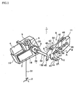
- FIG. 1 shows a range switching device of a vehicle (hereinafter referred to simply as “range switching device”) according to a first embodiment as an example of a range switching device according to the present invention.
- the figure is a perspective view that schematically shows the overall configuration of this range switching device 1.
- the range switching device 1 is incorporated in an automatic transmission (for example, multi-step automatic transmission or continuously variable transmission (CVT)) that is mounted in a vehicle.
- the main structural members of the range switching device 1 include a shift lever 2 which is a range selection unit which allows a vehicle driver to select a running range; a first control unit 3 for generating an electric signal (control signal) based on an electric signal (shift signal) S1 from the shift lever 2; a motor 4 which is controlled based on a control signal from the first control unit 3; a conversion mechanism 5 for converting rotary motion of the motor 4 to linear motion; an arm member 6 for converting the linear motion from the conversion mechanism 5 to a swinging motion; a spool 7 which is a range switching member moved by the arm member 6; a position sensor 8 which is a position detecting unit for detecting the position of the spool 7 through the arm member 6; and a detent mechanism 9 which positions and holds the spool 7.
- a shift lever 2 which is a range selection unit which allows
- the first control unit 3, the conversion mechanism 5, the arm member 6, and the position sensor 8 are accommodated in the same case member 10 and the motor 4 is mounted to this case member 10.
- the spool 7 is disposed within a valve body 11 of the automatic transmission.
- an intermediate member 150 which acts as a power transmission member, is disposed between the conversion mechanism 5 and the spool (range switching member) 7. As shown in the example of FIG. 1, this intermediate member 150 is provided with the arm member 6, a range control shaft 34, described later, and a detent lever 40, described later.
- Automatic transmission running ranges namely, parking (P), reverse (R), neutral (N) and drive (D), are indicated on the shift lever (range selection unit) 2.
- the shift lever 2 is operated directly by a vehicle driver, and any one of the above described running ranges can be selected. Then, a shift signal S1 corresponding to the selected running range is generated.
- Any range selection unit other than the shift lever 2 may be used so long as it can reflect the intention of the vehicle driver, that is, so long as the shift signal S1 corresponding to the running range selected by the vehicle driver can be generated.
- a shift button, a shift switch, a voice input device, or the like may be used.
- the first control unit 3 generates a control signal based on the shift signal S1 generated by the above described shift lever 2, and this control signal is used to control rotation of the motor 4. Further, a detection signal from the position sensor 8 for detecting the position of the spool 7 is inputted to the first control unit 3.
- the first control unit 3 controls a rotation direction of the motor 4 and a rotation start/stop timing based on this detection signal.
- the first control unit 3 is a control unit which switches the running range by controlling the operation of the spool 7 with the motor 4 based on the shift signal S1 from the shift lever 2, that is, a control unit (SBW-CU) for controlling a so-called shift-by-wire system (SBW).
- This first control unit 3 is disposed within the case member 10.
- the case member 10 includes a case main body 13 which is fixed on a part 12 (an A/T case) of the automatic transmission; an upper cover 14 that covers this case main body 13 from above; and an intermediate cover 15 that covers a section inside of the case main body 13.
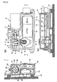
- FIG. 2(a) shows a state when the upper cover 14 and intermediate cover 15 are removed.
- FIGS. 2(b), (c) are sectional views of the case member 10 taken along the lines E-E and F-F, respectively, in FIG. 2(a).
- the above described first control unit 3 is installed on a rectangular base 17 provided on a bottom 16 of the case main body 13.
- a second control unit 18 that acts as an A/T ECU (automatic transmission electronic control unit) for controlling the entire automatic transmission is also installed on the base 17.
- the first and second control units 3 and 18 may be constructed on different substrate that are positioned in a row on the same base 17 as shown in FIG. 2(c), or may be constructed in different regions of the same substrate which is then disposed on the base 17. If both the control units 3 and 18 are constructed on the same substrate, a wire harness for inter-connection thereof can be omitted, and the number of steps required for assembling the range switching device 1 can be reduced.
- the motor 4 is installed to the outside of the case member 10 by insertion of an output shaft 20 thereof into the case member 10.
- a DC motor having a permanent magnet is used for the motor 4, and a rotation direction, rotation time and rotation timing thereof are controlled by the above described first control unit 3.
- the ball screw includes a ball screw shaft 21 which is driven by the motor 4; a ball nut (nut member) 22 which is engaged with the ball screw shaft 21 so as to be movable in the axial direction; and a plurality of balls 23 that are interposed between the ball screw shaft 21 and the ball nut 22.
- the ball nut 22 is engaged such that it is (a) incapable of rotating and (b) capable of axial direction movement with respect to the rotation of the ball screw shaft 21.
- balls 23 circulate within a tube 24 integrated with the ball nut 22, thus causing the ball nut 22 to move in the axial direction.
- the ball nut 22 is formed to be generally cylindrically and a guide groove 25 is formed along the axial direction on the rear side (the upper side in FIG. 3(a)) thereof.
- a guide rail 26 formed in parallel to the ball screw shaft 21 inside the case main body 13 is moveably fitted to this guide groove 25 as shown in FIGS. 2(a), (b). Consequently, rotation of the ball nut 22 is prevented.
- Grooves (engagement grooves) 27 and 28, which are perpendicular to the ball screw shaft 21, are formed in upper and lower sections of the ball nut 22. Part of the arm member 6, which will be described later, engages with these grooves 27 and 28.
- “Relatively ease” as used here means as easily as the ball screw shaft 21 is rotated by an operation of the detent mechanism 9, described later. Further, according to this embodiment, the conversion mechanism 5 is configured such that rotary motion is converted to linear motion, and conversely linear motion is converted to rotary motion. Note that, for example, increasing an angle of a screw groove of the ball screw shaft 21 allows linear motion of the ball nut 22 to be more easily converted to rotary motion of the ball screw shaft 21.
- the arm member 6 has a two-branch section 30 with a distal end that is divided into an upper section and a lower section. Cylindrical protrusions 30 and 31, which engage with the grooves 27 and 28 in the above described ball nut 22, are formed in the distal end of the two-branch section 30.
- a rectangular through hole 33 is made in a base end section of the arm member 6 as shown in FIG. 1.
- One end section of the range control shaft 34 which will be described later, is fitted into this through hole 33.
- the spool (range switching member) 7 constitutes part of a manual valve 35 disposed within the valve body 11.
- the spool 7 is supported so as to be freely movably in the axial direction (the directions of arrows A, B), and when the spool 7 is moved in the axial direction, a hydraulic path within the valve body 11 is changed so as to set a predetermined running range. That is, the spool 7 can be moved to the position P corresponding to the P range, a position R corresponding to the R range, a position N corresponding to the N range, and a position D corresponding to the D range.
- Two discs 36 and 36 are fixed to a distal end of the spool 7 and an engagement groove 37 is formed between these discs 36 and 36.
- the detent lever 40 described later, is engaged with this engagement groove 37.
- the position sensor 8 is disposed inside the intermediate cover 15 inside the case member 10.
- the range control shaft 34 goes through the center of this position sensor 8.
- a potentiometer may be used, which outputs a voltage corresponding to a rotation angle of the range control shaft 34.
- a rectangular prism shaped fitting section 38 is formed at an end section of the range control shaft 34 and this fitting section 38 is fitted into the rectangular through hole 33 in the above described arm member 6.
- the detent mechanism 9 includes the detent lever (detent member) 40, a detent spring 41 and a roller 42.
- the detent lever 40 is a plate-like member as shown in FIG. 1; a rectangular through hole 43 is formed in a lower section thereof, and a rectangular prism-shaped fitting section 44 formed at the other end of the range selection shaft 34 is fit into this through hole 43.
- the detent lever 40 swings in the directions of arrows C and D, with the range selection shaft 34 as a swing center.
- a through hole 45 which part of a parking mechanism (not shown) engages, is provided in a left lower section of the detent lever 4, as shown in FIG. 4.
- an arm section 46 is formed at a right lower section thereof as shown in FIG. 4, such that the arm section 46 points to the right, and a pin 47 is formed so as to protrude from the arm section 46.
- the detent lever 40 has four range grooves a, c, e and g formed in order (from the right of FIG. 1) in a top section thereof, as selection regions. Further, convex sections b, d and f are formed between each of these range grooves a, c, e and g.
- the range grooves a, c, e and g, described above, basically correspond to the four positions of the spool 7, namely, the positions P, R, N and D.
- range grooves a, c, e and g are regions having a given width (selection regions) and thus, strictly speaking, selection positions a1, c1, e1 and g1 in these range grooves a, c, e and g correspond to the positions P, R, N, D of the spool 7.
- selection positions a1, c1, e1 and g1 will be described following an explanation of the detent spring 41.
- the detent spring 41 is formed as a generally rectangular member and as shown in FIG. 1, is provided with a base end 48 which is fixed to the valve body 11a and a two-branch section 50 which is formed at a distal end thereof.
- a roller 42 is supported so as to be freely rotatably in the two-branch section 50.
- the detent spring 41 acts as a leaf spring, so that the roller 42 disposed rotatably at the distal end is pressed against the inclined faces of each of the range grooves a, c, e and g in the detent lever 40, thereby accurately positioning and holding the detent lever 40.
- the detent lever 40 is positioned in the selection position a1 by an urging force of the roller 42 resulting from elastic force of the detent spring 41.
- the selection position a1 is a point at which the range groove a makes contact with the roller 42 when the detent lever 40 is moved and then held by the urging force of the roller 42.
- the selection position c1 in the range groove c is a point at which the range groove c makes contact with the roller 42 when the detent lever 40 is moved and then held by the urging force of the roller 42.
- the selection position e1 set in a part of the range groove e and the selecting position g1 set in a part of the range groove g are set in the same way as the above described selection positions a1 and c1, and thus a description thereof is omitted.
- the selection positions a1, c1, e1 and g1 set in the above ways correspond exactly, in this order, to the positions P, R, N and D of the spool 7.
- Reference positions for rotating (swinging) in the directions of arrows C and D are set in the detent lever 40, and the relation between the angles from the reference position to the selection positions a1, c1, e1 and g1 and the convex sections b, d and f, and the magnitude of an output voltage from the position sensor 8 corresponding to each angle is memorized in the first control unit 3.
- the configuration is such that the swinging motion (rotary motion) of the detent lever 40 in the directions of arrows C and D and the moving motion of the spool 7 in the directions of arrows A and B are inter-linked, that is, the positions of the detent lever 40 corresponds in a one-to-one manner with the positions of the spool 7.
- the spool 7 is controlled accurately by accurately controlling the detent lever 40 without controlling the position of the spool 7 directly.
- the roller 42 of the detent mechanism 9 is positioned at the selection position a1 within the range groove a in FIG. 4. If the vehicle driver switches the shift lever 2 from the P range to the R range, a shift signal S 1 corresponding thereto is inputted to the first control unit 3.
- the motor 4 is rotated by the first control unit 3 so that the ball screw shaft 21 is rotated. Due to this rotation, the ball nut 22 is moved in the leftward direction of FIG. 2(a). Along with this, the arm member 6 swings in the leftward direction. Consequently, the detent lever 40 is rotated in the direction of arrow C by the range control shaft 34, so that the spool 7 is moved in the direction of arrow B.
- the first control unit 3 stops the rotation of the motor 4. As a result, the roller 42 moves from the range groove a, passes over the convex section b, and enters the range groove c.
- the detent lever 40 is rotated by the urging force of the roller 42 that is generated by the elastic force of the detent spring 41.
- the roller 42 is positioned and held accurately in the selection position c1 within the range groove c by this rotation. Consequently, the spool 7 that was located at the position P is accurately positioned at the position R. If the motor 4 is stopped and the detent lever 40 is rotated by the action of the detent mechanism 9, the ball nut 22 is moved in the axial direction by the range control shaft 34 and the arm member 6, so that the ball screw shaft 21 is rotated.
- the conversion mechanism 5 is configured from a ball screw and further, the conversion mechanism 5 also includes the arm member 6.
- the configuration necessary for deceleration is simplified, thereby reducing the overall size of the range switching device 1.
- the arm member 6 converts the linear motion in the axial direction of the ball nut 22 to the swinging motion, a large reduction ratio can be achieved. Further, the reduction ratio can be changed by changing the length of the arm member 6, which can be carried out simply.
- the first and second control units 3 and 18, which are electronic components, are disposed within the case member 10 together with the position sensor 8, which is also an electronic component, and are covered by the intermediate cover 15.
- the first and second control units 3 and 18 and the position sensor 8 are separated by the intermediate cover 15 from movable components such as the conversion mechanism 5, the arm member 6, and the like, which are disposed outside of the intermediate cover 15 but within the same case member 10.
- movable components such as the conversion mechanism 5, the arm member 6, and the like
- the length and quantity of the wire harnesses required for connecting these members can be minimized, thereby simplifying the wiring system. Consequently, reductions in component cost and assembly cost and space saving are achieved and further, the impact of electromagnetic noise caused by the wire harness being long can be reduced.
- FIGS. 5(a), (b), (c) show a range switching device 50 according to this embodiment. These figures correspond to FIGS. 2(a), (b), (c), in that order. Structural members that are the same as those shown in FIGS. 2(a), (b), (c) are denoted with the same reference numerals, and a description thereof is omitted.
- the first control unit 3 is positioned on the bottom section 16 of the case main body 13 of the case member 10 and the second control unit 18 is disposed on a supporting member 51 that is disposed above the first control unit 3.
- the first control unit 3 is positioned such that it is completely overlapped by the second control unit 18.
- the occupied area can be reduced by an amount equivalent to the overlapping area of the first and second control units 3 and 18.
- the first control unit 3 can be provided in addition to the second control unit 18 that is conventionally used, without the need for large changes in design and arrangement. As a result, a conventional range switching device can be used effectively.
- first and second control units 3 and 18 and the position sensor 8 are disposed inside the intermediate cover 15 in the same manner as the first embodiment.
- FIGS. 6(a), (b), (c) show a range switching device 60 according to this embodiment.
- spur gears 52a and 52b are interposed between the output shaft 20 of the motor 4 and the ball screw shaft 21 of the conversion mechanism 5.
- the spur gear 52a which has a small diameter, is fitted to the output shaft 20 of the motor 4, while the spur gear 52b, which has a large diameter, is fitted to the ball screw shaft 21.
- the spur gears 52a and 52b are meshed with each other.
- the gear ratio can be increased, whereby the size of the motor 4 can be reduced.
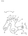
- a combination of a cam and a cam follower is used for the conversion mechanism 5 as shown in FIGS. 7(a), (b).
- the conversion mechanism 5 includes a shaft-shaped cam member 62 having a spiral cam groove 61; and two roller shaped cam followers 65 and 66 that are rotatably supported by a two-branch section 64 provided at a distal end of an arm member 63. These two cam followers 65 and 66 engage with the cam groove 61 of the cam member 62 at opposite sides to each other.
- the arm member 63 is supported by a shaft 67 such that it is capable of swinging.
- a configuration is provided having an extremely small friction coefficient, like the conversion mechanism 5 of the first to third embodiments that use a ball screw. Further, since structural members corresponding to the ball nut 22 and the balls 23 are unnecessary, as compared to the configuration of the first to third embodiments, the configuration can be simplified to this extent. The operation and effects are substantially the same as the first to third embodiments.
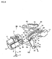
- FIG. 8 shows a range switching device 68 of the present invention. This embodiment illustrates an example of when the range switching device of the present invention is applied to a parking mechanism. Note that, structural members that are the same as those of the first embodiment are denoted with the same reference numerals, and a description thereof is omitted.
- the range switching member which is moved by the arm member 6 is the spool 7, which corresponds to the four positions, namely, positions P, R, N and D.
- the range switching device is a parking mechanism 73, which is constructed so as to correspond to two positions, namely, a position P (a lock position) and a non-P position (for example, a release position).
- the configuration of the detent lever 70 that constitutes the detent mechanism 9 is different to that of the detent lever 40 of the first embodiment.
- the detent spring 41 and the roller 42, which are other components of the detent mechanism 9, are the same as those of the first embodiment.
- a rectangular through hole 71 is formed in a lower section thereof.
- the rectangular prism fitting section 44 formed at the other end of the range control shaft 34 is fit into this through hole 71.
- a through hole 72 that a parking rod 74 of a parking mechanism 73, which will be described later, engages, is formed in a top section of the detent lever 70.
- Range grooves h and j are provided in the top edge of the detent lever 70 as two selection regions. Further, a convex section i is formed between these range grooves h and j.
- the above described range grooves h and j basically correspond to the lock position and the release position of the parking rod 74, which will be described later.
- range grooves h and j are regions (selection regions) having a given width, and that, speaking strictly, selection positions h1 and j1 (not shown) set in part of these range grooves h and j correspond to the lock position and the release position of the parking rod 74. Because the relationship of the range grooves h and j and the selection positions h1 and j1 is the same as the relationship of the range grooves a, c, e and g and the selection positions a1, c1, e1 and g1 of the first embodiment, a description thereof will be omitted.
- a reference position for when the detent lever 70 rotates (swings) in the directions of arrows C and D is set, and the relationship between the angle from this reference position to the selection positions h1 and j1 and the convex section I, and the magnitude of an output voltage from the position sensor 8 corresponding to each angle is memorized in the first control unit 3.
- the parking mechanism 73 includes a parking rod 74 having a proximal end that is bent in the shape of letter L and which engages the detent lever 70; a conical wedge 75 (lock member) which is fitted to a distal end of the parking rod 74 such that it is capable of moving; a spring (compression spring) 77 which is connected to a flange section 76 fixed on the parking rod 74 and the wedge 75; a support 78 disposed below the distal end of the parking rod 74; and a parking pole 80 which is capable of swing freely so that the wedge 75 is inserted into or removed from between the support 78 and the parking pole 80.
- the parking pole 80 is disposed such that it is capable of swinging freely in a substantially vertical direction with respect to an axis point 81 at the proximal end.
- a pawl 83 capable of engaging with and disengaging from a parking gear 82 fixed on an output shaft (not shown) of the automatic transmission is provided so as to protrude from the upper side of the parking pole 80.
- the detent lever 70 is rotated in the direction of arrow C by rotation of the motor 4 via the conversion mechanism 5, the arm member 6 and the range control shaft 34. Consequently, the parking rod 74 is moved in the direction of arrow G.
- the flange section 76 that is integrally formed with the parking rod 74 urges the wedge 75 in the direction of arrow G via the spring 77.
- the wedge 75 is inserted in between the support 78 and the parking pole 80, thereby pushing up the parking pole 80 such that the pawl 83 engages with the parking gear 82.
- the wedge 75 cannot be inserted between the support 78 and the parking pole 80, and thus the wedge 75 remains in a waiting position where it is urged by the spring 77. If the vehicle wheels move slightly in this condition, the parking gear 82 is rotated, and the pawl 83 enters into a tooth recess portion of the parking gear 82, thereby achieving parking lock.
- the shift lever 2 is used to select the non P range instead of the P range, whereby the detent lever 70 is rotated in the direction of arrow D by the motor 4, the conversion mechanism 5, the arm member 6, and the like. Consequently, the parking rod 34 is moved in the direction of arrow H, so that the wedge 75 is pulled out from between the support 78 and the parking pole 80. As a result, the parking pole 80 swings downward, such that the pawl 83 is pulled out of the tooth recess portion in the parking gear 82. With this, lock release is completed.
- a ball screw like that shown in FIG. 3, or a combination of the cam member 62 with the cam followers 65 and 66 shown in FIG. 7 may be used.
- the range switching device 68 of this embodiment when the parking rod 74 is moved from the release position to the position P in accordance with the vehicle driver switching the running range from the non P range to the P range, control of the motor 4 is executed until the convex section i of the detent lever 70 passes the roller 42 such that the roller 42 enters the range groove h. Following this, the roller 42 located in the range groove h is positioned and held at a selection position (not shown) due to the pulling action of the detent mechanism 9. Thus, the parking rod 74 can be accurately positioned at the position P, which corresponding to the P range which is the selected running range.
- the range switching device of the present invention is only used for switching between two positions, namely, the lock position (position P) and the release position (the non-P position).
- the parking mechanism 73 corresponds to the range switching device. It should be noted that, in this example, the selection of the running ranges N, D and R is carried out by another mechanism.
- FIG. 9 is a view of the case member 10, which includes the case main body 13, the intermediate cover 15 and the upper cover 14, as seen from the side of the upper cover 14 when the upper cover 14 is cut off;
- FIG. 10 is a view of the internal configuration as seen from the side of the upper cover 14 when the upper cover 14 and the intermediate cover 15 are removed;
- FIG. 11 is a perspective view taken along the line K-K of FIG. 9. Note that, FIG. 11 illustrates a state when the upper cover 14 is attached, rather than cut off as in FIG. 9.
- the case member 10 of the range switching device 100 shown in these figures includes the case main body 13 fixed on the A/T case 12, the upper cover 14 that covers this case main body 13 from above, and the intermediate cover 15 that covers a section inside of the case main body 13.
- the motor 4 is installed outside the case member 10 such that the output shaft 20 thereof is inserted into the case member 10.
- a small spur gear 52a is fixed on this output shaft 20 and a large spur gear 52b fixed on the ball screw shaft 21 is engaged with the spur gear 52a.
- respective forward and reverse rotations of the motor 4 are decelerated by these spur gears 52a and 52b and transmitted in the form of normal and reverse rotations, respectively, of the ball screw shaft 21.
- the ball nut 22 that meshes with the ball screw shaft 21 via the balls 23 (see FIG. 3) is moved in one or another direction along the length direction of the ball screw shaft 21 by the normal/reverse rotation of the ball screw shaft 21.
- the ball nut 22 is provided with a rotation stopper described hereinafter, which is different to that described previously.
- the grooves 27 and 28 are formed in the aforementioned ball nut 22 and the distal ends of an arm member 101 (which is different to that according to the above described embodiment and which will be described later) engage with these grooves 27 and 28.
- a range control shaft 102 (which is different to that according to the above described embodiment and which will be described later) is fitted to a proximal end of the arm member 101.
- a manual release mechanism 103 is provided to ensure switching of the running range even if a failure occurs in the motor or the like.
- first control unit 104 an SBW CU
- second control unit 105 an A/T ECU
- the range switching device 100 includes a manual release mechanism 103 as an auxiliary switching unit.
- the ball screw shaft 21 cannot be rotated if a trouble (failure) such as breakage or short-circuit occurs in the motor 4, which is the driving power source, whereby the running range cannot be switched.
- this embodiment includes the manual release mechanism 103 as shown in FIGS. 12(a), (b).
- the manual release mechanism 103 shown in these figures includes a release rod 106 which is disposed in parallel to the ball screw shaft 21 and which is supported by the case member 10 so as to be movably in the length direction; and a protrusion 107 which is formed so as to protrude from the ball nut 22.
- a hook (engagement section) 106a which is capable of engaging the protrusion 107 is provided at a distal end section of the release rod 106.
- a wire (not shown) capable of pulling the release rod 106 in the direction of arrow L is connected to a proximal end section 106b.
- the motor 4 fails to operate when the P range is selected, namely, when the state shown in FIG. 12(a) exists, the motor 4 is incapable of swinging the arm member 101 via the ball screw shaft 21 and the ball nut 22, and the like, and thus the running range cannot be changed over.
- the release rod 106 is moved in the direction of arrow L due to the aforementioned wire being pulled, and the ball nut 22 is moved in the direction of arrow L as a result of the hook 106a of the release rod 106 being hooked onto the protrusion 107 of the ball nut 22.
- the arm member 101 whose distal end section engages the ball nut 22 is swung and forcibly moved to a position that corresponds to the range N as shown in FIG. 12(b).
- the ball nut 22 is driven by the release rod 106.
- a release weight the force which pulls the wire
- a release stroke can be set appropriately depending on the length of the arm member 101, and a compact configuration can be provided.
- FIGS. 13(a), (b) show another example of a manual release mechanism.
- FIGS. 14(a), (b) illustrate the operation when this manual release mechanism 108 (auxiliary switching unit) is incorporated in the case member 10.
- the manual release mechanism 108 moves the arm member 101 directly instead of the ball nut 22.
- the manual release mechanism 108 includes a release rod 109 and a guide sleeve 110 that supports an intermediate section of the release rod 109 such that the release rod 109 is movably in the length direction.
- a hook (engagement section) 109a capable of engaging the intermediate section in the length direction of the arm member 101 is formed at a distal end section of the release rod 109.
- a convex section 109b which functions as a rotation stopped for the release rod 108, is provided so as to protrude at an intermediate section of the release rod 109 such that it is capable of movement along a groove 110a formed in the guide sleeve 110 having an open distal end.
- a wire similar to the one described previously (not shown), namely, a wire capable of pulling the release rod in the direction of arrow M, is connected to a proximal end section 109c of the release rod 109.
- the release rod 109 is moved in the direction of arrow M by the aforementioned wire being pulled, so that the hook 109a of the release rod 109 is hooked on the arm member 101, whereby the arm member 101 is swung. Consequently, the arm member 101 can be forcibly moved to the position indicated by the dotted line in FIGS. 13(a), (b) and the solid line in FIG. 14(b).
- the object driven by the release rod 109 is the arm member 101. Accordingly, the manual release mechanism 108 can be disposed freely regardless of the position of the ball nut.
- stopping of the rotation of the ball nut 22 is achieved by fitting the guide groove 28 formed in the ball nut 22 to the guide rail 26 such that it has a degree of play.
- a rotation stopping unit for the ball nut 22 is configured by: providing a bolt hole 110 in the case member 10, and fastening a bolt (pin-like member) 111 into this bolt hole 110, such that a distal end section 111a of the bolt 111 is fitted into the guide groove 25 in the bolt nut 22 with a degree of play.
- a seal ring 111b between the case member 10 and the bolt 111, the inside of the case member 10 is sealed.
- the configuration is simplified, whereby a reduction in the quantity of processing steps is possible.
- FIGS. 16(a), (b) show an other example of the ball nut rotation stopper (the rotation stopping unit).
- a rotation stopper for the ball nut 22 is configured by; providing a hole 10a in the case member 10, and inserting a long pin (engagement member) 112 that runs in parallel with the ball screw shaft 21 into this hole 10a such that the pin 112 is fitted with a degree of play into a guide groove 113 in the ball nut 22. Because this configuration is realized by simply inserting the pin 112 into the hole 10a, as compared to the above described configuration, the need for providing a bolt hole in the case member 10 is eliminated, whereby the special seal ring 111b (see FIG. 15(a)) becomes unnecessary.
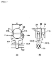
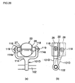
- FIGS. 17 to 20 show various shapes of arm members 101A to 101D.
- (a) of each figure indicates a section perpendicular to the axis of each ball nut 22.
- (b) of each figure, which is a view from the right side of (a) shows two respective outlines when the respective arm members 101A to 101D are positioned perpendicular to the ball nut 22, and when they are inclined at about 20° toward the right side.
- FIG. 19(c) illustrates the same state as (b).
- Each arm member 101A to 101D has a two-branch section 114. Fundamentally, among the structural members of these arm members 101A to 101D, only the portions that fit into the grooves 27, 28 (hereinafter referred to as "cam followers") are different in shape.
- a cam follower 115 is formed with a circular shape and distal ends 114a of the two-branch section 114 are tapered so as to connect to the bottom section (given the perspective of the figure) of this cam follower 115.
- a cam follower 116 has a circular shape and is formed by bending the distal ends 114a of the two-branch section 114 inwards to the ball nut 22 side, and inserting them into the grooves 27 and 28..
- the cam follower 17 is formed with a circular shape.
- the distal ends 114a of the two-branch section 114 overlap with the entire length of the cam follower 117 in the vertical direction of the figure.
- the cam follower 117 may be configured such that the distal end 114a of the two-branch section 114 are welded as shown in FIG. 19(b), or may be formed integrally with the distal ends 114a of the two-branch section 114.
- the cam follower 118 in FIG. 20 is formed by a roller-like member. This cam follower 118 is rotatably supported by a shaft 119 that is supported by the distal ends 114a of the two-branch section 114.
- the cam follower 118 shown in FIG. 20 enables the arm member 101D to swing with a smooth motion along with movement of the ball nut 22.
- each arm member 101A to 101D is symmetrical with respect to the vertical center line in the figures, as shown in (a) of each of FIGS. 17 to 20, the arm members 101A to 101D can be constructed by joining together two components of the same shape that are separated into left-right sections with respect to this center line. In this case, production costs can be reduced through mass production of components having the same shape.
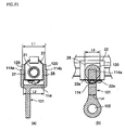
- the arm member 101 may be constructed with the configuration shown in FIG. 21.
- FIG. 21(a) shows a section in a direction perpendicular to the axis of the ball nut 22.
- FIG. 21(b) is a view of (a) as seen from the right side.
- a width L3 of the groove 28 (27) in the ball nut 22 is enlarged, and correspondingly the outside diameter of the circular cam follower 120 is enlarged.
- a width L4 of the distal end 114a of the two-branch section 114 is shortened. Consequently, for example, even if the arm member 101 is inclined to the left side or right side from the state shown in FIG. 2 1 (b), interference between the side wall 22a of the groove 28 (27) and the distal end 114a of the two-branch section 114 can be effectively prevented.
- the distance L2 between the distal ends 114a can be made smaller than the outside diameter L1 (see FIG. 17(a)) of the ball nut 22, as shown in FIG. 21(a). That is, it is possible to reduce the space occupied since it is possible to make the configuration of the two-branch section smaller.
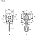
- FIGS. 22(a), (b) show still an other example of the arm member.
- the width L3 of the groove 28 (27) in the ball nut 22 is formed to be large, and correspondingly the outside diameter of the circular cam follower 120 is enlarged. Further, the width L4 between the distal ends 114a of the two-branch section 114 is reduced. As a result, even if the arm member 101 is inclined to the right side or left side from the state shown in FIG. 22 (b), interference between the side wall 22a of the groove 28 (27) and the distal end 114a of the two-branch section 114 can be effectively blocked. Consequently, as shown in FIG.
- the width (distance) L2 between the distal ends 114a can be made smaller than a width L5 of the ball nut 22. That is, it is possible to make the configuration of the two-branch section 114 small, whereby it is possible to reduce the occupied space. Because the configuration of the arm member 101 shown in FIGS. 22(a), (b) is symmetrical with respect to the center line in the vertical direction in (a), like those shown in FIGS. 17 to 20 above, the arm member 101 can be constructed by joining together two components of the same shape that are separated into left-right sections with respect to this center line. Consequently, production costs can be reduced through mass production of components having the same shape.
- FIGS. 11 and 23 are semi-exploded perspective views of the range switching device 100, showing the range control shaft 102 of this embodiment.
- the range control shaft 102 includes a distal end supporting section 121, an arm fitting section (rectangular prism section) 122, a sensor fitting section 123, a rear end supporting section 124 and a lever fitting section 125, in that order from the distal end side (the upper section in FIG. 11) to the proximal end side.
- the distal end supporting section 121 is formed to be cylindrically, and fits into a cylindrical concave section 14a in the upper cover 14 of the case member 10. That is, the distal end supporting section 121 has a spigot-joint like configuration and is supported rotatably by the concave section 14a.
- the arm fitting section 122 is formed as a square pipe, and fits into the rectangular through hole (fitting section) 126 made in the arm member 101.
- the sensor fitting section 123 has a step and passes through the center of the position sensor 8 and is fitted in the through hole provided in the position sensor 8.
- the rear end supporting section 124 is formed so as to be cylindrically, and is rotatably supported by a needle bearing (bearing member) 127 attached to a part (the case 12) of the automatic transmission.
- the lever fitting section 125 is formed as a square pipe, and fits into the rectangular through hole 43 in the detent lever 40.
- the range control shaft 102 is supported at by both ends in the length direction, namely, the distal end supporting section 121 and the rear end supporting section 124 are supported rotatably by the concave section 14a and the needle bearing 127, the influence of angle error on the position sensor 8 can be reduced.
- the spigot-joint like configuration for the fitting configuration namely a fitting configuration 128, in which the case member 10 of the SBW unit is fit to the A/T case 12, this non-required inclination can be inhibited.
- the A/T case 12 and the SBW unit is accurately connected and at the same time, the distal end supporting section 121 of the range control shaft 102 is fitted into the concave section 14a. Consequently, the range control shaft 102 is rotatably supported by the distal end supporting section 121 and the rear end supporting section 124, thereby inhibiting occurrence of non-required inclination of the range control shaft 102.
- the range switching device can be installed onto the casing as a single unit together with the case member 10. Therefore, this range switching device can be easily installed on a vehicle that is not provided with the range switching device of the present invention.
- power train refers to: an engine as a drive unit; an automatic transmission (A/T) that automatically executes a take-off operation and speed change operation; a semi-automatic transmission in which speed change is carried out manually; a continuous variable transmission (CVT) capable of controlling a speed change ratio of a shifted gear; an internal combustion engine and an electric motor for driving a hybrid vehicle; or a motor for driving an electric motor.
- A/T automatic transmission
- CVT continuous variable transmission
- the first control unit 104 for controlling the motor 4 and the second control unit 105 for controlling the automatic transmission are separate. That is, the first control unit 104 for controlling the motor 4 is provided on a separate substrate from the second control unit 105. Further, the first control unit 104 and the second control unit 105 are housed in independent concave housing chambers 130 and 131, which have different sizes. These housing chambers 130 and 131 are divided by a wall section 132. Thus, the second control unit 105 can use the same case, even when the final product does not employ the first control unit 104.
- first control unit 104 and the second control unit 105 are housed in the accommodating chambers 130 and 131 having different sizes, they can be easily positioned at the time of installation and their positioning accuracies can be improved. Moreover, in the case of bonding the first and second control units 104 and 105 with adhesive agent, even if excessive adhesive agent is applied, there is no possibility that that the adhesive agent will flow out into the other accommodating chamber, thereby impairing the control unit therein.
- the accommodating chambers 104 and 105 are configured such that they communicate with each other by providing a gap in the top section of the wall section, the number of breathers can be reduced to one, as compared to a case when two breathers are needed due to the first and second control units 104 and 105 being accommodated in separate accommodating chambers.
- FIG. 24 is a perspective view that schematically shows the configuration of a range switching device 140 of this embodiment.
- an intermediate member 150 is disposed between the conversion mechanism 5 and the range switching member 7.
- the intermediate member 150 includes the range control shaft 102 which is freely rotatable, the detent lever 40 installed on the top of the range control shaft 102, and an arm member 101E installed on the bottom of the range control shaft 102.
- the range control shaft 102, the detent lever 40 and the arm member 101E rotate (swing) in an integrated manner around the range control shaft 102.
- the detent lever 40 has a plurality of range grooves a, c, e and g.
- the range switching member 7 is positioned at a predetermined corresponding position via the intermediate member 150.
- the arm member 101E shown in the figure has three arms 101a, 101b and 101c. These three arms 101a, 101b and 101c are disposed at positions that are substantially 120 degrees apart in the circumferential direction. Of these arms, the arm 101a is engaged with the ball nut 22 that constitutes, along with the ball screw shaft 21, a ball screw (which act as the conversion mechanism 5).
- the arm 101b is connected to the range switching member 7 through the connecting member 7a.
- the arm 101c is connected to the parking rod 74 of the parking mechanism 73. Referring to the figure, the range switching member 7 is disposed at the P range (parking) and then, the parking rod 74 is moved in the direction of the arrow.
- the compression spring 77 is urged in the direction of the arrow by the flange section 76 that is integrated with the parking rod 74, and the wedge 75 is urged in the direction of the arrow by this compression spring 77, so that the parking pole 80 is urged upward.
- the pawl 83 of the parking pawl 80 engages the parking gear 82 so that locking takes place.
- the ball screw shaft 21 for moving the ball nut 22, the range switching member 7 and the parking rod 74 are disposed such that their axes are located on substantially the same plane. Consequently, when the arm member 101E swings, only a rotation force around the range control shaft 102 is applied, and no other unnecessary rotation force is generated. Further, the ball screw shaft 21 and the parking rod 74 are disposed substantially in parallel to each other and the movement direction of the ball nut 22 is opposite to the movement direction of the parking rod 74. Additionally, the range switching member 7 is disposed perpendicular to the ball screw shaft 21 and the parking rod 74, so that it moves in the perpendicular direction.
- the range switching member 7 and the parking rod 74 are disposed with the above described positional relationship and movement directions with respect to the arm member 101E, the range switching member 7 and the parking rod 74 can operate smoothly with a linear motion along the length direction, as a result of the swinging motion of the arm member 101E originating from the linear motion of the ball nut 22. Further, the movement direction of the range switching member 7 is different from the movement direction of the parking rod 74, so that when the range switching member 7 is moved, it is unlikely to be affected by the movement of the parking rod 74. Therefore, movement accuracy and positioning accuracy of the range switching member 7 can be improved.
- the invention is not limited to the above description, and by interposing the arm member 101E in the above described manner, the movement directions of the parking rod 74 and the range switching member 7 may be set as chosen. In other words, it is possible to set the positional relationship and the movement direction of these members as chosen, thus allowing design freedom to be substantially improved. It should be noted that, if necessary for reasons related to space constraints, the ball screw shaft 21, the range switching member 7 and the parking rod 74 do not need to be disposed on the same plane.
Landscapes
- Engineering & Computer Science (AREA)
- General Engineering & Computer Science (AREA)
- Mechanical Engineering (AREA)
- Food Science & Technology (AREA)
- Gear-Shifting Mechanisms (AREA)
- Transmission Devices (AREA)
- Arrangement And Mounting Of Devices That Control Transmission Of Motive Force (AREA)
Applications Claiming Priority (6)
| Application Number | Priority Date | Filing Date | Title |
|---|---|---|---|
| JP2003114970 | 2003-04-18 | ||
| JP2003114970 | 2003-04-18 | ||
| JP2003431612 | 2003-12-25 | ||
| JP2003431612 | 2003-12-25 | ||
| JP2004061443 | 2004-03-04 | ||
| JP2004061443A JP2005207570A (ja) | 2003-04-18 | 2004-03-04 | 車輌のレンジ切換え装置 |
Publications (2)
| Publication Number | Publication Date |
|---|---|
| EP1469236A2 true EP1469236A2 (de) | 2004-10-20 |
| EP1469236A3 EP1469236A3 (de) | 2009-12-23 |
Family
ID=32912849
Family Applications (1)
| Application Number | Title | Priority Date | Filing Date |
|---|---|---|---|
| EP04009237A Withdrawn EP1469236A3 (de) | 2003-04-18 | 2004-04-19 | Vorrichtung zur Auswahl einer Fahrstufe eines Fahrzeugs |
Country Status (5)
| Country | Link |
|---|---|
| US (1) | US7146871B2 (de) |
| EP (1) | EP1469236A3 (de) |
| JP (1) | JP2005207570A (de) |
| KR (1) | KR20040090701A (de) |
| CN (1) | CN1537744A (de) |
Cited By (19)
| Publication number | Priority date | Publication date | Assignee | Title |
|---|---|---|---|---|
| EP1826463A1 (de) * | 2006-02-24 | 2007-08-29 | Yamaha Hatsudoki Kabushiki Kaisha | Schaltvorrichtung, Fahrzeug, und Herstellungsverfahren für ein Fahrzeug |
| US7367923B2 (en) | 2004-12-10 | 2008-05-06 | Yamaha Hatsudoki Kabushiki Kaisha | Apparatus and method for controlling transmission of straddle-type vehicle |
| US7497804B2 (en) | 2006-04-18 | 2009-03-03 | Yamaha Hatsudoki Kabushiki Kaisha | Automatic gearshift control device and vehicle |
| US7510503B2 (en) | 2006-02-24 | 2009-03-31 | Yamaha Hatsudoki Kabushiki Kaisha | Clutch failure detector, automatic clutch system and straddle-type vehicle |
| US7513849B2 (en) | 2006-04-18 | 2009-04-07 | Yamaha Hatsudoki Kabushiki Kaisha | Automated transmission controller and vehicle including the automated transmission controller |
| US7635054B2 (en) | 2006-04-18 | 2009-12-22 | Yamaha Hatsudoki Kabushiki Kaisha Kabushiki Kaisha Moric | Clutch actuator, engine unit, and saddle type vehicle |
| US7654374B2 (en) | 2006-04-18 | 2010-02-02 | Yamaha Hatsudoki Kabushiki Kaisha | Automated transmission controller and vehicle including the automated transmission controller |
| US7665567B2 (en) | 2006-04-18 | 2010-02-23 | Yamaha Hatsudoki Kabushiki Kaisha | Shift actuator, vehicle, and method of integrating vehicle |
| US7673727B2 (en) | 2006-04-18 | 2010-03-09 | Yamaha Hatsudoki Kabushiki Kaisha | Automatic shift control device and vehicle |
| US7699151B2 (en) | 2006-04-18 | 2010-04-20 | Yamaha Hatsudoki Kabushiki Kaisha | Clutch actuator, engine unit, and saddle type vehicle |
| US7721624B2 (en) | 2005-09-30 | 2010-05-25 | Aisin Aw Co., Ltd. | Automatic transmission and running range switching device |
| US7721858B2 (en) | 2006-04-18 | 2010-05-25 | Yamaha Hatsudoki Kabushiki Kaisha | Clutch actuator, engine unit, and saddle type vehicle |
| US7823472B2 (en) | 2004-07-01 | 2010-11-02 | Yamaha Hatsudoki Kabushiki Kaisha | Shift control device for vehicle, and vehicle including the shift control device |
| US7881847B2 (en) | 2006-04-18 | 2011-02-01 | Yamaha Hatsudoki Kabushiki Kaisha | Clutch control device and vehicle |
| WO2011023544A1 (de) * | 2009-08-25 | 2011-03-03 | Zf Friedrichshafen Ag | Elektrisch betreibbare parksperrenvorrichtung für ein fahrzeuggetriebe |
| US7912613B2 (en) | 2004-07-01 | 2011-03-22 | Yamaha Hatsudoki Kabushiki Kaisha | Riding type vehicle |
| US8403093B2 (en) | 2004-07-26 | 2013-03-26 | Yamaha Hatsudoki Kabushiki Kaisha | Speed change controller for saddle-ride type vehicles |
| EP3022469A2 (de) * | 2013-07-18 | 2016-05-25 | Fca Us Llc | Verfahren für robuste parksperrsteuerung |
| DE102014116581B4 (de) | 2013-11-26 | 2021-07-29 | GM Global Technology Operations, LLC (n.d. Ges. d. Staates Delaware) | Mechanismus zum rückführen eines fahrzeuggetriebes in eine park-stellung und fahrzeug mit einem solchen mechanismus |
Families Citing this family (30)
| Publication number | Priority date | Publication date | Assignee | Title |
|---|---|---|---|---|
| JP4840092B2 (ja) * | 2006-11-13 | 2011-12-21 | アイシン・エィ・ダブリュ株式会社 | シフトバイワイヤ式レンジ切換え装置 |
| US7926374B2 (en) * | 2007-03-08 | 2011-04-19 | Dura Global Technologies, Llc | Voice recognition shift control |
| US7574938B2 (en) * | 2007-04-10 | 2009-08-18 | Gm Global Technology Operations, Inc. | Backup alignment system for an internal mode switch |
| CN101680538A (zh) * | 2007-09-28 | 2010-03-24 | 爱信艾达株式会社 | 自动变速器控制单元 |
| WO2009041678A1 (ja) * | 2007-09-28 | 2009-04-02 | Aisin Aw Co., Ltd. | 自動変速機の制御ユニット |
| CN101408245B (zh) * | 2007-10-10 | 2012-10-03 | 光阳工业股份有限公司 | 车辆排挡机构 |
| ATE519048T1 (de) * | 2008-01-14 | 2011-08-15 | Sila Holding Ind Spa | Steuereinrichtung für ein getriebe, insbesondere für ein kraftfahrzeuggetriebe, mit einem system zur erkennung des eingelegten getriebeganges |
| US20090199672A1 (en) * | 2008-02-07 | 2009-08-13 | John Impellizeri | Universal Selector Shaft for Motor Vehicle Transmissions |
| WO2009119115A1 (en) * | 2008-03-28 | 2009-10-01 | Aisin Aw Co., Ltd. | Vehicle range change apparatus |
| CN101654099B (zh) * | 2008-08-23 | 2012-05-23 | 比亚迪股份有限公司 | 一种汽车驻车机构及包括该机构的变速器 |
| JP5331514B2 (ja) * | 2009-02-26 | 2013-10-30 | 本田技研工業株式会社 | 鞍乗り型車両の変速制御装置 |
| JP2010223355A (ja) * | 2009-03-24 | 2010-10-07 | Aisin Aw Co Ltd | シフトバイワイヤ装置 |
| KR101070320B1 (ko) * | 2009-10-07 | 2011-10-06 | 김원태 | 원호운동 변환 장치 및 그 방법 |
| ITMO20100303A1 (it) * | 2010-10-29 | 2012-04-30 | Cnh Italia Spa | Dispositivo di controllo per un veicolo a cingoli. |
| DE102012007061B4 (de) * | 2012-04-02 | 2015-12-31 | Getrag Getriebe- Und Zahnradfabrik Hermann Hagenmeyer Gmbh & Cie Kg | Parksperrenanordnung und Kraftfahrzeuggetriebe |
| DE102013209085B4 (de) * | 2012-05-29 | 2021-05-12 | GM Global Technology Operations, LLC (n.d. Ges. d. Staates Delaware) | Hydraulisches steuerungssystem für ein automatikgetriebe mit einer analogen elektronischen getriebestufenauswahl |
| US8894545B2 (en) * | 2012-05-29 | 2014-11-25 | Gm Global Technology Operations, Llc | Hydraulic control system for an automatic transmission having analog electronic transmission range selection |
| JP5983040B2 (ja) * | 2012-05-30 | 2016-08-31 | 日本精工株式会社 | アクチュエータ |
| JP6047371B2 (ja) * | 2012-10-31 | 2016-12-21 | 株式会社ハイレックスコーポレーション | 開閉駆動装置 |
| JP6084006B2 (ja) * | 2012-11-01 | 2017-02-22 | 三輪精機株式会社 | 変速機操作装置 |
| CN104048026B (zh) * | 2013-03-14 | 2016-09-21 | 本田技研工业株式会社 | 变速器 |
| CN203442082U (zh) * | 2013-09-10 | 2014-02-19 | 大陆汽车电子(芜湖)有限公司 | 凸轮齿轮和包括该凸轮齿轮的直线驱动装置 |
| JP5762582B1 (ja) * | 2014-02-04 | 2015-08-12 | 三菱電機株式会社 | シフトレンジ切り替え装置 |
| CN104776213B (zh) * | 2015-04-09 | 2017-03-15 | 中国北方车辆研究所 | 一种装甲车辆自动换档装置 |
| JP6686966B2 (ja) * | 2017-05-17 | 2020-04-22 | 株式会社デンソー | 回転式アクチュエータ |
| KR20200058151A (ko) * | 2018-11-19 | 2020-05-27 | 현대자동차주식회사 | 전기 자동차의 다단 변속기용 기어 시프팅 장치 |
| US11085534B2 (en) * | 2018-11-21 | 2021-08-10 | Hyundai Motor Company | Gear shifting apparatus for multi-speed transmission for electric vehicles |
| JP7071314B2 (ja) * | 2019-07-12 | 2022-05-18 | 本田技研工業株式会社 | 鞍乗り型車両の変速装置 |
| DE102021200929A1 (de) | 2020-02-04 | 2021-08-05 | Dana Heavy Vehicle Systems Group, Llc | Verfahren und systeme für ein stellantriebssystem |
| DE102021100602A1 (de) | 2021-01-14 | 2022-07-14 | Bayerische Motoren Werke Aktiengesellschaft | Parksperrenmechanismus für ein Kraftfahrzeug |
Citations (3)
| Publication number | Priority date | Publication date | Assignee | Title |
|---|---|---|---|---|
| US4843901A (en) | 1987-09-14 | 1989-07-04 | Peterson David C | Electric shift apparatus with manual override |
| JPH07310820A (ja) | 1994-05-19 | 1995-11-28 | Tokai Rika Co Ltd | 車両用オートマチックトランスミッションの操作装置 |
| JP2002310295A (ja) | 2001-04-09 | 2002-10-23 | Koyo Seiko Co Ltd | 車両用自動変速機の操作装置 |
Family Cites Families (10)
| Publication number | Priority date | Publication date | Assignee | Title |
|---|---|---|---|---|
| GB714709A (en) * | 1950-10-30 | 1954-09-01 | Cleveland Pneumatic Tool Co | Improvements in or relating to gear shift controlling apparatus |
| US4790204A (en) * | 1987-07-16 | 1988-12-13 | Automotive Products, Plc | Electric shift apparatus |
| JP2508728Y2 (ja) * | 1990-02-28 | 1996-08-28 | アイシン精機株式会社 | 自動変速機のレンジ切替え装置 |
| JPH11218218A (ja) * | 1998-01-30 | 1999-08-10 | Mitsubishi Electric Corp | 自動変速装置の変速制御弁操作用アクチュエータ |
| US6016717A (en) * | 1998-05-18 | 2000-01-25 | Teleflex Incorporated | Helical cable actuator for shift by wire system |
| US6487484B1 (en) * | 1999-03-05 | 2002-11-26 | Shobers, Inc. | Shifting apparatus for an automatic transmission that is adapted to provide installation flexibility where space is limited within a motor vehicle |
| JP2001182828A (ja) * | 1999-12-27 | 2001-07-06 | Aisin Aw Co Ltd | 自動変速機のレンジ切り替え装置 |
| DE10038524A1 (de) * | 2000-05-15 | 2001-11-22 | Daimler Chrysler Ag | Automatisches Getriebe |
| DE10054977C2 (de) * | 2000-11-06 | 2002-10-24 | Siemens Ag | Stellvorrichtung für ein einstellbares Getriebe |
| US6612202B2 (en) * | 2000-12-15 | 2003-09-02 | Siemens Vdo Automotive Corporation | Mechatronics sensor |
-
2004
- 2004-03-04 JP JP2004061443A patent/JP2005207570A/ja not_active Withdrawn
- 2004-04-03 KR KR1020040023192A patent/KR20040090701A/ko not_active Application Discontinuation
- 2004-04-16 US US10/825,595 patent/US7146871B2/en active Active
- 2004-04-19 EP EP04009237A patent/EP1469236A3/de not_active Withdrawn
- 2004-04-19 CN CNA2004100329570A patent/CN1537744A/zh active Pending
Patent Citations (3)
| Publication number | Priority date | Publication date | Assignee | Title |
|---|---|---|---|---|
| US4843901A (en) | 1987-09-14 | 1989-07-04 | Peterson David C | Electric shift apparatus with manual override |
| JPH07310820A (ja) | 1994-05-19 | 1995-11-28 | Tokai Rika Co Ltd | 車両用オートマチックトランスミッションの操作装置 |
| JP2002310295A (ja) | 2001-04-09 | 2002-10-23 | Koyo Seiko Co Ltd | 車両用自動変速機の操作装置 |
Cited By (21)
| Publication number | Priority date | Publication date | Assignee | Title |
|---|---|---|---|---|
| US8001864B2 (en) | 2004-07-01 | 2011-08-23 | Yamaha Hatsudoki Kabushiki Kaisha | Actuation force transmission mechanism and straddle-type vehicle |
| US7912613B2 (en) | 2004-07-01 | 2011-03-22 | Yamaha Hatsudoki Kabushiki Kaisha | Riding type vehicle |
| US7823472B2 (en) | 2004-07-01 | 2010-11-02 | Yamaha Hatsudoki Kabushiki Kaisha | Shift control device for vehicle, and vehicle including the shift control device |
| US8403093B2 (en) | 2004-07-26 | 2013-03-26 | Yamaha Hatsudoki Kabushiki Kaisha | Speed change controller for saddle-ride type vehicles |
| US7367923B2 (en) | 2004-12-10 | 2008-05-06 | Yamaha Hatsudoki Kabushiki Kaisha | Apparatus and method for controlling transmission of straddle-type vehicle |
| US7721624B2 (en) | 2005-09-30 | 2010-05-25 | Aisin Aw Co., Ltd. | Automatic transmission and running range switching device |
| EP1826463A1 (de) * | 2006-02-24 | 2007-08-29 | Yamaha Hatsudoki Kabushiki Kaisha | Schaltvorrichtung, Fahrzeug, und Herstellungsverfahren für ein Fahrzeug |
| US7510503B2 (en) | 2006-02-24 | 2009-03-31 | Yamaha Hatsudoki Kabushiki Kaisha | Clutch failure detector, automatic clutch system and straddle-type vehicle |
| US7699151B2 (en) | 2006-04-18 | 2010-04-20 | Yamaha Hatsudoki Kabushiki Kaisha | Clutch actuator, engine unit, and saddle type vehicle |
| US7673728B2 (en) | 2006-04-18 | 2010-03-09 | Yamaha Hatsudoki Kabushiki Kaisha | Automated transmission controller and vehicle including the automated transmission controller |
| US7673727B2 (en) | 2006-04-18 | 2010-03-09 | Yamaha Hatsudoki Kabushiki Kaisha | Automatic shift control device and vehicle |
| US7665567B2 (en) | 2006-04-18 | 2010-02-23 | Yamaha Hatsudoki Kabushiki Kaisha | Shift actuator, vehicle, and method of integrating vehicle |
| US7721858B2 (en) | 2006-04-18 | 2010-05-25 | Yamaha Hatsudoki Kabushiki Kaisha | Clutch actuator, engine unit, and saddle type vehicle |
| US7654374B2 (en) | 2006-04-18 | 2010-02-02 | Yamaha Hatsudoki Kabushiki Kaisha | Automated transmission controller and vehicle including the automated transmission controller |
| US7881847B2 (en) | 2006-04-18 | 2011-02-01 | Yamaha Hatsudoki Kabushiki Kaisha | Clutch control device and vehicle |
| US7635054B2 (en) | 2006-04-18 | 2009-12-22 | Yamaha Hatsudoki Kabushiki Kaisha Kabushiki Kaisha Moric | Clutch actuator, engine unit, and saddle type vehicle |
| US7513849B2 (en) | 2006-04-18 | 2009-04-07 | Yamaha Hatsudoki Kabushiki Kaisha | Automated transmission controller and vehicle including the automated transmission controller |
| US7497804B2 (en) | 2006-04-18 | 2009-03-03 | Yamaha Hatsudoki Kabushiki Kaisha | Automatic gearshift control device and vehicle |
| WO2011023544A1 (de) * | 2009-08-25 | 2011-03-03 | Zf Friedrichshafen Ag | Elektrisch betreibbare parksperrenvorrichtung für ein fahrzeuggetriebe |
| EP3022469A2 (de) * | 2013-07-18 | 2016-05-25 | Fca Us Llc | Verfahren für robuste parksperrsteuerung |
| DE102014116581B4 (de) | 2013-11-26 | 2021-07-29 | GM Global Technology Operations, LLC (n.d. Ges. d. Staates Delaware) | Mechanismus zum rückführen eines fahrzeuggetriebes in eine park-stellung und fahrzeug mit einem solchen mechanismus |
Also Published As
| Publication number | Publication date |
|---|---|
| US20040261559A1 (en) | 2004-12-30 |
| EP1469236A3 (de) | 2009-12-23 |
| JP2005207570A (ja) | 2005-08-04 |
| CN1537744A (zh) | 2004-10-20 |
| US7146871B2 (en) | 2006-12-12 |
| KR20040090701A (ko) | 2004-10-26 |
Similar Documents
| Publication | Publication Date | Title |
|---|---|---|
| EP1469236A2 (de) | Vorrichtung zur Auswahl einer Fahrstufe eines Fahrzeugs | |
| US10281038B2 (en) | Actuator for shift by wire automatic transmission | |
| KR100743131B1 (ko) | 레인지절환장치 | |
| US8176807B2 (en) | Control unit for automatic transmission | |
| EP1156240B1 (de) | Elektrische betätigung zur getriebeschaltung | |
| US7721624B2 (en) | Automatic transmission and running range switching device | |
| KR100851373B1 (ko) | 수동 변속기용 자동 변속 조작 장치 | |
| KR100488706B1 (ko) | 수동 변속기의 변속 조작장치 | |
| US20090241715A1 (en) | Range shifting apparatus | |
| JP5254345B2 (ja) | 車輌のレンジ切換え装置 | |
| JP4753268B2 (ja) | 車輌のレンジ切替え装置 | |
| JP2006519958A (ja) | 手動変速機装着用自動変速装置 | |
| KR100585997B1 (ko) | 차량용 미러 조정기구의 클러치 구조 | |
| JP2002317871A (ja) | 変速機用電動駆動装置 | |
| JPH10278758A (ja) | パーキング機構 | |
| JP4344268B2 (ja) | 車両用自動変速機のディテント構造 | |
| CN214661967U (zh) | 变速器用的锁止板、车辆用的变速器及车辆 | |
| JPH0323406Y2 (de) | ||
| JP2007100765A (ja) | 車輌のレンジ切換え装置 | |
| JP2008223813A (ja) | シフトバイワイヤ式自動変速機 | |
| KR20230162603A (ko) | 시프트-바이-와이어 기구를 위한 기어 선택 작동기 | |
| JP2003254433A (ja) | 車輌のレンジ切替え装置 | |
| JP2006064163A (ja) | 自動変速機のセレクトアシスト装置 | |
| JP2008144790A (ja) | 自動変速機のレンジ切換制御装置 | |
| JP2007203755A (ja) | シフトレバー装置 |
Legal Events
| Date | Code | Title | Description |
|---|---|---|---|
| PUAI | Public reference made under article 153(3) epc to a published international application that has entered the european phase |
Free format text: ORIGINAL CODE: 0009012 |
|
| AK | Designated contracting states |
Kind code of ref document: A2 Designated state(s): AT BE BG CH CY CZ DE DK EE ES FI FR GB GR HU IE IT LI LU MC NL PL PT RO SE SI SK TR |
|
| AX | Request for extension of the european patent |
Extension state: AL HR LT LV MK |
|
| PUAL | Search report despatched |
Free format text: ORIGINAL CODE: 0009013 |
|
| AK | Designated contracting states |
Kind code of ref document: A3 Designated state(s): AT BE BG CH CY CZ DE DK EE ES FI FR GB GR HU IE IT LI LU MC NL PL PT RO SE SI SK TR |
|
| AX | Request for extension of the european patent |
Extension state: AL HR LT LV MK |
|
| AKX | Designation fees paid |
Designated state(s): DE FR GB |
|
| STAA | Information on the status of an ep patent application or granted ep patent |
Free format text: STATUS: THE APPLICATION IS DEEMED TO BE WITHDRAWN |
|
| 18D | Application deemed to be withdrawn |
Effective date: 20100624 |