EP1469139B1 - Profilanschlussleiste für einen Übergang von einem Bauteil zu einer Gebäudewand - Google Patents
Profilanschlussleiste für einen Übergang von einem Bauteil zu einer Gebäudewand Download PDFInfo
- Publication number
- EP1469139B1 EP1469139B1 EP04008917.9A EP04008917A EP1469139B1 EP 1469139 B1 EP1469139 B1 EP 1469139B1 EP 04008917 A EP04008917 A EP 04008917A EP 1469139 B1 EP1469139 B1 EP 1469139B1
- Authority
- EP
- European Patent Office
- Prior art keywords
- molding
- foam tape
- foam
- tape
- component
- Prior art date
- Legal status (The legal status is an assumption and is not a legal conclusion. Google has not performed a legal analysis and makes no representation as to the accuracy of the status listed.)
- Revoked
Links
Images


Classifications
-
- E—FIXED CONSTRUCTIONS
- E06—DOORS, WINDOWS, SHUTTERS, OR ROLLER BLINDS IN GENERAL; LADDERS
- E06B—FIXED OR MOVABLE CLOSURES FOR OPENINGS IN BUILDINGS, VEHICLES, FENCES OR LIKE ENCLOSURES IN GENERAL, e.g. DOORS, WINDOWS, BLINDS, GATES
- E06B1/00—Border constructions of openings in walls, floors, or ceilings; Frames to be rigidly mounted in such openings
- E06B1/62—Tightening or covering joints between the border of openings and the frame or between contiguous frames
-
- E—FIXED CONSTRUCTIONS
- E04—BUILDING
- E04F—FINISHING WORK ON BUILDINGS, e.g. STAIRS, FLOORS
- E04F13/00—Coverings or linings, e.g. for walls or ceilings
- E04F13/02—Coverings or linings, e.g. for walls or ceilings of plastic materials hardening after applying, e.g. plaster
- E04F13/04—Bases for plaster
- E04F13/06—Edge-protecting borders
-
- E—FIXED CONSTRUCTIONS
- E04—BUILDING
- E04F—FINISHING WORK ON BUILDINGS, e.g. STAIRS, FLOORS
- E04F13/00—Coverings or linings, e.g. for walls or ceilings
- E04F13/02—Coverings or linings, e.g. for walls or ceilings of plastic materials hardening after applying, e.g. plaster
- E04F13/04—Bases for plaster
- E04F13/06—Edge-protecting borders
- E04F2013/063—Edge-protecting borders for corners
-
- E—FIXED CONSTRUCTIONS
- E06—DOORS, WINDOWS, SHUTTERS, OR ROLLER BLINDS IN GENERAL; LADDERS
- E06B—FIXED OR MOVABLE CLOSURES FOR OPENINGS IN BUILDINGS, VEHICLES, FENCES OR LIKE ENCLOSURES IN GENERAL, e.g. DOORS, WINDOWS, BLINDS, GATES
- E06B1/00—Border constructions of openings in walls, floors, or ceilings; Frames to be rigidly mounted in such openings
- E06B1/62—Tightening or covering joints between the border of openings and the frame or between contiguous frames
- E06B2001/626—Tightening or covering joints between the border of openings and the frame or between contiguous frames comprising expanding foam strips
Definitions
- the invention relates to a profile connection strip for a transition from a component to a building wall, wherein the profile connection strip has a foam tape which is directly or indirectly connected by adhesive bond with the profile connection strip and directly or indirectly connectable with the component and to compensate for increased relative movement between the profile connection strip and the component has an increased elasticity.
- a component attachment leg of the profile connection strip with form at least an elevation or curvature, so that after the attachment of the profile terminal strip on a component in the foam plastic adhesive tape compressed and uncompressed zones arise when the occurrence of relative movements and consequent expansion movements and / or transverse movements in the foam of the foam plastic adhesive tape by elastic motion compensation ensure a permanent seal.
- a protective strip has become known during the plastering process, which is secured by means of a soft tape made of foamed soft synthetic resin by means of a double-sided adhesive layer applied to a window or door frame.
- the soft band is intended to protect the protective strip from being detached from the plaster in case of vibrations or distortions of frame profiles. Concrete properties of the soft band are not specified. The commonly used bands can not prevent the release of the protective strip from the plaster with larger relative movements.
- the object of the invention is to provide a profile connection strip of the type mentioned, which is improved in terms of compensation for increased relative movement between the profile connection strip and the component.
- the foam strip to compensate for increased relative movement between the profile terminal block and the component has an increased elongation at break
- the foam tape a breaking elongation in the longitudinal direction of the profile terminal strip of at least 200% and in particular of at least 300% and / or has an elongation at break in the transverse direction of the profile connection strip of at least 200% and in particular of at least 300%.
- Increased relative movement is understood to mean a relative movement of such magnitude which, with the foam tapes normally used, leads to damage or tearing of the foam tape and thus to opening of the joint. Due to the increased elasticity or elongation at break, the foam tape can elastically deform and stretch to the required extent without damaging or tearing the foam tape.
- the foam tape is z. B. by applied adhesive glued or it is a foam adhesive tape having an adhesive layer on at least one upper side.
- the foam tape according to the invention is in any case no Kompriband which is installed with bias or compression and expanded in the installed position and has a high elasticity for this design-related purpose.
- a Kompriband contains in the DE 44 39 075 A1 revealed closure bar.
- the Kompriband is a special made of bitumin jewem foam weather strip, which is held on the sealing strip prior to installation in a compressed position and released in installation position so that it expands by a multiple of its compression thickness and resiliently against a window frame lays and a tight seal can form.
- this two-part constructed end strip is expensive to manufacture and consuming in processing.
- the foam tape has been improved in the profile connection strip according to the invention for the first time those properties that are particularly relevant to compensate for increased relative movements.
- the manufacturer of the profile strip is concerned with the properties of foam for the foam strip, which otherwise determines the manufacturer of the foam and the manufacturer of the foam tape for standard foam tapes takes over without checking or optimizing them with regard to special properties.
- the manufacturer of foam adhesive tapes produces these with certain properties z.
- the type of adhesive temperature range for use, initial adhesive strength or resistance to plasticizers, so that primarily certain properties of the adhesive are selected.
- the extensibility of the foam or the foam tape is not the subject of deliberate selection.
- an intermediate layer between the foam tape and the profile connection strip or between the foam tape and the component can be arranged in the indirect connection, an intermediate layer between the foam tape and the profile connection strip or between the foam tape and the component.
- the intermediate layer is for example a part of the profile connection strip such. B. a leg.
- the foam tape according to Applicant's measurement have a low elongation at break (according to DIN ISO 1926) of up to about 170% in the longitudinal direction and in the transverse direction
- the foam tape according to the invention has an increased elongation at break in the longitudinal direction of the profile connection strip and / or in the transverse direction greater than 200%. and in particular greater than 300%.
- the foam tape allows large relative movements and keeps closed due to its large elasticity the joint.
- the currently used foam tapes according to the applicant have a high compression hardness (according to DIN ISO 844) of at least 25 kPa at 10% compression and at least 120 kPa at 50% compression, the compression hardness as resistance to compression provides a measure of the transferable
- the foam tape according to the invention preferably has a compressive strength at 10% compression of less than 25 kPa, in particular less than 22 kPa and preferably less than 14 kPa and at 50% compression of less than 120 kPa, in particular less than 110 kPa and preferably less than 80 kPa.
- Lower compressive forces also mean lower expansion forces with less deformation resistance, so that the profile terminal strip is not torn out of the plaster.
- the foam tape according to the invention preferably has a Shore hardness 0 of less than 20, in particular less than 18 and preferably less than 12 and a Shore hardness 00 of less than 59, in particular less than 57 and preferably less than 49.
- a foam tape with a low Shore hardness is relatively soft, so that lower forces are to overcome in the expansion. Thus it is prevented that the profile connection strip is torn out of the plaster.
- Both the Shore hardness and the compressive strength are a measure of the softness of the foam tape and thus of the expansion forces occurring in the foam tape.
- Very good viscoelastic properties are achieved by additives or ingredients in the foam base material during the extrusion of the foam.
- a bulk density between 67 kg / m 3 (expansion 15) to 33 kg / m 3 (expansion 30) and in particular 50 kg / m 3 (expansion 20) is preferably prepared, for.
- the profile connection strip is for example a soffit profile, an expansion joint profile, a plaster finish profile or a roof ventilation profile.
- the thickness of the foam tape is preferably 2 to 4 mm and in particular 3 mm in the case of a soffit profile.
- an elongation at break of 300% allows an absolute elongation of 9 mm.
- a comparatively thin foam tape is desired.
- the elongation at break is increased by adding appropriate additives set high in the production of the foam.
- z. B a 3 mm thick foam tape with an elongation at break of 170% used.
- the resulting absolute elongation of 5.1 mm often proves to be insufficient in practice.
- foam tape according to the invention at an elongation at break of greater than 200%, in particular greater than 250%, 300% or even 400% absolute strain gauges of 6 mm, 7.5 mm, 9 mm can be achieved up to 12 mm.
- the addition of additives is less expensive than the use of an otherwise thicker foam tape.
- a thicker foam tape also has the disadvantage that the profiled connection strip fastened to the component can be tilted and pushed away during plastering when used as a withdrawal edge.
- the profile connection strip in particular the intermediate layer or the foam tape, an optical identifier, in particular a certain color, have, so that the handling in the selection of the correct profile connection strip is facilitated.
- the profile connection strip or the foam strip is made of plastic.
- plastics polyvinyl chloride, polyolefin, polyethylene, polypropylene, polystyrene and polyurethane are particularly preferred.
- the cross section of the plastic portion of the profile connection strip remains the same over its length, so that the profile connection strip can be produced inexpensively in the extrusion process.
- the profile connection strip is z. B. used on the surface of a wall, for. B. in the transition of exposed concrete to a window, or it is embedded in the surface of the wall, such.
- plaster thermal insulation composite systems, drywall, tiles, sheet metal and the like.
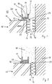
- a component 10 for example a door or window frame (in Fig. 1 shown schematically), is inserted in a wall opening and connected to the wall 11.
- a gap 12 between the peripheral side 13 of the component 10 and the wall 11 is by means of a Fugen Strukturllmaterials 14, z. B. a Gree filled out.
- On the outer side 15 directed towards the outside 16 of the component 10 is a per se known profile terminal strip 17 as a connection to an applied on the wall 11 outer cover layer, such as a plaster layer 18, respectively.
- the profile connection strip 17 has an approximately U-shaped cross section with a mounting base 19 and a front Einputzschenkel 20 and a rear Einputzschenkel 21.
- the profile connection strip 17 is fastened by means of a foam adhesive tape 22 made of plastic on the outer side 16 of the component 10, so that the foam adhesive tape 22 forms an intermediate layer between the component 10 and the mounting base 19 of the profile connection strip 17.
- the joint 23 thus allows 22 due to the elastic properties of the foam adhesive tape 22 compensating movements between the component 10 and the profile terminal strip 17 and the plaster layer 18, which has a different expansion behavior z. B. when exposed to heat, cold or moisture.
- the foam tape 22, z. B. a band with low elongation at break, at an increased relative movement of the component 10 relative to the profile terminal strip 17 does not compensate for the mutual offset by elastic deformation, so that it breaks, for example, within its structure.
- An upper part 24 of the foam tape 22 remains connected to the profile connection strip 17, while a lower part 25 remains connected to the component 10.
- the movement of the window frame or component 10 made of wood results from the swelling and shrinkage of the wood due to changing air humidity or temperature.
- the crack in the foam tape and the Fugenhellmaterial 14 or the Greschaum can tear and thus open this joint.
- the component 10 has moved toward the wall 11 and relative to the profile connection strip 17 due to a longitudinal expansion caused by the influence of heat.
- the foam tape 22, the z. B. is formed of harder foam material, for example, remains attached to the profile terminal block 17, but tears off with the adhesive layer 26 of the component 10, so that the joint 23 opens.
- the Fugen Stahlllmaterial 14 and the Grell in the rear joint 12 is compressed and can be damaged depending on its elastic properties or in a subsequent return movement of the component 10 when the rear gap 12 opens again.
- the component 10 has moved parallel to the wall 11 and from the profile connection strip 17 due to a caused by temperature or humidity change length reduction.
- the foam tape 22, the z. B. is made of a material with a low elongation at break, is torn off from the adhering firmly to the component 10 adhesive layer 26, so that the joint 23 is open.
- the joint filling material 14 or the Golfschaum in the rear gap 12 is sheared and torn in its structure, so that the rear gap 12 is opened.
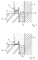
- Fig. 4 shows a profile connection strip 17 with a foam tape 22 according to the invention in the normal state without relative movements between the profile connection strip 17 and the component 10.
- Fig. 5 shows a position in which the component 10 z. B. has carried out a transverse movement of the wall 11 away due to cooling, while the plaster layer 18 has not changed or only slightly.
- the improved foam tape 22 with increased extensibility or elastic properties also expands during relatively large relative movements, so that it neither tears nor separates from an adhesive surface.
- the joint 23 remains closed and the sealing properties of the profile connection strip 17 are maintained, even if the joint filling material 14 or the filling foam in the rear joint 12 is torn.
- the improved foam strip 22 can bridge the offset without damage by its increased elasticity and extensibility, so that the joint 23 remains closed in this case.
- the foam tape 22 according to the invention expands to the required extent and deforms elastically, so that the joint 23 also remains closed here.
- the component 10 has moved by an increase in length parallel to the wall 11 and thereby the profile terminal strip 17th approximated.
- the improved foam tape 22 is elastically compressed and keeps the joint 23 closed. Even with an opposite return deformation of the component 10 in its initial position according to Fig. 4 or in the position according to Fig. 7 the elastically deforming, intact foam tape 22 can keep the joint 23 tightly closed.
- the foam adhesive tape 22 may have a color coding, which is characteristic of a property of the profile connection strip 17, for example, for the width of the profile connection strip 17. If this profile connection strip 17 z. B. is produced in three widths (the distance between the two Einputzschenkeln 20 and 21 sets the width), so z. B. a yellow colored foam adhesive tape 22 a narrow profile connection strip, a red colored foam tape a medium-width profile connection strip and a green-colored foam tape a wide profile connection strip.
Landscapes
- Engineering & Computer Science (AREA)
- Architecture (AREA)
- Civil Engineering (AREA)
- Structural Engineering (AREA)
- Building Environments (AREA)
Description
- Die Erfindung betrifft eine Profilanschlußleiste für einen Übergang von einem Bauteil zu einer Gebäudewand, wobei die Profilanschlußleiste ein Schaumband aufweist, das mittels Klebeverbindung unmittelbar oder mittelbar mit der Profilanschlußleiste verbunden und mit dem Bauteil unmittelbar oder mittelbar verbindbar ist und zum Ausgleich einer erhöhten Relativbewegung zwischen der Profilanschlußleiste und dem Bauteil eine erhöhte Elastizität aufweist.
- Aus der gattungsgemäßes
DE 200 08 712 U1 ist eine Proflanschlußleiste zum Abdichten einer Bewegungsfuge bekannt geworden, die mittels eines Schaumkunststoff-Klebebandes an einem Bauteil bzw. einem Fensterrahmen befestigt ist. Dieses übliche Schaumkunststoff-Klebeband kann Relativbewegungen zwischen dem Profilanschlußleistenprofil und dem Bauteil nur in geringem Maße aufnehmen. In der Praxis reißen die derzeit verwendeten Schaumkunststoff-Klebebänder häufig entweder an ihrer Verklebung mit dem Profilanschlußleistenprofil, dem Bauteil oder auch im Schaumband selbst, wenn Relativbewegungen auftreten. Damit ist die Fuge zwischen dem Bauteil und der Profilanschlußleiste bzw. der an die Profilanschlußleiste angrenzenden Putzschicht nicht mehr geschlossen bzw. abgedichtet Um die Eigenschaften der Profilanschlußleiste zum Ausgleichen von Relativbewegungen zu verbessern, ist vorgeschlagen worden (siehe Anspruch 3), einen Bauteilbefestigungsschenkel der Profilanschlußleiste mit zumindest einer Überhöhung oder Wölbung zu bilden, so daß nach dem Befestigen der Profilanschlußleiste auf einem Bauteil im Schaumkunststoff-Klebeband komprimierte und unkomprimierte Zonen entstehen, die beim Auftreten von Relativbewegungen und daraus folgenden Expansionsbewegungen und/oder Querbewegungen im Schaumstoff des Schaumkunststoff-Klebebandes durch elastischen Bewegungsausgleich eine dauerhafte Abdichtung gewährleisten. - Aus der
DE 87 15 604 U1 ist eine Schutzleiste beim Mauerputzvorgang bekannt geworden, die mittels eines weichen Bandes aus geschäumtem weichem Kunstharz mittels einer beidseitig aufgetragenen Klebeschicht an einem Fenster- oder Türrahmen befestigt ist. Das weiche Band soll die Schutzleiste davor schützen, daß sie sich bei Erschütterungen oder Verwindungen von Rahmenprofilen vom Putz löst. Konkrete Eigenschaften des weichen Bandes sind nicht angegeben. Die üblicherweise verwendeten Bänder können bei größeren Relativbewegungen das Lösen der Schutzleiste vom Putz nicht verhindern. - Aufgabe der Erfindung ist es, eine Profilanschlußleiste der eingangs genannten Art zu schaffen, die im Hinblick auf einen Ausgleich einer erhöhten Relativbewegung zwischen der Profilanschlußleiste und dem Bauteil verbessert ist.
- Die Aufgabe wird bei der oben genannten Profilanschlußleiste erfindungsgemäß dadurch gelöst, dass das Schaumband zum Ausgleich einer erhöhten Relativbewegung zwischen der Profilanschlußleiste und dem Bauteil eine erhöhte Bruchdehnung aufweist, wobei das Schaumband eine Bruchdehnung in Längsrichtung der Profilanschlußleiste von mindestens 200 % und insbesondere von mindestens 300 % und/oder eine Bruchdehnung in Querrichtung der Profilanschlußleiste von mindestens 200 % und insbesondere von mindestens 300 % aufweist.
- Unter erhöhter Relativbewegung wird eine Relativbewegung von solchem Ausmaß verstanden, die bei den üblicherweise verwendeten Schaumbändern zu einer Beschädigung bzw. zu einem Reißen des Schaumbandes und damit zu einem Öffnen der Fuge führt. Durch die erhöhte Elastizität bzw. Bruchdehnung kann sich das Schaumband in dem erforderlichen Ausmaß elastisch verformen und dehnen, ohne daß es zu einer Beschädigung oder zu einem Reißen des Schaumbandes kommt. Das Schaumband ist z. B. durch aufgebrachten Klebstoff verklebt oder es ist ein Schaumklebeband, das an zumindest einer Oberseite eine Klebeschicht aufweist.
- Das erfindungsgemäße Schaumband ist jedenfalls kein Kompriband, das mit Vorspannung bzw. Kompression eingebaut wird und in Einbaustellung expandiert und zu diesem bauartbedingten Zweck eine hohe Elastizität besitzt. Ein derartiges Kompriband enthält die in der
DE 44 39 075 A1 offenbarte Abschlußleiste. Das Kompriband ist ein spezieller, aus bituminiertem Schaumstoff hergestellter Dichtungsstreifen, der an der Abschlußleiste vor deren Einbau in zusammengedrückter Lage gehalten ist und in Einbaulage freigegeben ist, so daß er um ein Vielfaches seiner Kompressionsdicke expandiert und sich federnd gegen einen Fensterrahmen legt und einen dichten Abschluß bilden kann. Er ist jedoch nicht an dem Fensterrahmen befestigt und hat somit keine Haltefunktion für die Abschlußleiste, Diese zweiteilig aufgebaute Abschlußleiste ist teuer in der Herstellung und aufwendig in der Verarbeitung. - Während bei den bekannten Profilleisten mit Schaumband oder Schaumklebeband der Hersteller der Profilleisten auf Standardschaumbänder zurückgreift, die üblichen Schaumstoff mit Standardeigenschaften verwenden, ist bei der erfindungsgemäßen Profilanschlußleiste somit erstmals das Schaumband hinsichtlich derjenigen Eigenschaften verbessert worden, die zum Ausgleichen erhöhter Relativbewegungen besonders relevant sind. Damit befaßt sich erstmals der Hersteller der Profilleiste mit den Eigenschaften des Schaumes für das Schaumband, die ansonsten der Hersteller des Schaumes festlegt und der Hersteller des Schaumbandes für Standardschaumbänder übernimmt, ohne sie im Hinblick auf spezielle Eigenschaften zu überprüfen oder zu optimieren. Der Hersteller von Schaumklebebändern produziert diese mit bestimmten Eigenschaften z. B. hinsichtlich Kleberart, Temperaturbereich für die Anwendung, Anfangsklebekraft oder Beständigkeit gegen Weichmacher, so daß primär bestimmte Eigenschaften des Klebstoffes gewählt werden. Die Dehnungsfähigkeit des Schaumes bzw. des Schaumbandes ist dabei nicht Gegenstand einer bewußten Auswahl.
- Vorteilhafte Ausgestaltungen der Erfindung sind in den Unteransprüchen angegeben.
- Statt einer unmittelbaren Befestigung des Schaumbandes bzw. Schaumklebebandes an dem Bauteil bzw. an der Profilleiste kann bei der mittelbaren Verbindung eine Zwischenschicht zwischen dem Schaumband und der Profilanschlußleiste bzw. zwischen dem Schaumband und dem Bauteil angeordnet sein. Die Zwischenschicht ist beispielsweise ein Teil der Profilanschlußleiste wie z. B. ein Schenkel.
- Während die derzeit verwendeten Schaumbänder nach Messung des Anmelders eine niedrige Bruchdehnung (nach DIN ISO 1926) von bis etwa 170% in Längsrichtung wie auch in Querrichtung aufweisen, hat das erfindungsgemäße Schaumband eine erhöhte Bruchdehnung in Längsrichtung der Profilanschlußleiste und/oder in Querrichtung größer 200% und insbesondere größer 300%. Damit gestattet das Schaumband große Relativbewegungen und hält aufgrund seiner großen Dehnfähigkeit die Fuge geschlossen.
- Des weiteren haben die derzeit verwendeten Schaumbänder nach Messung des Anmelders eine hohe Stauchhärte (nach DIN ISO 844) von mindestens 25 kPa bei 10% Stauchung und mindestens 120 kPa bei 50% Stauchung, Die Stauchhärte als Widerstandskraft gegen eine Stauchung stellt ein Maß für die übertragbare Dehnungskraft dar. Das erfindungsgemäße Schaumband hat vorzugsweise eine Stauchhärte bei 10% Stauchung von kleiner 25 kPa, insbesondere kleiner 22 kPa und bevorzugt kleiner als 14 kPa und bei 50% Stauchung von kleiner 120 kPa, insbesondere kleiner 110 kPa und bevorzugt kleiner als 80 kPa. Geringere Druckkräfte bedeuten auch geringere Dehnungskräfte mit weniger Verformungswiderstand, so daß die Profilanschlußleiste nicht aus dem Putz herausgerissen wird.
- Während die derzeit verwendeten Schaumbänder nach Messung des Anmelders eine Shore-Härte 0 von mindestens 20 und eine Shore-Härte 00 von mindestens 59 aufweisen und somit eine hohe Dehnungskraft besitzen, hat das erfindungsgemäße Schaumband vorzugsweise eine Shore-Härte 0 von kleiner als 20, insbesondere kleiner als 18 und bevorzugt kleiner als 12 und eine Shore-Härte 00 von kleiner als 59, insbesondere kleiner als 57 und bevorzugt kleiner als 49. Ein Schaumband mit geringer Shore-Härte ist vergleichsweise weich, so daß geringere Kräfte bei der Dehnung zu überwinden sind. Somit wird verhindert, daß die Profilanschlußleiste aus dem Putz herausgerissen wird.
- Sowohl die Shore-Härte wie auch die Stauchhärte sind ein Maß für die Weichheit des Schaumbandes und somit für die im Schaumband auftretenden Dehnungskräfte.
- Sehr gute zähelastische Eigenschaften werden durch Zusatzstoffe oder Inhaltsstoffe im Schaumgrundmaterial bei der Extrusion des Schaumes erzielt.
- Bei der Extrusion des Schaumes wird bevorzugt eine Rohdichte zwischen 67 kg/m3 (Expansion 15) bis 33 kg/m3 (Expansion 30) und insbesondere 50 kg/m3 (Expansion 20) hergestellt, z. B. Aleveolit TEE 2000 mit 50 kg/m3 (Bruchdehnung längs 275% und quer 335%) oder Alveolit TME-S 2000 mit 50 kg/m3 (Bruchdehnung längs 400% und quer 495%).
- Die Profilanschlußleiste ist beispielsweise ein Leibungsanschlußprofil, ein Dehnungsfugenprofil, ein Putzabschlußprofil oder ein Dachbelüftungsprofil. Die Dicke des Schaumbandes beträgt bei einem Leibungsanschlußprofil bevorzugt 2 bis 4 mm und insbesondere 3 mm.
- Bei einer Dicke des Schaumbandes von 3 mm gestattet eine Bruchdehnung von 300% ein absolute Dehnung von 9 mm. Aus optischen Gründen wie auch wegen des nachteiligen Einflusses der UV-Strahlung ist ein vergleichsweise dünnes Schaumband angestrebt. Um dennoch ein hohes absolutes Dehnungsmaß zu ermöglichen, wird die Bruchdehnung durch Zugabe entsprechender Zusatzstoffe bei der Herstellung des Schaumes hoch eingestellt. Im Stand der Technik wird z. B. ein 3 mm dickes Schaumband mit einer Bruchdehnung von 170% verwendet. Das daraus resultierende absolute Dehnungsmaß von 5,1 mm erweist sich in der Praxis häufig als nicht ausreichend. Daher können mit dem erfindungsgemäßen Schaumband bei einer Bruchdehnung von größer 200%, insbesondere größer 250%, 300% oder sogar 400% absolute Dehnungsmaße von 6 mm, 7,5 mm, 9 mm bis hin zu 12 mm erreicht werden. Die Zugabe von Zusatzstoffen ist kostengünstiger wie die Verwendung eines ansonsten dickeren Schaumbandes. Ein dickeres Schaumband hat auch den Nachteil, daß die am Bauteil befestigte Profilanschlußleiste beim Einputzen bei der Verwendung als Abzugskante gekippt und weggedrückt werden kann.
- Des weiteren kann die Profilanschlußleiste, insbesondere die Zwischenschicht bzw. das Schaumband, eine optische Kennung, insbesondere eine bestimmte Farbe, aufweisen, so daß die Handhabung bei der Auswahl der korrekten Profilanschlußleiste erleichtert wird. So werden Verwechslungen der unterschiedlichen Profilanschlußeisten, insbesondere bei Handhabung durch Hilfskräfte, vermieden und die Abdichtung der Fugen technisch richtig erstellt.
- Vorzugsweise ist die Profilanschlußleiste bzw. das Schaumband aus Kunststoff hergestellt. Unter den Kunststoffen sind Polyvinylchlorid, Polyolefin, Polyethylen, Polypropylen, Polystyrol und Polyurethan besonders bevorzugt. Der Querschnitt des Kunststoffanteils der Profilanschlußleiste bleibt über ihre Länge gleich, so daß die Profilanschlußleiste im Extrusionsverfahren kostengünstig hergestellt werden kann.
- Die Profilanschlußleiste wird z. B. auf der Oberfläche einer Wand verwendet, z. B. beim Übergang von Sichtbeton zu einem Fenster, oder sie ist in der Oberfläche der Wand eingebettet, wie z. B. bei Putz, Wärmedämm-Verbundsysteme, Trokkenbau, Fliesen, Blech und dergleichen.
- Nachfolgend wird ein Ausführungsbeispiel einer Profilanschlußleiste unter Bezugnahme auf die Zeichnung näher erläutert. Es zeigt:
- Fig. 1
- in einer Querschnittansicht eine Profilanschlußleiste des Standes der Technik in einer Abdichtungsanordnung zwischen einer Putzschicht und einem Bauteil, wobei das Schaumband aufgrund übermäßiger relativer Bewegung des Bauteils gegenüber der Profilanschlußleiste gerissen ist;
- Fig. 2
- in einer Querschnittansicht gemäß
Fig. 1 die Profilanschlußleiste des Standes der Technik, wobei das Schaumband vom Bauteil abgerissen ist; - Fig. 3
- in einer Querschnittansicht gemäß
Fig. 1 die Profilanschlußleiste des Standes der Technik, wobei sich das Schaumband von der am Bauteil anhaftenden Klebeschicht gelöst hat; - Fig. 4
- in einer Querschnittansicht eine erfindungsgemäße Profilanschlußleiste in einer Abdichtungsanordnung zwischen einer Putzschicht und einem Bauteil in normaler Zuordnung;
- Fig. 5
- in einer Querschnittansicht gemäß
Fig. 4 die Profilanschlußleiste mit einem aufgrund einer Bauteilbewegung verformtem Schaumband; - Fig. 6
- in einer Querschnittansicht gemäß
Fig. 4 die Profilanschlußleiste mit dem aufgrund einer gegenüberFig. 5 entgegengesetzt gerichteten Bauteilbewegung verformtem Schaumband; - Fig. 7
- in einer Querschnittansicht gemäß
Fig. 4 die Profilanschlußleiste mit dem verformtem Schaumband, wobei sich das Bauteil von der Profilanschlußleiste entfernt hat; und - Fig. 8
- in einer Querschnittansicht gemäß
Fig. 4 die Profilanschlußleiste mit dem verformtem Schaumband, wobei sich das Bauteil der Profilanschlußleiste angenähert hat. - Ein Bauteil 10, beispielsweise ein Tür- oder Fensterrahmen (in
Fig. 1 schematisch dargestellt), ist in einer Wandöffnung eingesetzt und mit der Wand 11 verbunden. Eine Fuge 12 zwischen der Umfangsseite 13 des Bauteils 10 und der Wand 11 ist mittels eines Fugenfüllmaterials 14, z. B. eines Füllschaumes, ausgefüllt. An der zu einem Außenraum 15 hin gerichteten Außenseite 16 des Bauteils 10 ist eine an sich bekannte Profilanschlußleiste 17 als Anschluß zu einer auf der Wand 11 aufgebrachten äußeren Deckschicht, beispielsweise einer Putzschicht 18, angeordnet. Die Profilanschlußleiste 17 weist einen in etwa U-förmigen Querschnitt mit einer Befestigungsbasis 19 sowie einem vorderen Einputzschenkel 20 und einem hinteren Einputzschenkel 21 auf. Die Profilanschlußleiste 17 ist mittels eines aus Kunststoff hergestellten Schaumklebebands 22 an der Außenseite 16 des Bauteils 10 befestigt, so daß das Schaumklebeband 22 eine Zwischenschicht zwischen dem Bauteil 10 und der Befestigungsbasis 19 der Profilanschlußleiste 17 bildet. - Beim Aufbringen der Putzschicht 18 auf die Wand 11 dient der vordere Einputzschenkel 20 als Einputzhilfe für ein Putzwerkzeug und er gibt die Dicke der Putzschicht 18 vor. Eine zwischen der Profilanschlußleiste 17 und dem Bauteil 10 gebildete Fuge 23 ist durch das Schaumklebeband 22 ausgefüllt bzw. abgedichtet.
- Die Fuge 23 ermöglicht somit aufgrund der in gewissem Umfang elastischen Eigenschaften des Schaumklebebandes 22 Ausgleichsbewegungen zwischen dem Bauteil 10 und der Profilanschlußleiste 17 bzw. der Putzschicht 18, die ein unterschiedliches Ausdehnungsverhalten z. B. bei Einwirkung von Wärme, Kälte oder Feuchtigkeit aufweisen. Wenn sich das Bauteil 10, beispielsweise ein Fensterrahmen aus Holz, zusammenzieht (siehe
Fig. 1 , Bewegung in Richtung des Pfeils senkrecht von der Wand 11 weg), kann das Schaumband 22, z. B. ein Band mit geringer Bruchdehnung, bei einer erhöhten Relativbewegung des Bauteils 10 gegenüber der Profilanschlußleiste 17 den gegenseitigen Versatz durch elastische Verformung nicht ausgleichen, so daß es beispielsweise innerhalb seines Gefüges reißt. Ein oberer Teil 24 des Schaumbandes 22 bleibt mit der Profilanschlußleiste 17 verbunden, während ein unterer Teil 25 mit dem Bauteil 10 verbunden bleibt. - Die Bewegung des aus Holz hergestellten Fensterrahmens bzw. Bauteils 10 resultiert aus dem Quellen und Schwinden des Holzes durch sich ändernde Luftfeuchtigkeit oder Temperatur. Zusätzlich zu dem Riß im Schaumband kann auch das Fugenfüllmaterial 14 bzw. der Füllschaum reißen und damit diese Fuge öffnen.
- Bei dem in
Fig. 2 dargestellten Beispiel des Standes der Technik hat sich das Bauteil 10 aufgrund einer durch Wärmeeinfluß bewirkten Längenausdehnung zur Wand 11 hin und relativ zur Profilanschlußleiste 17 bewegt. Das Schaumband 22, das z. B. aus härterem Schaummaterial gebildet ist, bleibt beispielsweise an der Profilanschlußleiste 17 befestigt, reißt jedoch mit der Klebeschicht 26 von dem Bauteil 10 ab, so daß sich die Fuge 23 öffnet. Das Fugenfüllmaterial 14 bzw. der Füllschaum in der hinteren Fuge 12 wird komprimiert und kann dabei in Abhängigkeit seiner elastischen Eigenschaften geschädigt werden oder bei einer anschließenden Rückbewegung des Bauteils 10, wenn sich die hintere Fuge 12 wieder öffnet. - Bei dem in
Fig. 3 dargestellten Beispiel des Standes der Technik hat sich das Bauteil 10 aufgrund einer durch Temperatur- oder Feuchteänderung bewirkten Längenverkürzung parallel zur Wand 11 und von der Profilanschlußleiste 17 weg bewegt. Das Schaumband 22, das z. B. aus einem Material mit geringer Bruchdehnung hergestellt ist, ist von der fest am Bauteil 10 anhaftenden Klebeschicht 26 abgerissen, so daß die Fuge 23 offen ist. Das Fugenfüllmaterial 14 bzw. der Füllschaum in der hinteren Fuge 12 ist abgeschert und in seiner Struktur gerissen, so daß auch die hintere Fuge 12 geöffnet ist. -
Fig. 4 zeigt eine Profilanschlußleiste 17 mit einem erfindungsgemäßen Schaumband 22 im Normalzustand ohne Relativbewegungen zwischen der Profilanschlußleiste 17 und dem Bauteil 10. Demgegenüber zeigtFig. 5 eine Stellung, in der das Bauteil 10 z. B. aufgrund einer Abkühlung eine Querbewegung von der Mauer 11 weg ausgeführt hat, während sich die Putzschicht 18 nicht oder nur unwesentlich verändert hat. Das verbesserte Schaumband 22 mit erhöhter Dehnungsfähigkeit bzw. elastischen Eigenschaften dehnt sich auch bei größeren Relativbewegungen, so daß es weder reißt noch sich von einer Klebeoberfläche löst. Damit bleibt die Fuge 23 geschlossen und die Abdichteigenschaften der Profilanschlußleiste 17 erhalten, auch wenn das Fugenfüllmaterial 14 bzw. der Füllschaum in der hinteren Fuge 12 gerissen ist. - Auch bei einem Versatz des Bauteils 10 z. B. aufgrund einer Erwärmung und einer daraus resultierenden Querbewegung zur Mauer 11 hin (siehe
Fig. 6 ), während sich die Putzschicht 18 nicht oder nur unwesentlich verändert hat, kann das verbesserte Schaumband 22 durch seine erhöhte Elastizität und Dehnungsfähigkeit den Versatz ohne Beschädigung überbrücken, so daß die Fuge 23 auch in diesem Fall geschlossen bleibt. - Wenn sich das Bauteil 10 entsprechend der in
Fig. 3 gezeigten Situation aufgrund einer durch Temperatur- oder Feuchteänderung bewirkten Längenverkürzung parallel zur Wand 11 bewegt und dabei von der Profilanschlußleiste 17 entfernt hat (sieheFig. 7 ), dehnt sich das erfindungsgemäße Schaumband 22 im erforderlichen Maß und verformt sich elastisch, so daß die Fuge 23 auch hier geschlossen bleibt. - Bei der in
Fig. 8 gezeigten Situation hat sich das Bauteil 10 durch eine Längenvergrößerung parallel zur Wand 11 bewegt und dabei der Profilanschlußleiste 17 angenähert. Das verbesserte Schaumband 22 wird elastisch gestaucht und hält die Fuge 23 geschlossen. Auch bei einer entgegengesetzten Rückverformung des Bauteils 10 in seine Ausgangsstellung gemäßFig. 4 oder in die Stellung gemäßFig. 7 kann das sich elastisch verformende, unversehrte Schaumband 22 die Fuge 23 dicht geschlossen halten. - Die in den Figuren dargestellten Bewegungen des Bauteils 10 relativ zur Wand 11 und zur Profilanschlußleiste 17 bzw. der Putzschicht 18 sind vereinfacht schematisch dargestellt. In der Realität können auch Überlagerungen der dargestellten Bewegungen, insbesondere in den Eckbereichen von Rahmen als Bauteilen, auftreten.
- Das Schaumklebeband 22 kann eine Farbkennzeichnung aufweisen, die für eine Eigenschaft der Profilanschlußleiste 17 charakteristisch ist, beispielsweise für die Breite der Profilanschlußleiste 17. Wenn diese Profilanschlußleiste 17 z. B. in drei Breiten hergestellt wird (der Abstand zwischen den beiden Einputzschenkeln 20 und 21 legt die Breite fest), so bezeichnet z. B. ein gelb gefärbtes Schaumklebeband 22 eine schmale Profilanschlußleiste, ein rot gefärbtes Schaumklebeband eine mittelbreite Profilanschlußleiste und ein grün gefärbtes Schaumklebeband eine breite Profilanschlußleiste.
Bezugszeichenliste 10 Bauteil 19 Befestigungsbasis 11 Wand 20 vorderer Einputzschenkel 12 Fuge 21 hinterer Einputzschenkel 13 Umfangsseite 22 Schaumklebeband 14 Fugenfüllmaterial 23 Fuge 15 Außenraum 24 oberer Teil 16 Außenseite 25 unterer Teil 17 Profilanschlußleiste 26 Klebeschicht 18 Putzschicht
Claims (9)
- Profilanschlußleiste (17) für einen Übergang von einem Bauteil (10) zu einer Gebäudewand (11),
wobei die Profilanschlußleiste (17) ein Schaumband (22) aufweist, das mittels Klebeverbindung unmittelbar oder mittelbar mit der Profilanschlußleiste (17) verbunden und mit dem Bauteil (10) unmittelbar oder mittelbar verbindbar ist und zum Ausgleich einer erhöhten Relativbewegung zwischen der Profilanschlußleiste (17) und dem Bauteil (10) eine erhöhte Elastizität aufweist,
dadurch gekennzeichnet,
dass das Schaumband (22) zum Ausgleich einer erhöhten Relativbewegung zwischen der Profilanschlußleiste (17) und dem Bauteil (10) eine erhöhte Bruchdehnung aufweist, wobei das Schaumband (22) eine Bruchdehnung in Längsrichtung der Profilanschlußleiste (17) von mindestens 200% und insbesondere von mindestens 300% und/oder eine Bruchdehnung in Querrichtung der Profilanschlußleiste (17) von mindestens 200% und insbesondere von mindestens 300% aufweist. - Profilanschlußleiste nach Anspruch 1,
dadurch gekennzeichnet, dass bei der mittelbaren Verbindung eine Zwischenschicht zwischen dem Schaumband (22) und der Profilanschlußleiste (17) bzw. zwischen dem Schaumband (22) und dem Bauteil (10) angeordnet ist. - Profilanschlußleiste nach Anspruch 1 oder 2,
dadurch gekennzeichnet, dass das Schaumband (22) eine Shore-Härte 0 von kleiner 20 und Insbesondere kleiner 16 aufweist. - Profilanschlußleiste nach einem der Ansprüche 1 bis 3,
dadurch gekennzeichnet, dass das Schaumband (22) eine Shore-Härte 00 von kleiner 59 und insbesondere kleiner 55 aufweist. - Proflanschlußleiste nach einem der Ansprüche 1 bis 4,
dadurch gekennzeichnet, dass das Schaumband (22) eine Stauchhärte bei 10% Stauchung kleiner 25 kPa, insbesondere kleiner 19 kPa aufweist. - Profilanschlußleiste nach einem der Ansprüche 1 bis 5,
dadurch gekennzeichnet, dass das Schaumband (22) eine Stauchhärte bei 50% Stauchung kleiner 120 kPa, insbesondere kleiner 100 kPA aufweist. - Profilanschlußleiste nach einem der Ansprüche 1 bis 6,
dadurch gekennzeichnet, dass das Schaumband (22) ein ein- oder doppelseitig klebendes Schaumklebeband ist. - Profilanschlußleiste nach einem der Ansprüche 1 bis 7,
dadurch gekennzeichnet, dass die Profilanschlußleiste (17) ein Leibungsanschlußprofil, ein Dehnungsfugenprofil, ein Putzabschlußprofil oder ein Dachbelüftungsprofil ist. - Profilanschlußleiste nach einem der Ansprüche 1 bis 8,
dadurch gekennzeichnet, dass die Profilanschlußleiste (17) aus Kunststoff und/oder das Schaumband (22) aus Polyolefin oder Polyethylen hergestellt Ist.
Applications Claiming Priority (2)
| Application Number | Priority Date | Filing Date | Title |
|---|---|---|---|
| DE10317414 | 2003-04-15 | ||
| DE2003117414 DE10317414A1 (de) | 2003-04-15 | 2003-04-15 | Profilanschlußleiste für einen Übergang von einem Bauteil zu einer Gebäudewand |
Publications (2)
| Publication Number | Publication Date |
|---|---|
| EP1469139A1 EP1469139A1 (de) | 2004-10-20 |
| EP1469139B1 true EP1469139B1 (de) | 2016-04-13 |
Family
ID=32892359
Family Applications (1)
| Application Number | Title | Priority Date | Filing Date |
|---|---|---|---|
| EP04008917.9A Revoked EP1469139B1 (de) | 2003-04-15 | 2004-04-15 | Profilanschlussleiste für einen Übergang von einem Bauteil zu einer Gebäudewand |
Country Status (2)
| Country | Link |
|---|---|
| EP (1) | EP1469139B1 (de) |
| DE (1) | DE10317414A1 (de) |
Families Citing this family (3)
| Publication number | Priority date | Publication date | Assignee | Title |
|---|---|---|---|---|
| DE102006002054A1 (de) * | 2006-01-16 | 2007-07-19 | Konrad Lehrhuber | Abdichtungsanordnung und Profilleiste für eine Abdichtungsanordnung |
| DE202007000895U1 (de) | 2007-01-16 | 2007-04-12 | Lehrhuber Konrad | Profilanschlussleiste für einen Übergang von einem Bauteil zu einer Gebäudewand |
| DE202009002918U1 (de) | 2009-03-02 | 2010-07-22 | Lehrhuber, Konrad | Dichtvorrichtung zur Fugenabdichtung zwischen zwei Bauteilen |
Citations (7)
| Publication number | Priority date | Publication date | Assignee | Title |
|---|---|---|---|---|
| DE8715604U1 (de) | 1987-11-25 | 1988-01-14 | Braun, August, 6653 Blieskastel | Schutzleiste beim Mauerputzvorgang |
| JPH05111974A (ja) | 1991-10-23 | 1993-05-07 | Yoshizawa:Kk | 緩衝性被覆材 |
| DE19614109C1 (de) * | 1996-04-10 | 1997-06-12 | Gima Gipser Und Malerbedarf Gm | Laibungsanschlußprofil für Fenster- und Türöffnungen |
| DE19605467A1 (de) * | 1996-02-14 | 1997-08-21 | Braun August | Anputzleiste für Fensterstöcke, Türstöcke oder dergleichen am Übergang zu Putz |
| EP1010852A1 (de) | 1998-12-15 | 2000-06-21 | Schlegel BVBA | Dichtungsstreifen sowie sein Herstellungs- und Einsetzverfahren |
| DE20008712U1 (de) | 2000-05-16 | 2000-08-03 | Lehrhuber, Konrad, Dipl.-Ing. (FH), 84144 Geisenhausen | Profilleiste zum Abdichten einer Bewegungsfuge zwischen einem Bauteil und einer Putzschicht |
| JP2001089742A (ja) | 1999-09-20 | 2001-04-03 | Sekisui Chem Co Ltd | シーリングテープ |
Family Cites Families (5)
| Publication number | Priority date | Publication date | Assignee | Title |
|---|---|---|---|---|
| DE1182410B (de) * | 1959-06-24 | 1964-11-26 | Skanska Aettikfabriken Ab | Abdeckung fuer die Raender von Verkleidungsplatten mit Profilleisten |
| DE4020230A1 (de) * | 1989-06-30 | 1991-01-03 | Heribert Hiendl | Fugendichtungsband |
| DE4439075C2 (de) | 1994-11-02 | 1999-09-16 | Maisch F Protektorwerk | Abschlußleiste zum Abdichten eines Rahmenteils gegenüber einer Laibung |
| DE20009674U1 (de) * | 1999-06-09 | 2000-09-14 | Hanno-Werk GmbH & Co. KG, 30880 Laatzen | Mehrlagiges Dichtungsband zum Abdichten von Fugen |
| DE10066070A1 (de) * | 2000-05-16 | 2004-06-03 | Lehrhuber, Konrad, Dipl.-Ing. (FH) | Profilleiste zum Abdichten einer Bewegungsfuge zwischen einem Bauteil und einer Putzschicht |
-
2003
- 2003-04-15 DE DE2003117414 patent/DE10317414A1/de not_active Ceased
-
2004
- 2004-04-15 EP EP04008917.9A patent/EP1469139B1/de not_active Revoked
Patent Citations (8)
| Publication number | Priority date | Publication date | Assignee | Title |
|---|---|---|---|---|
| DE8715604U1 (de) | 1987-11-25 | 1988-01-14 | Braun, August, 6653 Blieskastel | Schutzleiste beim Mauerputzvorgang |
| JPH05111974A (ja) | 1991-10-23 | 1993-05-07 | Yoshizawa:Kk | 緩衝性被覆材 |
| DE19605467A1 (de) * | 1996-02-14 | 1997-08-21 | Braun August | Anputzleiste für Fensterstöcke, Türstöcke oder dergleichen am Übergang zu Putz |
| EP0880630B1 (de) | 1996-02-14 | 2003-05-21 | August Braun | Anputzleiste für fensterstöcke, türstöcke oder dergleichen am übergang zu putz |
| DE19614109C1 (de) * | 1996-04-10 | 1997-06-12 | Gima Gipser Und Malerbedarf Gm | Laibungsanschlußprofil für Fenster- und Türöffnungen |
| EP1010852A1 (de) | 1998-12-15 | 2000-06-21 | Schlegel BVBA | Dichtungsstreifen sowie sein Herstellungs- und Einsetzverfahren |
| JP2001089742A (ja) | 1999-09-20 | 2001-04-03 | Sekisui Chem Co Ltd | シーリングテープ |
| DE20008712U1 (de) | 2000-05-16 | 2000-08-03 | Lehrhuber, Konrad, Dipl.-Ing. (FH), 84144 Geisenhausen | Profilleiste zum Abdichten einer Bewegungsfuge zwischen einem Bauteil und einer Putzschicht |
Non-Patent Citations (2)
| Title |
|---|
| INOVA GMBH: "Technisches Datenblatt, Artikel-Nr. 614, 10m Quell-Schaumband 10x10 mm, INOVA GmbH", 30 January 2014 (2014-01-30), XP055222000, Retrieved from the Internet <URL:http://www.inova-web.de/media/TDS/SelbstklebendeProdukteDichtbaender/614-10-m-Quell-Schaumband-10-x-10-mm.pdf> [retrieved on 20151019] * |
| LOHMANN: "Datenblatt Duplocoll 5110", pages: 1 - 3 * |
Also Published As
| Publication number | Publication date |
|---|---|
| DE10317414A1 (de) | 2004-11-25 |
| EP1469139A1 (de) | 2004-10-20 |
Similar Documents
| Publication | Publication Date | Title |
|---|---|---|
| EP2404008B1 (de) | Dichtanordnung an einer fuge an einem bauwerk | |
| EP1811111B1 (de) | Fensterlaibung mit einem Fensterrahmen und einem Dichtstreifen | |
| EP1808565B1 (de) | Abdichtungsanordnung und Profilleiste für eine Abdichtungsanordnung | |
| EP2492428B1 (de) | Anputzleiste sowie Bauwerksecke mit Anputzleiste | |
| DE10066070A1 (de) | Profilleiste zum Abdichten einer Bewegungsfuge zwischen einem Bauteil und einer Putzschicht | |
| DE20008712U1 (de) | Profilleiste zum Abdichten einer Bewegungsfuge zwischen einem Bauteil und einer Putzschicht | |
| EP2492429B1 (de) | Anputzleiste sowie Bauwerksecke mit Anputzleiste | |
| EP1627982B1 (de) | Anschlussprofil | |
| EP1722064B1 (de) | Anschlussprofilleiste, insbesondere Laibungsanschlussprofilleiste | |
| EP1469139A1 (de) | Profilanschlussleiste für einen Übergang von einem Bauteil zu einer Gebäudewand | |
| EP3088651B1 (de) | Abdichtungsanordnung für fugen zwischen einem bauteil und einer wand und profilleiste für eine solche abdichtungsanordnung | |
| EP4130419B1 (de) | Dichtstreifen | |
| DE102009004690B4 (de) | Anschlussprofilleiste, insbesondere Laibungsanschlussprofilleiste | |
| EP1691018B1 (de) | Profilleiste | |
| DE102008057798A1 (de) | Zweiteiliges Laibungsanschlussprofil | |
| EP1426540B1 (de) | Abdichtungsanordnung für Fugen zwischen einem Bauteil und einer Wand und Profilleiste für eine solche Abdichtungsanordnung | |
| AT8398U1 (de) | Zweiteiliges laibungsanschlussprofil | |
| DE102006038695A1 (de) | Profilleiste zur Aufnahme von Bewegungen | |
| EP2614204A1 (de) | Isolierglaselement | |
| DE102015110391A1 (de) | Kunststoff-Putzleiste sowie Dämmabschluss-Kunststoff-Sockelleiste | |
| EP1835116B1 (de) | Leiste | |
| DE102021100706A1 (de) | Anputzleiste und Verfahren zur Herstellung derselben | |
| DE202011005388U1 (de) | Fensterbank | |
| EP2514904A2 (de) | Fensterbank | |
| AT13200U1 (de) | Fensterleiste mit integriertem dichtungsband |
Legal Events
| Date | Code | Title | Description |
|---|---|---|---|
| PUAI | Public reference made under article 153(3) epc to a published international application that has entered the european phase |
Free format text: ORIGINAL CODE: 0009012 |
|
| 17P | Request for examination filed |
Effective date: 20040729 |
|
| AK | Designated contracting states |
Kind code of ref document: A1 Designated state(s): AT BE BG CH CY CZ DE DK EE ES FI FR GB GR HU IE IT LI LU MC NL PL PT RO SE SI SK TR |
|
| AX | Request for extension of the european patent |
Extension state: AL HR LT LV MK |
|
| AKX | Designation fees paid |
Designated state(s): AT BE BG CH CY CZ DE DK EE ES FI FR GB GR HU IE IT LI LU MC NL PL PT RO SE SI SK TR |
|
| 17Q | First examination report despatched |
Effective date: 20080502 |
|
| GRAP | Despatch of communication of intention to grant a patent |
Free format text: ORIGINAL CODE: EPIDOSNIGR1 |
|
| INTG | Intention to grant announced |
Effective date: 20151102 |
|
| GRAS | Grant fee paid |
Free format text: ORIGINAL CODE: EPIDOSNIGR3 |
|
| GRAA | (expected) grant |
Free format text: ORIGINAL CODE: 0009210 |
|
| RAP1 | Party data changed (applicant data changed or rights of an application transferred) |
Owner name: LEHRHUBER, KONRAD, DIPL.-ING. |
|
| RIN1 | Information on inventor provided before grant (corrected) |
Inventor name: LEHRHUBER, KONRAD, DIPL.-ING. |
|
| AK | Designated contracting states |
Kind code of ref document: B1 Designated state(s): AT BE BG CH CY CZ DE DK EE ES FI FR GB GR HU IE IT LI LU MC NL PL PT RO SE SI SK TR |
|
| REG | Reference to a national code |
Ref country code: GB Ref legal event code: FG4D Free format text: NOT ENGLISH |
|
| REG | Reference to a national code |
Ref country code: AT Ref legal event code: REF Ref document number: 790347 Country of ref document: AT Kind code of ref document: T Effective date: 20160415 Ref country code: CH Ref legal event code: EP |
|
| REG | Reference to a national code |
Ref country code: DE Ref legal event code: R082 Ref document number: 502004015161 Country of ref document: DE Representative=s name: FISCHER & KONNERTH PATENTANWAELTE PARTNERSCHAF, DE |
|
| REG | Reference to a national code |
Ref country code: IE Ref legal event code: FG4D Free format text: LANGUAGE OF EP DOCUMENT: GERMAN |
|
| REG | Reference to a national code |
Ref country code: DE Ref legal event code: R096 Ref document number: 502004015161 Country of ref document: DE |
|
| PG25 | Lapsed in a contracting state [announced via postgrant information from national office to epo] |
Ref country code: BE Free format text: LAPSE BECAUSE OF NON-PAYMENT OF DUE FEES Effective date: 20160430 |
|
| REG | Reference to a national code |
Ref country code: NL Ref legal event code: MP Effective date: 20160413 |
|
| PG25 | Lapsed in a contracting state [announced via postgrant information from national office to epo] |
Ref country code: PL Free format text: LAPSE BECAUSE OF FAILURE TO SUBMIT A TRANSLATION OF THE DESCRIPTION OR TO PAY THE FEE WITHIN THE PRESCRIBED TIME-LIMIT Effective date: 20160413 Ref country code: NL Free format text: LAPSE BECAUSE OF FAILURE TO SUBMIT A TRANSLATION OF THE DESCRIPTION OR TO PAY THE FEE WITHIN THE PRESCRIBED TIME-LIMIT Effective date: 20160413 Ref country code: FI Free format text: LAPSE BECAUSE OF FAILURE TO SUBMIT A TRANSLATION OF THE DESCRIPTION OR TO PAY THE FEE WITHIN THE PRESCRIBED TIME-LIMIT Effective date: 20160413 |
|
| PG25 | Lapsed in a contracting state [announced via postgrant information from national office to epo] |
Ref country code: GR Free format text: LAPSE BECAUSE OF FAILURE TO SUBMIT A TRANSLATION OF THE DESCRIPTION OR TO PAY THE FEE WITHIN THE PRESCRIBED TIME-LIMIT Effective date: 20160714 Ref country code: SE Free format text: LAPSE BECAUSE OF FAILURE TO SUBMIT A TRANSLATION OF THE DESCRIPTION OR TO PAY THE FEE WITHIN THE PRESCRIBED TIME-LIMIT Effective date: 20160413 Ref country code: ES Free format text: LAPSE BECAUSE OF FAILURE TO SUBMIT A TRANSLATION OF THE DESCRIPTION OR TO PAY THE FEE WITHIN THE PRESCRIBED TIME-LIMIT Effective date: 20160413 Ref country code: PT Free format text: LAPSE BECAUSE OF FAILURE TO SUBMIT A TRANSLATION OF THE DESCRIPTION OR TO PAY THE FEE WITHIN THE PRESCRIBED TIME-LIMIT Effective date: 20160816 |
|
| REG | Reference to a national code |
Ref country code: CH Ref legal event code: PL |
|
| PG25 | Lapsed in a contracting state [announced via postgrant information from national office to epo] |
Ref country code: IT Free format text: LAPSE BECAUSE OF FAILURE TO SUBMIT A TRANSLATION OF THE DESCRIPTION OR TO PAY THE FEE WITHIN THE PRESCRIBED TIME-LIMIT Effective date: 20160413 |
|
| REG | Reference to a national code |
Ref country code: DE Ref legal event code: R026 Ref document number: 502004015161 Country of ref document: DE |
|
| PLBI | Opposition filed |
Free format text: ORIGINAL CODE: 0009260 |
|
| REG | Reference to a national code |
Ref country code: IE Ref legal event code: MM4A |
|
| PG25 | Lapsed in a contracting state [announced via postgrant information from national office to epo] |
Ref country code: SK Free format text: LAPSE BECAUSE OF FAILURE TO SUBMIT A TRANSLATION OF THE DESCRIPTION OR TO PAY THE FEE WITHIN THE PRESCRIBED TIME-LIMIT Effective date: 20160413 Ref country code: DK Free format text: LAPSE BECAUSE OF FAILURE TO SUBMIT A TRANSLATION OF THE DESCRIPTION OR TO PAY THE FEE WITHIN THE PRESCRIBED TIME-LIMIT Effective date: 20160413 Ref country code: CZ Free format text: LAPSE BECAUSE OF FAILURE TO SUBMIT A TRANSLATION OF THE DESCRIPTION OR TO PAY THE FEE WITHIN THE PRESCRIBED TIME-LIMIT Effective date: 20160413 Ref country code: CH Free format text: LAPSE BECAUSE OF NON-PAYMENT OF DUE FEES Effective date: 20160430 Ref country code: RO Free format text: LAPSE BECAUSE OF FAILURE TO SUBMIT A TRANSLATION OF THE DESCRIPTION OR TO PAY THE FEE WITHIN THE PRESCRIBED TIME-LIMIT Effective date: 20160413 Ref country code: MC Free format text: LAPSE BECAUSE OF FAILURE TO SUBMIT A TRANSLATION OF THE DESCRIPTION OR TO PAY THE FEE WITHIN THE PRESCRIBED TIME-LIMIT Effective date: 20160413 Ref country code: EE Free format text: LAPSE BECAUSE OF FAILURE TO SUBMIT A TRANSLATION OF THE DESCRIPTION OR TO PAY THE FEE WITHIN THE PRESCRIBED TIME-LIMIT Effective date: 20160413 Ref country code: LI Free format text: LAPSE BECAUSE OF NON-PAYMENT OF DUE FEES Effective date: 20160430 |
|
| PLAX | Notice of opposition and request to file observation + time limit sent |
Free format text: ORIGINAL CODE: EPIDOSNOBS2 |
|
| 26 | Opposition filed |
Opponent name: LOHMANN GMBH & CO. KG Effective date: 20170113 |
|
| REG | Reference to a national code |
Ref country code: FR Ref legal event code: ST Effective date: 20170203 |
|
| GBPC | Gb: european patent ceased through non-payment of renewal fee |
Effective date: 20160713 |
|
| PG25 | Lapsed in a contracting state [announced via postgrant information from national office to epo] |
Ref country code: FR Free format text: LAPSE BECAUSE OF NON-PAYMENT OF DUE FEES Effective date: 20160613 |
|
| PG25 | Lapsed in a contracting state [announced via postgrant information from national office to epo] |
Ref country code: SI Free format text: LAPSE BECAUSE OF FAILURE TO SUBMIT A TRANSLATION OF THE DESCRIPTION OR TO PAY THE FEE WITHIN THE PRESCRIBED TIME-LIMIT Effective date: 20160413 Ref country code: GB Free format text: LAPSE BECAUSE OF NON-PAYMENT OF DUE FEES Effective date: 20160713 Ref country code: IE Free format text: LAPSE BECAUSE OF NON-PAYMENT OF DUE FEES Effective date: 20160415 |
|
| PLBB | Reply of patent proprietor to notice(s) of opposition received |
Free format text: ORIGINAL CODE: EPIDOSNOBS3 |
|
| PG25 | Lapsed in a contracting state [announced via postgrant information from national office to epo] |
Ref country code: HU Free format text: LAPSE BECAUSE OF FAILURE TO SUBMIT A TRANSLATION OF THE DESCRIPTION OR TO PAY THE FEE WITHIN THE PRESCRIBED TIME-LIMIT; INVALID AB INITIO Effective date: 20040415 Ref country code: CY Free format text: LAPSE BECAUSE OF FAILURE TO SUBMIT A TRANSLATION OF THE DESCRIPTION OR TO PAY THE FEE WITHIN THE PRESCRIBED TIME-LIMIT Effective date: 20160413 |
|
| PG25 | Lapsed in a contracting state [announced via postgrant information from national office to epo] |
Ref country code: LU Free format text: LAPSE BECAUSE OF NON-PAYMENT OF DUE FEES Effective date: 20160415 Ref country code: TR Free format text: LAPSE BECAUSE OF FAILURE TO SUBMIT A TRANSLATION OF THE DESCRIPTION OR TO PAY THE FEE WITHIN THE PRESCRIBED TIME-LIMIT Effective date: 20160413 |
|
| PG25 | Lapsed in a contracting state [announced via postgrant information from national office to epo] |
Ref country code: BG Free format text: LAPSE BECAUSE OF FAILURE TO SUBMIT A TRANSLATION OF THE DESCRIPTION OR TO PAY THE FEE WITHIN THE PRESCRIBED TIME-LIMIT Effective date: 20160413 |
|
| RDAF | Communication despatched that patent is revoked |
Free format text: ORIGINAL CODE: EPIDOSNREV1 |
|
| STAA | Information on the status of an ep patent application or granted ep patent |
Free format text: STATUS: THE PATENT HAS BEEN GRANTED |
|
| APBM | Appeal reference recorded |
Free format text: ORIGINAL CODE: EPIDOSNREFNO |
|
| APBP | Date of receipt of notice of appeal recorded |
Free format text: ORIGINAL CODE: EPIDOSNNOA2O |
|
| APAH | Appeal reference modified |
Free format text: ORIGINAL CODE: EPIDOSCREFNO |
|
| APBQ | Date of receipt of statement of grounds of appeal recorded |
Free format text: ORIGINAL CODE: EPIDOSNNOA3O |
|
| PGFP | Annual fee paid to national office [announced via postgrant information from national office to epo] |
Ref country code: DE Payment date: 20210414 Year of fee payment: 18 |
|
| PGFP | Annual fee paid to national office [announced via postgrant information from national office to epo] |
Ref country code: AT Payment date: 20210420 Year of fee payment: 18 |
|
| REG | Reference to a national code |
Ref country code: DE Ref legal event code: R103 Ref document number: 502004015161 Country of ref document: DE Ref country code: DE Ref legal event code: R064 Ref document number: 502004015161 Country of ref document: DE |
|
| APBU | Appeal procedure closed |
Free format text: ORIGINAL CODE: EPIDOSNNOA9O |
|
| RDAG | Patent revoked |
Free format text: ORIGINAL CODE: 0009271 |
|
| STAA | Information on the status of an ep patent application or granted ep patent |
Free format text: STATUS: PATENT REVOKED |
|
| REG | Reference to a national code |
Ref country code: FI Ref legal event code: MGE |
|
| 27W | Patent revoked |
Effective date: 20220131 |
|
| REG | Reference to a national code |
Ref country code: AT Ref legal event code: MA03 Ref document number: 790347 Country of ref document: AT Kind code of ref document: T Effective date: 20220131 |