EP1468888A2 - Hydraulisches Bremssystem mit steuerbarem erhöhten Pumpenstrom - Google Patents
Hydraulisches Bremssystem mit steuerbarem erhöhten Pumpenstrom Download PDFInfo
- Publication number
- EP1468888A2 EP1468888A2 EP04008916A EP04008916A EP1468888A2 EP 1468888 A2 EP1468888 A2 EP 1468888A2 EP 04008916 A EP04008916 A EP 04008916A EP 04008916 A EP04008916 A EP 04008916A EP 1468888 A2 EP1468888 A2 EP 1468888A2
- Authority
- EP
- European Patent Office
- Prior art keywords
- braking
- bypass
- valve
- line
- circuit
- Prior art date
- Legal status (The legal status is an assumption and is not a legal conclusion. Google has not performed a legal analysis and makes no representation as to the accuracy of the status listed.)
- Withdrawn
Links
Images


Classifications
-
- B—PERFORMING OPERATIONS; TRANSPORTING
- B60—VEHICLES IN GENERAL
- B60T—VEHICLE BRAKE CONTROL SYSTEMS OR PARTS THEREOF; BRAKE CONTROL SYSTEMS OR PARTS THEREOF, IN GENERAL; ARRANGEMENT OF BRAKING ELEMENTS ON VEHICLES IN GENERAL; PORTABLE DEVICES FOR PREVENTING UNWANTED MOVEMENT OF VEHICLES; VEHICLE MODIFICATIONS TO FACILITATE COOLING OF BRAKES
- B60T8/00—Arrangements for adjusting wheel-braking force to meet varying vehicular or ground-surface conditions, e.g. limiting or varying distribution of braking force
- B60T8/32—Arrangements for adjusting wheel-braking force to meet varying vehicular or ground-surface conditions, e.g. limiting or varying distribution of braking force responsive to a speed condition, e.g. acceleration or deceleration
- B60T8/34—Arrangements for adjusting wheel-braking force to meet varying vehicular or ground-surface conditions, e.g. limiting or varying distribution of braking force responsive to a speed condition, e.g. acceleration or deceleration having a fluid pressure regulator responsive to a speed condition
- B60T8/48—Arrangements for adjusting wheel-braking force to meet varying vehicular or ground-surface conditions, e.g. limiting or varying distribution of braking force responsive to a speed condition, e.g. acceleration or deceleration having a fluid pressure regulator responsive to a speed condition connecting the brake actuator to an alternative or additional source of fluid pressure, e.g. traction control systems
- B60T8/4809—Traction control, stability control, using both the wheel brakes and other automatic braking systems
- B60T8/4827—Traction control, stability control, using both the wheel brakes and other automatic braking systems in hydraulic brake systems
- B60T8/4863—Traction control, stability control, using both the wheel brakes and other automatic braking systems in hydraulic brake systems closed systems
- B60T8/4872—Traction control, stability control, using both the wheel brakes and other automatic braking systems in hydraulic brake systems closed systems pump-back systems
-
- B—PERFORMING OPERATIONS; TRANSPORTING
- B60—VEHICLES IN GENERAL
- B60T—VEHICLE BRAKE CONTROL SYSTEMS OR PARTS THEREOF; BRAKE CONTROL SYSTEMS OR PARTS THEREOF, IN GENERAL; ARRANGEMENT OF BRAKING ELEMENTS ON VEHICLES IN GENERAL; PORTABLE DEVICES FOR PREVENTING UNWANTED MOVEMENT OF VEHICLES; VEHICLE MODIFICATIONS TO FACILITATE COOLING OF BRAKES
- B60T8/00—Arrangements for adjusting wheel-braking force to meet varying vehicular or ground-surface conditions, e.g. limiting or varying distribution of braking force
- B60T8/32—Arrangements for adjusting wheel-braking force to meet varying vehicular or ground-surface conditions, e.g. limiting or varying distribution of braking force responsive to a speed condition, e.g. acceleration or deceleration
- B60T8/34—Arrangements for adjusting wheel-braking force to meet varying vehicular or ground-surface conditions, e.g. limiting or varying distribution of braking force responsive to a speed condition, e.g. acceleration or deceleration having a fluid pressure regulator responsive to a speed condition
- B60T8/36—Arrangements for adjusting wheel-braking force to meet varying vehicular or ground-surface conditions, e.g. limiting or varying distribution of braking force responsive to a speed condition, e.g. acceleration or deceleration having a fluid pressure regulator responsive to a speed condition including a pilot valve responding to an electromagnetic force
- B60T8/3615—Electromagnetic valves specially adapted for anti-lock brake and traction control systems
- B60T8/363—Electromagnetic valves specially adapted for anti-lock brake and traction control systems in hydraulic systems
-
- B—PERFORMING OPERATIONS; TRANSPORTING
- B60—VEHICLES IN GENERAL
- B60T—VEHICLE BRAKE CONTROL SYSTEMS OR PARTS THEREOF; BRAKE CONTROL SYSTEMS OR PARTS THEREOF, IN GENERAL; ARRANGEMENT OF BRAKING ELEMENTS ON VEHICLES IN GENERAL; PORTABLE DEVICES FOR PREVENTING UNWANTED MOVEMENT OF VEHICLES; VEHICLE MODIFICATIONS TO FACILITATE COOLING OF BRAKES
- B60T8/00—Arrangements for adjusting wheel-braking force to meet varying vehicular or ground-surface conditions, e.g. limiting or varying distribution of braking force
- B60T8/32—Arrangements for adjusting wheel-braking force to meet varying vehicular or ground-surface conditions, e.g. limiting or varying distribution of braking force responsive to a speed condition, e.g. acceleration or deceleration
- B60T8/34—Arrangements for adjusting wheel-braking force to meet varying vehicular or ground-surface conditions, e.g. limiting or varying distribution of braking force responsive to a speed condition, e.g. acceleration or deceleration having a fluid pressure regulator responsive to a speed condition
- B60T8/40—Arrangements for adjusting wheel-braking force to meet varying vehicular or ground-surface conditions, e.g. limiting or varying distribution of braking force responsive to a speed condition, e.g. acceleration or deceleration having a fluid pressure regulator responsive to a speed condition comprising an additional fluid circuit including fluid pressurising means for modifying the pressure of the braking fluid, e.g. including wheel driven pumps for detecting a speed condition, or pumps which are controlled by means independent of the braking system
- B60T8/404—Control of the pump unit
- B60T8/405—Control of the pump unit involving the start-up phase
Definitions
- the invention relates to dual-circuit hydraulic braking systems for a motor vehicle that are controlled to enhance vehicle traction or stability.
- Modern dual-circuit hydraulic braking systems for automotive applications typically include an operator-actuated brake actuation unit, such as a tandem master cylinder actuated by a booster-aided brake pedal, by which to supply a first pressurized fluid to each of a first pair of wheel brakes via a first or "primary" braking circuit, and a second pressurized fluid to each of a second pair of wheel brakes via a second or “secondary” braking circuit.
- the use of wholly redundant braking circuits for operating discrete pairs of wheel brakes ensures continued vehicle braking capability, notwithstanding a degradation of performance of the one of the braking circuits.
- each braking circuit In order to achieve an "anti-lock" braking system, each braking circuit often features a normally-open electrically-operated inlet valve controlling the flow of pressurized fluid to each wheel brake, while a pressure relief line that includes a normally-closed electrically-operated outlet valve, a return pump, and a check valve controls the return of pressurized fluid from the wheel brake to the brake line upstream of the inlet valve.
- a "separation” or “isolation” valve located in the brake line of each circuit upstream of the location at which the pressure relief line connects to the brake line, serves to isolate the brake line from the master cylinder during anti-lock operation.
- anti-lock braking systems are used in combination with wheel speed sensors in a traction control mode.
- a steering angle sensor e.g., a steering angle sensor
- a vehicle yaw rate sensor e.g., a vehicle yaw rate sensor
- a lateral vehicle acceleration sensor e.g., a braking system controller selectively energizes each circuit's electrically -operated valves when the controller identifies an opportunity to enhance vehicle stability through a selective application of the vehicle's brakes.
- a hydraulic pump In order to control the fluid pressure in traction control or vehicle stability control modes, a hydraulic pump is typically placed in the pressure relief line of each circuit downstream of the outlet valve to return pressurized fluid to the circuit's brake line.
- the pump also serves to provide an increasing rate of fluid pressure upon the closing of the isolation valve to provide a sufficient braking system response time when operating in a traction control mode, even at a time when the brake fluid has a relatively-high viscosity due, for example, to low brake fluid temperatures.
- the prior art has recognized, however, that a quicker system response is desirable when the braking system is operated in a vehicle stability control mode.
- a rapid pressure build up in one or the other braking circuit is particularly desirable upon commencing vehicle stability control in order to correct oversteer or understeer conditions.
- the prior art teaches the addition of a braking circuit pre-charging function to the brake actuation unit, i.e., to the vacuum booster of the master cylinder, in order to increase system response at the time such vehicle stability control is commenced.
- an additional pre-charging pump is provided in one or both braking circuits to ensure a sufficient increasing rate of fluid pressure at the commencement of vehicle stability control enhancement.
- a further object of the invention is to provide a method for providing a rapid build-up of hydraulic pressure in a selected braking circuit of a dual-circuit braking system upon operation of the selected braking circuit's isolation valve.
- Yet another object of the invention is to provide a method of operating a hydraulic braking system to provide an improved system response time, for example, when the braking system is operated to enhance vehicle traction or stability.
- a dual-circuit hydraulic braking system includes a shunt or bypass line that interconnects the system's primary and secondary braking circuits downstream of both an isolation valve disposed in each circuit's brake line, and the outlet of a pump disposed in each circuit's pressure relief line.
- a normally-closed electrically-operated bypass valve disposed in the bypass line is operated by a system controller to interconnect the braking circuits and allow pressurized fluid from one braking circuit to flow into the other braking circuit, for example, when the controller identifies the desirability of quickly building up hydraulic pressure in one or both of the other circuit's wheel brakes during a vehicle traction control or stability control mode of system operation.
- braking system redundancy is enhanced when interconnecting the braking circuits by placing a check valve in each braking circuit immediately downstream of the bypass location.
- braking system redundancy is achieved through placement of a check valve in one braking circuit's brake line immediately downstream of the bypass location, in combination with use of a pressure transducer that senses a fluid pressure achieved in the other braking circuit at a point downstream of both the isolation valve and the pump outlet.
- a second normally-closed electrically-operated bypass valve is disposed in the bypass line.
- each bypass valve disposed in the bypass line preferably features a valve element that is hydraulically biased to a sealing position when a fluid pressure achieved at the bypass location on one braking circuit is greater than a fluid pressure achieved at the bypass location on the other braking circuit.
- a method for operating a dual-circuit hydraulic braking system includes interconnecting the system's primary and secondary braking circuits downstream of both an isolation valve disposed in each circuit's brake line, and the outlet of a pump disposed in each circuit's pressure relief line.
- interconnecting the braking circuits includes opening a normally-closed electrically-operated bypass valve disposed in the bypass line is operated by a system controller to interconnect the braking circuits and allow pressurized fluid from one braking circuit to flow into the other braking circuit, for example, when the controller identifies the desirability of quickly building up hydraulic pressure in one or both of the other circuit's wheel brakes during a vehicle traction control or stability control mode of system operation.
- braking system redundancy is enhanced when interconnecting the braking circuits by placing a check valve in each braking circuit immediately downstream of the bypass location.
- system redundancy is achieved through placement of a check valve in one braking circuit's brake line immediately downstream of the bypass location, in combination with use of a pressure transducer that senses a fluid pressure achieved in the other braking circuit at a point downstream of both the isolation valve and the pump outlet.
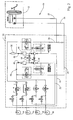
- FIGURE 1 is a schematic view of a first exemplary braking system in accordance with the invention in which a bypass line with a normally-closed electrically-operated valve interconnects the pressure relief lines of the unit's primary and secondary braking circuits;
- FIGURE 2 is a schematic view of a second exemplary braking system in accordance with the invention in which the circuit-shunting bypass line interconnects the braking circuits at a bypass location on each braking circuit that is upstream of the pressure relief line's damping chamber, with each pressure relief lines further including an additional check valve to enhance braking system redundancy;
- FIGURE 3 is a schematic view of a third exemplary braking system in accordance with the invention, in which the shunting bypass line couples the pressure relief lines of the two braking circuits upstream of each circuit's damping chamber, and wherein system redundancy is provided by a check valve in the secondary circuit downstream of the damping chamber orifice;
- FIGURE 4 is a schematic view of the fourth exemplary braking system in accordance with the invention, in which the shunting bypass line couples the pressure relief lines up to braking circuits downstream of each circuit's damping chamber orifice, and wherein system redundancy is provided by use of a second normally-closed valve in the bypass line; and
- FIGURE 5 is a view in cross-section of a normally-open electrically-operated valve suitable for use in the bypass line of the fourth exemplary braking system of Figure 4.
- a first exemplary hydraulic braking system 10 in accordance with the invention controls the flow of pressurized brake fluid from a brake actuation unit 12, such as a pedal-operated tandem master cylinder 14 that includes a vacuum brake booster by which to amplify the applied pedal force, to several wheel brakes 16 via a pair of braking circuits 18,20 conveniently housed within a hydraulic control unit 22.
- a brake actuation unit 12 such as a pedal-operated tandem master cylinder 14 that includes a vacuum brake booster by which to amplify the applied pedal force, to several wheel brakes 16 via a pair of braking circuits 18,20 conveniently housed within a hydraulic control unit 22.
- each braking circuit 18,20 features a brake line 24 that receives pressurized fluid from the master cylinder 14 through a pulsation damper 26.
- Each brake line 24 includes a normally-open electrically-operated isolation valve 28 whose operation is controlled by a system controller (not shown).
- Each brake line 24 is also selectively connected to each of a pair of wheel brakes 16 through a dedicated normally-open electrically-operated inlet valve 30, also operated by the system controller, to achieve anti-lock vehicle braking, vehicle traction control, and/or vehicle electronic stability control.
- each braking circuit 18,20 of the first braking system 10 also features a pressure relief line 32 that selectively receives pressurized fluid from each of the braking circuit's wheel brakes 16 through a respective, dedicated normally-closed electrically-operated outlet valve 34, similarly under microprocessor control.
- the pressure relief line 32 is connected to the brake line 24 between the isolation valve 28 and the wheel brake inlet valves 30, and further typically includes a reservoir or low-pressure accumulator 36, a pump 38 having an outlet 40, and a check valve 42 for preventing reverse fluid flow through the pump 38.
- Each pressure relief line 32 also includes a damping chamber 44 and a throttling orifice 46, each located downstream of the pump outlet 40, which operate to smooth fluid pressure spikes in the brake line 24.
- a normally-closed electronic shuttle valve 48 controls the flow of brake fluid from the brake line 24 upstream of the isolation valve 28 to the suction side of the pump 38.
- the first braking system 10 further includes a bypass line 50 interconnecting the pressure relief lines 32 of the first and second braking circuits 18,20 at a respective bypass location 52,54 on each braking circuit 18,20 downstream of the pump outlet 40.
- the bypass line 50 includes a normally-closed electrically-operated bypass valve 56.
- the controller opens the bypass valve 56, the pump output of one braking circuit (for example, the first braking circuit 18) is allowed to flow through the bypass line 50 to augment the pump output of the other braking circuit (for example, the second braking circuit 20) and, hence, reduce system response time when, for example, one or more wheel brakes 16 of the other braking circuit (here, the second braking circuit 20) are actuated to enhance vehicle traction or stability.
- the first braking system 10 further includes a pressure transducer 58 coupled to each braking circuit 18,20 at a location on the respective braking circuit 18,20 downstream of the isolation valve 28, and between the pump outlet 40 and the inlet valves 30.
- the pressure transducer 58 is located in the pressure relief line 32 downstream of the damping chamber 44 and throttling orifice 46, each of which serves to "smooth" pressure spikes that may be generated at the pump outlet 40.
- the pressure transducers 58 detect the fluid pressure achieved at the respective locations on the braking circuits 18,20, preferably after the controller has deenergized the bypass valve 56 to thereby return the bypass valve 56 to a closed condition, to facilitate identification by the controller of any instance of bypass valve leakage.
- such fluid pressure monitoring within each of the braking circuits 18,20 facilitates avoidance of unnecessarily high pressure in the hydraulic control unit 22 and, hence, is useful in improving the durability of the first braking system 10.
- the controller determines that additional fluid flow in one or the other braking circuits 18,20 is desirable, for example, when the controller determines that an actuation of one or more wheel brakes 16 is desirable to enhance vehicle traction or stability control
- the controller closes the isolation valves 28 and then opens the bypass valve 56 to interconnect the two braking circuits 18,20 at the respective bypass locations 52,54.
- the pump output from one braking circuit 18,20 is allowed to flow into the other braking circuit 18,20 to rapidly build up fluid pressure at one or two specific wheel brakes 16.
- the pump flow delivered to the selected wheel brakes 16 during interconnection of the braking circuits 18,20 will be twice that of an isolated braking circuit 18,20.
- such interconnection of the two braking circuits 18,20 during a traction control mode advantageously serves to reduce pump-generated pressure spikes in the brake lines 24, thereby improving braking system noise, vibration and harshness (NVH) levels.
- a second exemplary braking system 60 includes a pair of braking systems 18,20, the pressure relief lines 32 of which are interconnected by a bypass line 50 at a respective bypass location 62,64 on each braking circuit 18,20 immediately downstream of the pump outlet 40, and upstream of the damping chamber 44 and throttling orifice 46.
- a normally-closed bypass valve 56 is disposed in the bypass line 50 to allow the controller to selectively interconnect the pressure relief lines 32 of the two braking circuits 18,20 to thereby provide rapid fluid pressure build-up and increased fluid flow in a selected braking circuit 18,20.
- a pressure transducer 58 senses the fluid pressure achieved in the first braking circuit 18 upon closure of the bypass valve 56, while a check valve 66 is disposed in the second braking circuit 20 operates to ensure continued functionality of the second braking circuit 20, notwithstanding a leakage of fluid through a "closed" bypass valve 56.
- the check valve 66 is placed on the pressure relief line 32 of the second circuit 20, downstream of the throttling orifice 46.
- a third exemplary braking system 68 similar to that of Figure 2, includes a pair of braking systems 18,20, the pressure relief lines 32 of which are likewise interconnected by a bypass line 50 at a respective bypass location 62,64 on each braking circuit 18,20 immediately downstream of the pump outlet 40, and upstream of the damping chamber 44 and throttling orifice 46.
- a normally-closed bypass valve 56 is disposed in the bypass line 50 to allow the controller to selectively interconnect the pressure relief lines 32 of the two braking circuits 18,20 to thereby provide rapid fluid pressure build-up and increased fluid flow in a selected braking circuit 18,20.
- the third braking system 68 of Figure 3 utilizes a pair of check valves 70 disposed in the respective pressure relief line 32 of each braking circuit 18,20 immediately downstream of the bypass locations 62,64. As with the check valve 66 of the second braking circuit 60, the check valves 70 of the third braking system 68 operate to ensure continued functionality of the second braking circuit 20, notwithstanding a leakage of fluid through a "closed" bypass valve 56.
- a fourth exemplary braking system 72 is illustrated in Figure 4.
- the fourth braking system 72 includes a pair of braking systems 18,20 whose pressure relief lines 32 are interconnected by a bypass line 50 at a respective bypass location 52,54 on each braking circuit 18,20 downstream of the pump outlet 40, the damping chamber 44, and the throttling orifice 46.
- a normally-closed bypass valve 56 in the bypass line 50 allows the controller to selectively interconnect the pressure relief lines 32 to thereby provide rapid fluid pressure build-up and increased fluid flow in a selected braking circuit 18,20.
- the bypass line 50 of the fourth braking system 72 includes a second normally-closed electrically-operated bypass valve 74 connected in series with the first bypass valve 56.
- each of the bypass valves 56,74 of the fourth braking system 72 features a valve element that is hydraulically biased to a sealing position when a fluid pressure achieved at the bypass location 52,54 on one braking circuit 18,20 is greater than a fluid pressure achieved at the bypass location 52,54 on the other braking circuit 18,20.
- An exemplary bypass valve 56,74 for use with the fourth braking system is illustrated in Figure 5.
- each of the disclosed braking systems 10,60,68,72 conveniently house the several components of both primary and secondary braking circuits 18,20, as well as those of the bypass line 50, within a hydraulic control unit 22, the invention contemplates any suitable packaging of the braking system's several components, including definition of the bypass line 50 externally of a housing that otherwise defines the system's primary and secondary circuits 18,20.
- the disclosed braking systems 10,60,68,72 each employ a tandem master cylinder 14 as the brake actuation unit 12, the invention contemplates any suitable driver-actuated fluid pressure generator, including suitable "brake-by-wire" systems, with which to generate a pair of pressurized fluid outputs in response to a braking signal.
Applications Claiming Priority (2)
| Application Number | Priority Date | Filing Date | Title |
|---|---|---|---|
| US418376 | 1989-10-06 | ||
| US10/418,376 US6896338B2 (en) | 2003-04-18 | 2003-04-18 | Hydraulic braking system featuring selectable increased pump flow |
Publications (2)
| Publication Number | Publication Date |
|---|---|
| EP1468888A2 true EP1468888A2 (de) | 2004-10-20 |
| EP1468888A3 EP1468888A3 (de) | 2005-07-27 |
Family
ID=32908353
Family Applications (1)
| Application Number | Title | Priority Date | Filing Date |
|---|---|---|---|
| EP04008916A Withdrawn EP1468888A3 (de) | 2003-04-18 | 2004-04-15 | Hydraulisches Bremssystem mit steuerbarem erhöhten Pumpenstrom |
Country Status (3)
| Country | Link |
|---|---|
| US (1) | US6896338B2 (de) |
| EP (1) | EP1468888A3 (de) |
| JP (1) | JP4739687B2 (de) |
Cited By (1)
| Publication number | Priority date | Publication date | Assignee | Title |
|---|---|---|---|---|
| WO2014099747A1 (en) * | 2012-12-19 | 2014-06-26 | Robert Bosch Gmbh | Braking system with switchable pump path |
Families Citing this family (14)
| Publication number | Priority date | Publication date | Assignee | Title |
|---|---|---|---|---|
| US7325883B2 (en) * | 2004-10-04 | 2008-02-05 | Continental Teves, Inc. | Hydraulic braking system featuring selectively-coupled pump suction circuits |
| JP4492320B2 (ja) * | 2004-11-30 | 2010-06-30 | トヨタ自動車株式会社 | 異常検出装置 |
| US7712845B2 (en) * | 2006-05-18 | 2010-05-11 | Gm Global Technology Operations, Inc. | Method to reduce the turn radius of motor vehicles utilizing automatic single side rear brake application |
| DE102007016250A1 (de) * | 2006-12-12 | 2008-06-19 | Robert Bosch Gmbh | Scheibenbremse |
| DE102008040326A1 (de) * | 2008-07-10 | 2010-01-14 | Deere & Company, Moline | Lenkbremseinrichtung für ein Kraftfahrzeug |
| US8075066B2 (en) | 2009-04-02 | 2011-12-13 | GM Global Technology Operations LLC | Metering check valve for active brake pads retraction system |
| DE102009045714A1 (de) * | 2009-04-28 | 2010-11-04 | Continental Teves Ag & Co. Ohg | Schlupfgeregelte hydraulische Fahrzeugbremsanlage |
| US9463780B2 (en) | 2013-05-21 | 2016-10-11 | Robert Bosch Gmbh | Brake system and method of operating |
| US9399976B2 (en) * | 2013-07-18 | 2016-07-26 | Denso International America, Inc. | Fuel delivery system containing high pressure pump with isolation valves |
| US11760329B2 (en) * | 2015-03-16 | 2023-09-19 | Ipgate Ag | Brake system with a new type of MUX control (MUX 2.0), having an outlet valve per brake system or an outlet valve per brake circuit, and method for controlling pressure |
| US10620078B2 (en) | 2017-11-17 | 2020-04-14 | Robert Bosch Gmbh | Performing a diagnostic on a hydraulic system while the vehicle is operating |
| JP2019116155A (ja) * | 2017-12-27 | 2019-07-18 | ロベルト・ボッシュ・ゲゼルシャフト・ミト・ベシュレンクテル・ハフツングRobert Bosch Gmbh | ブレーキ液圧制御装置 |
| US10538226B1 (en) * | 2018-07-06 | 2020-01-21 | Starsky Robotics, Inc. | Vehicle braking system and method |
| GB2602157A (en) * | 2020-12-21 | 2022-06-22 | Airbus Operations Ltd | Braking system |
Citations (3)
| Publication number | Priority date | Publication date | Assignee | Title |
|---|---|---|---|---|
| DE4445360A1 (de) * | 1994-12-20 | 1996-06-27 | Bosch Gmbh Robert | Hydraulische Zweikreis-Fahrzeugbremsanlage |
| DE19835250A1 (de) * | 1997-08-04 | 1999-02-11 | Nisshin Spinning | Hydraulikbremskreis für Kraftfahrzeuge |
| DE10025038A1 (de) * | 2000-05-20 | 2001-11-29 | Daimler Chrysler Ag | Verfahren und Vorrichtung zur verbesserten Druckdynamik bei aktivem Druckaufbau in einer Fahrzeugbremsanlage |
Family Cites Families (2)
| Publication number | Priority date | Publication date | Assignee | Title |
|---|---|---|---|---|
| US4824183A (en) * | 1987-04-21 | 1989-04-25 | Toyota Jidosha Kabushiki Kaisha | Dual-circuit hydraulic anti-lock braking system |
| US5540488A (en) * | 1995-05-11 | 1996-07-30 | Aisin Seiki Kabushiki Kaisha | Hydraulic braking system having an auxiliary pressure source |
-
2003
- 2003-04-18 US US10/418,376 patent/US6896338B2/en not_active Expired - Lifetime
-
2004
- 2004-04-15 EP EP04008916A patent/EP1468888A3/de not_active Withdrawn
- 2004-04-19 JP JP2004122764A patent/JP4739687B2/ja not_active Expired - Fee Related
Patent Citations (3)
| Publication number | Priority date | Publication date | Assignee | Title |
|---|---|---|---|---|
| DE4445360A1 (de) * | 1994-12-20 | 1996-06-27 | Bosch Gmbh Robert | Hydraulische Zweikreis-Fahrzeugbremsanlage |
| DE19835250A1 (de) * | 1997-08-04 | 1999-02-11 | Nisshin Spinning | Hydraulikbremskreis für Kraftfahrzeuge |
| DE10025038A1 (de) * | 2000-05-20 | 2001-11-29 | Daimler Chrysler Ag | Verfahren und Vorrichtung zur verbesserten Druckdynamik bei aktivem Druckaufbau in einer Fahrzeugbremsanlage |
Cited By (2)
| Publication number | Priority date | Publication date | Assignee | Title |
|---|---|---|---|---|
| WO2014099747A1 (en) * | 2012-12-19 | 2014-06-26 | Robert Bosch Gmbh | Braking system with switchable pump path |
| US9033426B2 (en) | 2012-12-19 | 2015-05-19 | Robert Bosch Gmbh | Braking system with switchable pump path |
Also Published As
| Publication number | Publication date |
|---|---|
| EP1468888A3 (de) | 2005-07-27 |
| US6896338B2 (en) | 2005-05-24 |
| US20040207253A1 (en) | 2004-10-21 |
| JP4739687B2 (ja) | 2011-08-03 |
| JP2004314960A (ja) | 2004-11-11 |
Similar Documents
| Publication | Publication Date | Title |
|---|---|---|
| US6896338B2 (en) | Hydraulic braking system featuring selectable increased pump flow | |
| US5918948A (en) | Method of operating an anti-lock automotive vehicle brake system | |
| US4685747A (en) | Brake system with slip control | |
| JP3989956B2 (ja) | 電子制御可能なブレーキ操作装置 | |
| JP2718732B2 (ja) | アンチスキッド制御付き液圧ブレーキ装置 | |
| EP1334894B1 (de) | Elektronisch gesteuertes Bremssystem für Kraftfahrzeuge | |
| US8210619B2 (en) | Braking control system of two-wheeled motor vehicle | |
| US6142583A (en) | Anti-locking hydraulic motor vehicle brake system | |
| US9296369B2 (en) | Brake control system for motor vehicles, having an electronic control device | |
| US20090033146A1 (en) | Method and device for operating a hydraulic vehicle brake system | |
| US6120111A (en) | Brake hydraulic circuit for motor vehicles | |
| US20040075337A1 (en) | Method for controlling an electrohydraulic braking system | |
| JPS6334271A (ja) | 自動車のスリップ制御形ブレ−キ装置 | |
| US20080179944A1 (en) | Hydraulic anti-lock brake system | |
| JP2008515702A (ja) | モーターサイクルブレーキシステム | |
| US7537294B2 (en) | Vehicle braking system with active hydraulic brake force assistance and control method for the same | |
| EP1459950A1 (de) | Bremsdrucksteuervorrichtung in einer Bremsanlage | |
| JP3750242B2 (ja) | 車両用ブレーキ装置 | |
| US7325883B2 (en) | Hydraulic braking system featuring selectively-coupled pump suction circuits | |
| JP4543540B2 (ja) | 車両のブレーキ制御装置 | |
| US20050001473A1 (en) | Method for actuating an external-force parking brake system | |
| US6019439A (en) | Method of operating an anti-locking automotive vehicle-brake system | |
| JP3090491B2 (ja) | 車両のブレーキ液圧制御装置 | |
| JP3656388B2 (ja) | 車両挙動制御装置 | |
| US6120112A (en) | Brake pressure control device for vehicle |
Legal Events
| Date | Code | Title | Description |
|---|---|---|---|
| PUAI | Public reference made under article 153(3) epc to a published international application that has entered the european phase |
Free format text: ORIGINAL CODE: 0009012 |
|
| AK | Designated contracting states |
Kind code of ref document: A2 Designated state(s): AT BE BG CH CY CZ DE DK EE ES FI FR GB GR HU IE IT LI LU MC NL PL PT RO SE SI SK TR |
|
| AX | Request for extension of the european patent |
Extension state: AL HR LT LV MK |
|
| PUAL | Search report despatched |
Free format text: ORIGINAL CODE: 0009013 |
|
| RIC1 | Information provided on ipc code assigned before grant |
Ipc: 7B 60T 8/48 B Ipc: 7B 60T 8/42 B Ipc: 7B 60T 8/40 B Ipc: 7B 60T 8/34 A |
|
| AK | Designated contracting states |
Kind code of ref document: A3 Designated state(s): AT BE BG CH CY CZ DE DK EE ES FI FR GB GR HU IE IT LI LU MC NL PL PT RO SE SI SK TR |
|
| AX | Request for extension of the european patent |
Extension state: AL HR LT LV MK |
|
| 17P | Request for examination filed |
Effective date: 20060112 |
|
| AKX | Designation fees paid |
Designated state(s): DE FR |
|
| 17Q | First examination report despatched |
Effective date: 20070321 |
|
| STAA | Information on the status of an ep patent application or granted ep patent |
Free format text: STATUS: THE APPLICATION IS DEEMED TO BE WITHDRAWN |
|
| 18D | Application deemed to be withdrawn |
Effective date: 20071002 |