EP1467937B1 - Portique roulant a tampon - Google Patents
Portique roulant a tampon Download PDFInfo
- Publication number
- EP1467937B1 EP1467937B1 EP02794225A EP02794225A EP1467937B1 EP 1467937 B1 EP1467937 B1 EP 1467937B1 EP 02794225 A EP02794225 A EP 02794225A EP 02794225 A EP02794225 A EP 02794225A EP 1467937 B1 EP1467937 B1 EP 1467937B1
- Authority
- EP
- European Patent Office
- Prior art keywords
- crane
- containers
- container
- buffer
- landing deck
- Prior art date
- Legal status (The legal status is an assumption and is not a legal conclusion. Google has not performed a legal analysis and makes no representation as to the accuracy of the status listed.)
- Expired - Fee Related
Links
- 230000008021 deposition Effects 0.000 claims description 14
- 238000012546 transfer Methods 0.000 claims description 5
- 238000000034 method Methods 0.000 description 11
- 238000009434 installation Methods 0.000 description 9
- 230000001934 delay Effects 0.000 description 6
- 238000013461 design Methods 0.000 description 6
- 230000008569 process Effects 0.000 description 6
- 230000008901 benefit Effects 0.000 description 4
- 230000007246 mechanism Effects 0.000 description 4
- 230000000153 supplemental effect Effects 0.000 description 4
- 230000006378 damage Effects 0.000 description 3
- 230000003111 delayed effect Effects 0.000 description 3
- 239000000725 suspension Substances 0.000 description 3
- 229910000831 Steel Inorganic materials 0.000 description 2
- 208000027418 Wounds and injury Diseases 0.000 description 2
- 238000010276 construction Methods 0.000 description 2
- 230000006872 improvement Effects 0.000 description 2
- 208000014674 injury Diseases 0.000 description 2
- 230000004048 modification Effects 0.000 description 2
- 238000012986 modification Methods 0.000 description 2
- 230000035939 shock Effects 0.000 description 2
- 239000010959 steel Substances 0.000 description 2
- 230000001133 acceleration Effects 0.000 description 1
- 230000003466 anti-cipated effect Effects 0.000 description 1
- 238000005452 bending Methods 0.000 description 1
- 238000005266 casting Methods 0.000 description 1
- 238000004891 communication Methods 0.000 description 1
- 238000005137 deposition process Methods 0.000 description 1
- 238000010586 diagram Methods 0.000 description 1
- 230000000694 effects Effects 0.000 description 1
- 230000008030 elimination Effects 0.000 description 1
- 238000003379 elimination reaction Methods 0.000 description 1
- 238000007689 inspection Methods 0.000 description 1
- 238000011900 installation process Methods 0.000 description 1
- 230000001788 irregular Effects 0.000 description 1
- 230000003287 optical effect Effects 0.000 description 1
Images

Classifications
-
- B—PERFORMING OPERATIONS; TRANSPORTING
- B65—CONVEYING; PACKING; STORING; HANDLING THIN OR FILAMENTARY MATERIAL
- B65G—TRANSPORT OR STORAGE DEVICES, e.g. CONVEYORS FOR LOADING OR TIPPING, SHOP CONVEYOR SYSTEMS OR PNEUMATIC TUBE CONVEYORS
- B65G63/00—Transferring or trans-shipping at storage areas, railway yards or harbours or in opening mining cuts; Marshalling yard installations
- B65G63/002—Transferring or trans-shipping at storage areas, railway yards or harbours or in opening mining cuts; Marshalling yard installations for articles
- B65G63/004—Transferring or trans-shipping at storage areas, railway yards or harbours or in opening mining cuts; Marshalling yard installations for articles for containers
-
- B—PERFORMING OPERATIONS; TRANSPORTING
- B65—CONVEYING; PACKING; STORING; HANDLING THIN OR FILAMENTARY MATERIAL
- B65G—TRANSPORT OR STORAGE DEVICES, e.g. CONVEYORS FOR LOADING OR TIPPING, SHOP CONVEYOR SYSTEMS OR PNEUMATIC TUBE CONVEYORS
- B65G63/00—Transferring or trans-shipping at storage areas, railway yards or harbours or in opening mining cuts; Marshalling yard installations
-
- B—PERFORMING OPERATIONS; TRANSPORTING
- B63—SHIPS OR OTHER WATERBORNE VESSELS; RELATED EQUIPMENT
- B63B—SHIPS OR OTHER WATERBORNE VESSELS; EQUIPMENT FOR SHIPPING
- B63B27/00—Arrangement of ship-based loading or unloading equipment for cargo or passengers
-
- B—PERFORMING OPERATIONS; TRANSPORTING
- B66—HOISTING; LIFTING; HAULING
- B66C—CRANES; LOAD-ENGAGING ELEMENTS OR DEVICES FOR CRANES, CAPSTANS, WINCHES, OR TACKLES
- B66C19/00—Cranes comprising trolleys or crabs running on fixed or movable bridges or gantries
- B66C19/002—Container cranes
Definitions
- the present invention relates to a supplemental apparatus for cargo container handling gantry cranes and, more particularly, it relates to a device for improving the efficiency of the cycle time for dockside quay cranes. Specifically, it relates to a buffer crane which operates in conjunction with cargo container handling gantry cranes.
- FIG. 1 of the drawings shows a typical dockside berthing operation for a ship.
- the primary container handling equipment is comprised of one or more quay cranes 11 which extend outboard from the dock's edge 13 across the beam of a ship 15.
- Cargo containers 17 which have been unloaded or are to be loaded are temporarily stored in a stacking yard 19 proximate to the ship's loading berths.
- the berthing operations under specific consideration involve the transport of containers between a container ship and the stacking yard.
- quay cranes 11 access the shipboard cargo containers from above the ship and move them to the ground level or dockside cargo container transporters 21 such as chassis trucks, trailer trucks, or automatically guided vehicles (AGVs).
- the transporters deliver the containers to the stacking yard 19 where other vehicles or cranes 23 transfer the containers to stacks.
- quay cranes lift the cargo containers from the dockside container transporters and move them to the ship where they are lowered into shipboard cells.
- the berthing operations involve three separate types of sub-operations: (1) quay crane handling; (2) transport between the crane and the stacking yard; and (3) storage yard manipulation.
- Quay cranes in the form of cargo container handling gantry cranes are arranged to extend over a longitudinal expanse and transfer cargo containers horizontally from one deposition area to another.
- the largest of such gantry cranes are primarily located dockside in shipping ports around the world as well as in railroad yards.
- Quay cranes generally have either a horizontal sliding boom or a cantilever boom, the latter of which can usually be raised by rotating it around its inboard end.
- Long span yard and quay cranes are typically supported by vertical structures located inboard from the ends of the crane gantry on rail mounted wheels.
- the present invention can be utilized with any of these basic types of crane designs and operations.
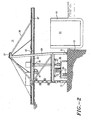
- FIG. 2 of the drawings illustrate a typical cantilever boom type quay crane 11 having a buffer crane 25 of the present invention positioned thereunder.
- the quay crane cantilevered rotatable boom 27 is supported by the crane superstructure 29 mounted on crane truck wheels 31 which run on dock rails which are disposed parallel to the edge 13 of the harbor dock.
- the crane superstructure supports a horizontal gantry 33 disposed generally mid-height thereon at an elevated location above the cargo container pickup and deposition areas 35.
- the gantry is supported from below by the main legs of the superstructure.
- sheaves are disposed at the pinnacle 37 of the superstructure of the crane to guide wire rope reeving 39 which is used to lift the outboard or cantilevered end of the boom to the upright raised stowed position.
- the wire rope reeving raises the cantilevered boom by rotating it about its hinge point 43 at its inboard end proximate to the superstructure.
- the gantry of a cargo container handling quay crane is a slidable or a raisable cantilevered boom extending from a crane superstructure to project over a ship
- other types of large gantry yard cranes supported at both ends are located in large cargo container storage or transfer areas. All of these cranes are similar to the gantry type crane of FIG. 2 in that they employ a movable trolley 45, usually with a suspended operator's cab 47, which shuttles along the gantry 33 and boom 27 suspending a cargo container lifting spreader 49.
- the spreader can be raised or lowered from the crane gantry by the operator and engages from above the top of cargo containers 17.
- the containers are carried by a transporter 21 or are stacked on the dock or shipboard to permit them to be lifted by the trolley for horizontal transport.
- the containers are lifted from the transporter and are moved outboard along the gantry to where they are lowered into the cells 51 in a cargo container transport ship.
- the containers are lifted from the cells and moved from shipboard to shore where they are lowered onto the transporters.
- the cargo container lift trolley 45 mounted on rails on the crane gantry sections 27, 33, can traverse from one end of the gantry to the other with a suspended container.
- the cargo container lifting spreader 49 is suspended from the trolley by fleet through wire rope reeving through a detachable headblock which carries the wire rope suspension sheaves. Different or variable length spreaders can be secured to the headblock to accommodate correspondingly different size containers.
- berthing sub-operations There are two highly interdependent berthing sub-operations: (1) quay crane handling; and (2) transport vehicle movements between the crane and the stacking yard. A delay in one of those sub-operations causes the other to pause and idle which reduces the overall productivity of the entire system.
- IBC interbox connector
- Quay crane container handling rates are measured in cycle rates. Unsteady quay crane operations result because the cranes move containers different distances depending upon the location of the container on a ship varying the cycle rates. For example, as a quay crane loads or unloads each column of containers spaced across the beam of the ship, the hoist travels a longer distance outboard for each successive column of containers and lowers and hoists longer for each container located deeper in the stack. The increased traveling distance and stationary time for the hoist, for each successive container, adds to the container handling time and the resulting cycle time.
- Unsteady quay crane operation coupled with a constant number of transport vehicles allotted per crane, creates inefficiencies in the overall operation.
- transport vehicles When quay crane handling rates or cycle time are slow, transport vehicles must wait. In those instances where the quay crane handles containers fast and cycle time is short, and if the number of transport vehicles is insufficient for the cycle time, the quay crane must wait.
- IBC interbox connector
- the interbox connector (IBC) installation and removal processes cause both quay cranes and transport vehicles to idle.
- IBCs are cone-shaped devices that lock stacked containers together on the ship. When quay cranes lift containers from the ship, the IBCs are still attached to the bottom of the container. Usually, the quay cranes must lower the container until it is a few feet above the port terminal dock level where a worker crew can reach underneath and remove the IBCs.
- the installation processes are just the reverse.
- the IBC operations cause a significant amount of quay crane and transport vehicle idle time to be induced into the system cycle time as well as exposing the workers to the possibility of injury from a swaying or dropped container or any other hazards associated with proximity to a lifted load and to continuous transport vehicle operations.
- Delays in stacking yard operations also cause delays in the throughput of container transport vehicles.
- the vehicles load or unload containers at the stacking yard before returning to the cranes.
- Disruptions in the flow of transport vehicles to and from the quay crane loading area are caused by numerous factors such as driver inexperience and lack of familiarity with the apparatus and layout of the yard, as well as yard worker inexperience, which cause the delays in the stacking yard operations. If the disruptions are sufficiently severe, then the quay cranes must wait in idle for a transport vehicle to return.
- the buffer crane operations contemplated according to the present invention departs substantially from the conventional concepts, designs, and modes of quay crane operation taught by the prior art. In doing so, the present invention provides an apparatus primarily developed for the purpose of improving the overall efficiency of berthing operations by reducing or eliminating the delay problems described above. It accomplishes the result in a different and improved manner for the dockside handling of cargo containers.
- the buffer crane of the present invention functions mainly by establishing a temporary storage or holding operation between the quay cranes and the transport vehicles which reduces the interdependence therebetween.
- the buffer operation in effect constitutes a container reservoir between two of the three berthing sub-operations: quay crane handling and transport between the crane and the stacking yards.
- the temporary storage reservoir permits the quay crane to take or deposit containers even if no transporter is available, or conversely, for a transporter to extract a container, or deposit one in the reservoir.
- the other sub-operation continues to work with the buffer operation while the delayed sub-operation resolves its problem.
- the present invention provides a new crane construction wherein the same can be utilized to improve the efficiency of cargo container ship berthing operations.
- the general purpose of the present invention is to provide a new crane apparatus and function which has all of the advantages of the prior art mentioned above, as well as many novel features that result in new methods of berthing operations, which are not anticipated, rendered obvious, suggested, or even implied by any of the prior art of quay cranes and port berthing operations either alone or in any combination thereof.
- the present invention is a buffer straddle crane for cargo container handling. It is comprised of an elevated platform forming a landing deck where containers can be landed and temporarily stored by a quay crane when they are removed from shipboard or where containers picked off ground level transporters can be landed until they are picked up by the quay crane for transport to a ship.
- the platform has an opening in the landing deck where containers can be lowered and raised therethrough.
- the buffer crane platform is supported by motorized transport wheels for independent all-direction movement. It has a low profile whereby it can be positioned underneath the quay crane to receive cargo containers therefrom as well as from container transporters.
- the quay crane can extract containers therefrom and the buffer crane can deliver containers therefrom to the container transporters.
- the platform supports a cargo container handling straddle crane mounted on rails disposed on the fore and aft edges of the platform and has cargo container lifting apparatus arranged to transfer containers between the landing deck and cargo container transporters parked or located underneath the platform through the opening in the landing deck.
- FIGS. 2 and 3 of the drawings show the quay crane 11 and a buffer straddle crane 25 which are located dockside in a shipping port.
- the buffer crane is low profile so that it can be positioned underneath a quay crane during container handling operations. It is contemplated that a buffer crane could also be utilized in a railroad stacking yard as well as dockside under a large bridge or straddle crane, so the term "quay crane" as used in the claims is intended to include these types of cranes also.
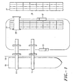
- FIG. 3 shows the buffer straddle crane in operation. It is essentially a landing deck where containers can be landed by a quay crane when they are removed from shipboard and temporarily stored or where containers picked off ground level transporters can be landed until they are picked up by the quay crane for transport to a ship.
- the buffer straddle crane is a gantry frame forming a raised or elevated upper platform 53 with a multiple of subplatforms 55.
- the buffer crane sits under a quay crane and interposes a container reservoir between the quay crane and the container transport vehicles.
- the quay crane can take or extract containers therefrom and the buffer crane can deliver containers therefrom to the transporters. It creates a new and additional sub-operation in ship berthing operations which reduces quay crane cycle time in cargo container handling.
- the quay crane 11 deposits or retrieves containers 17 onto or from the upper platform of the buffer crane called the landing deck 53.
- the subplatforms 55 disposed slightly below the landing deck are working areas for port operators called service decks.
- the landing deck can support multiple containers to function as the container reservoir or pool in the buffer operation.
- Container transport vehicles 21, such as chassis trucks, trailer trucks, or AGVs, drive under or below the raised platform to either deliver or receive containers to and from the buffer crane landing deck.
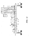
- a dedicated cargo container handling crane in the form of an overhead rail mounted straddle crane 57 disposed above the landing deck 53 moves the containers 17 between the transport vehicles 21 and the landing deck.
- the straddle crane is mounted on rails 59 on the landing deck and supports cargo container handling apparatus above the landing deck by legs 61 disposed at the fore and aft edges thereof.
- the straddle crane drops containers onto and retrieves them from dockside container transporters through one or more openings in the landing deck.
- Port operators can also perform certain tasks on the containers from the safety of the service decks 55 while the containers rest on the landing deck 53.
- the service decks are provided with rigid shelters 63 to protect service workers from descending containers and inclement weather.
- both the quay cranes and transport vehicles must sit idle while the IBCs are installed or removed.
- the buffer crane system allows port operators to perform IBC installation and removal operations while the containers rest in the buffer pool on the landing deck so that neither the quay crane nor the container transport systems need to idle during the IBC attachment or removal process.
- service personnel can verify container identification, re-mark a container, or perform minor container servicing while it resides on the landing deck.
- the upper platform or landing deck 53 has fore and aft and lateral edges 65.
- the landing deck 53 is supported at the corners thereof by four vertical support columns or legs 67.
- the platforms are supported on pneumatic transport wheels 69 for independent movement of the buffer crane 25.
- the rigid structure provides structural support for the loads from the straddle crane 57, for the buffer containers 17 deposited on the landing deck 53, and for emergency impact situations and accidental occurrences. Shock absorbing mechanisms diminish the force of the continuous impacts which result from the container landing operations as well as impacts which occur in emergency situations.
- the inflated rubber tires augment the shock absorbing mechanisms.
- the transport wheels 69 are secured to the legs 67 with a gantry drive for independent movement of the buffer crane 25 underneath the quay crane 11 and along dockside 13.
- the crane is mounted on tires so that it can operate without tracks or rails and can turn. Since the quay cranes move along the dock as they unload each successive row of container cells along the length of the ship, the buffer crane must likewise move along the dock to remain positioned under the quay crane.
- the buffer crane gantry drive is the arrangement of wheels, gear systems, drive motors, and brakes that allow the entire buffer crane system to move. By varying the speed of the tires, the crane can move in all directions and is omni-directional.
- the wheels are aligned parallel to the edge of the dock which allows the gantry frame of the buffer crane to move in the same direction as the quay crane.
- the buffer crane performs small turns by varying the wheel speeds on each side the crane.
- the landing deck 53 of the buffer crane stores containers 17 temporarily as a container reservoir or pool thereby functioning as the essential buffer platform.
- the landing deck is provided with at least one predetermined landing position formed on the landing deck and has support members 71 formed to receive and support containers which are lowered onto the landing position.
- a multiple of predetermined landing positions are dispersed over the landing deck, each with its set of support members.
- predetermined means that they are specifically located for automatic control of the crane operation. Generally between two and five parallel landing positions will suffice for the intended purpose of providing a container reservoir or pool.
- the straddle crane has container lifting apparatus 83 arranged to move containers between the landing deck and the transporters located underneath the platform through one or more openings in the landing deck.
- the landing deck is provided with at least one opening through which containers can be lowered or raised onto or from transporters which have been driven and positioned under the buffer crane.
- Guides 73 forming a chute are positioned on the sides of the opening to stop the sway of a suspended container being lowered therethrough. Similar guides can be positioned on the lower side of the landing deck for the related purpose: to stop the sway of a load being raised therethrough.
- Each container landing position can be located over an opening through which containers may be raised or lowered by making the support members 71 retractable laterally when a container is raised therefrom to allow the container to be dropped or raised through the opening in the landing deck.
- Retractable guides 73 can be moved into position concurrently or sequentially to stop any sway in the suspended container prior to deposition onto a landing position.
- the landing deck 53 is wide enough to accommodate several containers 17 in the predetermined landing positions. Access to the bottom of the containers deposited on the landing deck is provided by the service decks 55 on the landing deck disposed on both sides of the predetermined positions. When the containers are mounted on the support members 71, the sides and corners of the containers are exposed adjacent to the service decks. Equipment may be mounted on the service decks depending upon whether the IBC installation and removal operations are manual or automated.
- the service deck shelters protect service personnel who work partially below the landing deck from exposure to injury as well as the sun and rain.
- Similar sway arrest guides to those used around openings in the landing deck may be used to vertically guide the containers into place during landing on the deck to simplify and expedite the placement of the containers thereon.
- the bottom edges of the containers engage the guides which stop residual container sway of the suspended load and laterally displace the container into proper alignment onto the respective deposition position.
- the descending container slides downward along the guides in the vertical direction. Therefore, the container landing process requires less precision than current methods utilized with container transport vehicles. This saves considerable time by reducing container positioning requirements. It also reduces the work demand on the quay crane operators who currently endure fatiguing conditions.
- the guides also place the containers in specific locations so that the straddle crane may accurately move to the predetermined deposition and pick-up positions above the landing deck by automated control.
- the rail mounted straddle crane 57 is shown in closer detail in FIGS. 3 and 4. It has fore and aft legs 61 supporting a bridge 75 which suspends the container lifting apparatus above the landing deck 53. The lower ends of the legs are mounted on motor driven wheel carriages 77 engaged with the platform rails 59 for reciprocating lateral motion of the bridge along the width of the landing deck.
- the bridge spans the length of the landing deck and the openings therein whereby containers can be moved laterally along the landing deck to and from all of the openings therein. By this means, containers can be transferred through the landing deck between it and the container transporters parked underneath the buffer crane.
- the straddle crane has support legs long enough to permit the cargo container lifting apparatus suspended under the bridge, with a container suspended therefrom, to pass above cargo containers deposited on the buffer platform but with the top of the straddle crane disposed at a level below the supporting structure of any cargo container quay crane it is positioned under.
- each container deposition position is provided with an opening to allow containers to be dropped through the landing deck whereby the legs can be shortened.
- the cargo container lifting apparatus operates by reeling in and paying out rope from the suspension block that suspends the lifting spreader 49 whereby the apparatus is considered rope driven.
- the lifting spreaders are mechanisms that engage and hold containers while they are being lifted. Each corner of the spreader has a twist lock to lock onto the container at the corner castings thereof.
- the lifting spreader can be controlled by the crane operator to reciprocate in the length of its engagement to a container to accommodate different size containers in the lengths of 20 feet, 40 feet, 45 feet, and two containers of 20 feet each, linked end-to-end.
- the cargo container lifting apparatus also has the ability to perform incremental adjustments of the container's position to facilitate alignment with the transport vehicles 21.
- the apparatus accomplishes this result by giving and taking varying amounts of slack in the suspension ropes. In this manner, the apparatus can skew, list, and trim the container, as well as move the container laterally and longitudinally.
- the lifting apparatus therefore can quickly position containers on transport vehicles thereby eliminating the time-consuming task from the quay crane's cycle time.
- the buffer crane 25 includes an automated control system for partial operation of the straddle crane 57 to position the cargo container lifting apparatus over preselected positions on the landing deck 53 and to move containers 17 with coordinated motion to reduce sway in the suspended load.
- the straddle crane moves automatically between predetermined positions above the landing deck to general positions above the various transport vehicles 21.
- the crane operator only needs to select from the alternative predetermined container deposition positions on the landing deck to perform container engagement and pickup from a position and for container deposition at a selected position.
- Computer control performs precision alignment of the cargo containers with respect to the landing deck positions and general positioning of the container lifting spreader above the container transporters.
- the buffer crane operator controls the straddle crane for accurate alignment of the lifting spreader with the transport vehicle for container pickup or deposition.
- Computer software automatically controls the acceleration and movement of the straddle crane along the platform rails to insure that the movement is smooth and linear during both operator and automatic control of the crane drive and lift mechanisms.
- both the quay cranes and transport vehicles must sit idle while the IBCs are installed or removed.
- the quay cranes 11 must pause and hold the containers 17 a few feet off the ground so that personnel can manually install or remove the IBCs.
- the proximity of the personnel to the lifted container is also a safety hazard.
- the service decks 55 of the present invention are provided alongside the container landing positions on the landing deck 53. The situation may require a multiple of lowered service decks disposed between the container deposition positions on the landing deck for the service workers to operate from.
- the service decks or work platforms 55 are disposed at a level below the landing deck 53 surface to provide space for IBC attachment and removal operation.
- the design arrangement permits service workers to work standing up rather than intermittently or constantly bending over. Because the height limitations for the straddle crane design are restricted, and because of the possible need to lower containers through each predetermined landing position, the service deck cannot in every case be located directly below the landing deck.
- the service decks are in essence covered steel trenches, between the landing positions, from which the service workers can access the interbox connectors when a container is disposed on the support members 71 of an adjacent landing position.
- the service deck provision allows the safe and efficient installation and removal of the IBCs. It provides port operators with a work area within which to remove the IBCs from the cargo containers deposited on the landing deck either by hand or with IBC removal machinery. Machines or robotics can be provided to aid IBC installation and removal operations for further reducing the strain and danger for worker personnel and increasing the speed of quay crane operations. As a result, the quay cranes and transport vehicles do not need to idle or wait while the IBC installation or removal process occurs.
- the buffer crane operator driver works in an operators' cabin 85. It contains all of the automotive and the straddle crane 57 controls. Logistics are included to help the operator communicate with the quay crane operator and the service deck workers. Since the operator must communicate with so many individuals, it is essential that communication be clear and simplified to insure safety and productivity. Signal lights on the landing deck automatically indicate to the quay crane driver which containers are to be loaded onto the ship or have already been unloaded. There are indicator lights controlled by the service workers which tell the buffer crane operator whether the IBCs have been removed or not so that the operator does not prematurely move the container.
- the operator cabin provides simplified controls for the crane driver by reason of the computer controlled positioning of the straddle crane at the predetermined deposition positions on the landing deck.
- a diesel engine which is coupled to an alternator provides power to the buffer crane system, or it may be provided by electric cables.
- Weather protected steel enclosures protect the diesel engine and alternator couple from wear and possible damage.
- an electronic system automatically aligns the buffer crane with the quay crane along the cargo container transporter traffic lanes.
- the system can be comprised of optical, radio, or ultrasonic devices to measure the distance and relative position of the buffer crane to the quay crane.
- Information is linked to the quay drive system electronically which repositions the buffer crane until it is in the correct position directly below the quay crane trolley track and parallel to the quay crane quay wheels.
- Another electronic system insures that there is no interference or collision between the quay crane spreaders. With two devices accessing the landing deck, the quay crane and straddle crane, there is potential for interference and collision. The electronic system will identify the position of the quay crane lifting spreader to ensure that this does not occur.
- the buffer crane system has features that improve productivity and safety of port operations.
- the buffer crane is a stand-alone machine. It can operate with any existing quay cranes.
- the quay cranes require only minimal modification to accommodate the electronic linking systems. There are no costs involved which would be due to required extensive crane modifications or crane downtime. Because the buffer crane travels on rubber tires, the buffer operation does not require tracks, so there is no need to install additional rails on the port surface.
- the buffer crane has the advantage that is easy and inexpensive to install and can be applied to many cargo container handling ports in operation today.
- the buffer crane therefore resolves many of the delay issues described earlier. Even when one of the sub-operations of quay crane handling or container dockside transport is delayed, the other sub-operation may continue by accessing the containers on the buffer platform. The delayed sub operation can address the delay, and the other crane continue its work.
- the complete elimination of IBC installation and removal operations from the quay crane cycle time provides a huge improvement in the efficiency of berthing operations.
- the buffer crane system improves productivity and efficiency of port operations by providing a buffer operation between the quay cranes and transport vehicles sub-operations.
- This buffer allows quay cranes and vehicles to operate independently so that delays in one sub operation do not slow the overall productivity.
- the buffer allows port operators to perform tasks on containers such as marking and inspection while they sit on the buffer platform rather than having the quay cranes and transport vehicles wait while those operations are performed.
Claims (7)
- Portique roulant à tampon (25) destiné à manipuler des conteneurs, comprenant :une plate-forme élevée (53) formant un pont de déchargement où des conteneurs (17) peuvent être déchargés et stockés temporairement par un portique maritime lorsqu'ils sont retirés d'un navire (51), ou bien, où des conteneurs enlevés de dispositifs de transport au niveau du sol (21) peuvent être déchargés jusqu'à ce qu'ils soient ramassés par le portique maritime pour le transport jusqu'à un navire, ladite plate-forme comportant au moins une ouverture dans ledit pont de déchargement à travers laquelle des conteneurs peuvent être abaissés et levés, ladite plate-forme étant supportée par des roues de transport motorisées (69) pour un mouvement indépendant dans toutes les directions, ledit portique à tampon ayant un profil bas de sorte qu'il peut être positionné en dessous dudit portique maritime pour recevoir des conteneurs en provenance de celui-ci ainsi qu'en provenance desdits dispositifs de transport de conteneurs et de sorte que ledit portique maritime peut en extraire les conteneurs et ledit portique à tampon peut distribuer des conteneurs de celui-ci auxdits dispositifs de transport, etun portique roulant de manipulation de conteneurs (57) monté sur des rails (59) disposés sur les bords avant et arrière de ladite plate-forme et comportant un appareil de levage de conteneurs (49) agencé pour transférer des conteneurs entre ledit pont de déchargement et lesdits dispositifs de transport positionnés en dessous de ladite plate-forme à travers ladite ouverture dans ledit pont de déchargement.
- Portique à tampon selon la revendication 1, dans lequel ledit portique roulant (57) comporte des pieds avant et arrière (61) supportant une passerelle qui suspend ledit appareil de levage de conteneurs au-dessus dudit pont de déchargement (53), les extrémités inférieures desdits pieds étant montées sur des chariots à roues motorisés en prise avec lesdits rails de plate-forme (59) pour un mouvement alternatif latéral de ladite passerelle sur la largeur dudit pont de déchargement et de ladite ouverture dans ladite plate-forme, ladite passerelle couvrant la longueur dudit pont de déchargement de sorte que des conteneurs (17) peuvent être déplacés latéralement le long dudit pont de déchargement jusqu'à et à partir de ladite ouverture dans celui-ci de sorte que des conteneurs peuvent être transférés à travers celle-ci entre des dispositifs de transport de conteneurs (21) stationnés en dessous dudit portique à tampon et dudit pont de déchargement.
- Portique à tampon selon la revendication 2, dans lequel ledit portique roulant (57) et ledit appareil de levage de conteneurs (49) avec un conteneur (17) suspendu à celui-ci sont agencés sur ladite plate-forme (53) à un niveau pour passer au-dessus de conteneurs déposés sur ledit pont de déchargement et restent en dessous de la structure de support de tout portique maritime de conteneurs sous lequel est positionné ledit portique roulant.
- Portique à tampon selon la revendication 1, comprenant une multiplicité de positions de dépôt de conteneur parallèles prédéterminées situées sur ledit pont de déchargement (53).
- Portique à tampon selon la revendication 4, comprenant au moins une plate-forme de maintenance (55) disposée à côté dudit pont de déchargement (53) pour permettre à du personnel d'installer et d'enlever des connecteurs inter-boîtiers de conteneurs (17) déposés sur lesdites positions de dépôt situées sur ledit pont de déchargement.
- Portique à tampon selon la revendication 5, comprenant des plate-formes de maintenance (55) disposées des deux côtés de chacune desdites positions de dépôt situées sur ledit pont de déchargement (53) pour permettre à du personnel de maintenance d'installer ou d'enlever des connecteurs inter-boîtiers fixés à des coins de conteneurs (17) déposés sur lesdites positions de réception à partir de leurs côtés.
- Portique à tampon selon la revendication 4, comprenant un système de commande automatisé pour un fonctionnement partiel dudit portique roulant (57) pour positionner ledit appareil de levage de conteneurs (49) sur lesdites positions présélectionnées sur ledit pont de déchargement (53) et pour déplacer des conteneurs (17) avec un mouvement coordonné.
Applications Claiming Priority (3)
| Application Number | Priority Date | Filing Date | Title |
|---|---|---|---|
| US10/020,320 US6652211B2 (en) | 2001-12-11 | 2001-12-11 | Buffer straddle crane for cargo container handling operations |
| US20320 | 2001-12-11 | ||
| PCT/US2002/039647 WO2003050023A1 (fr) | 2001-12-11 | 2002-12-11 | Portique roulant a tampon |
Publications (3)
| Publication Number | Publication Date |
|---|---|
| EP1467937A1 EP1467937A1 (fr) | 2004-10-20 |
| EP1467937A4 EP1467937A4 (fr) | 2005-03-09 |
| EP1467937B1 true EP1467937B1 (fr) | 2006-07-12 |
Family
ID=21797953
Family Applications (1)
| Application Number | Title | Priority Date | Filing Date |
|---|---|---|---|
| EP02794225A Expired - Fee Related EP1467937B1 (fr) | 2001-12-11 | 2002-12-11 | Portique roulant a tampon |
Country Status (8)
| Country | Link |
|---|---|
| US (1) | US6652211B2 (fr) |
| EP (1) | EP1467937B1 (fr) |
| JP (1) | JP4312055B2 (fr) |
| KR (1) | KR100970818B1 (fr) |
| AU (1) | AU2002359672A1 (fr) |
| DE (1) | DE60213132T2 (fr) |
| ES (1) | ES2268146T3 (fr) |
| WO (1) | WO2003050023A1 (fr) |
Families Citing this family (16)
| Publication number | Priority date | Publication date | Assignee | Title |
|---|---|---|---|---|
| US7317782B2 (en) * | 2003-01-31 | 2008-01-08 | Varian Medical Systems Technologies, Inc. | Radiation scanning of cargo conveyances at seaports and the like |
| US7677857B2 (en) * | 2003-08-12 | 2010-03-16 | Paceco Corp. | Mobile cargo container scanning buffer crane |
| US7762760B2 (en) * | 2004-06-24 | 2010-07-27 | Paceco Corp. | Method of operating a cargo container scanning crane |
| ITMI20041334A1 (it) * | 2004-07-02 | 2004-10-02 | Fata Group S P A | Sistema di magazzino automatizzato di grandi dimensioni per strutture portuali |
| US20080286074A1 (en) * | 2005-08-16 | 2008-11-20 | Sunrose Tecdesign Pte. Ltd. | Inter-Box Connector (Ibc) Storage and Handling System |
| CN100366525C (zh) * | 2005-12-14 | 2008-02-06 | 上海振华港口机械(集团)股份有限公司 | 岸边起重机和堆场起重机间低架桥式小车转接装卸系统 |
| CN101229883A (zh) * | 2008-01-24 | 2008-07-30 | 上海振华港口机械(集团)股份有限公司 | 集装箱码头装卸系统 |
| US20090317213A1 (en) * | 2008-06-21 | 2009-12-24 | Paceco Corp. | Buffer crane for facilitating simultaneous multiple cargo container handling |
| FI123447B (fi) | 2011-03-18 | 2013-05-15 | Cimcorp Oy | Siltarobottijärjestelmä ja menetelmä sen käyttämiseksi |
| KR101873288B1 (ko) | 2013-06-27 | 2018-07-03 | 코네크레인스 글로벌 코포레이션 | 이동식 크레인 |
| FI126525B (fi) | 2013-06-27 | 2017-01-31 | Konecranes Global Oy | Nosturi |
| US10745250B2 (en) | 2015-10-27 | 2020-08-18 | Vladimir NEVSIMAL-WEIDENHOFFER | STS multi-trolley portal gantry container crane |
| NL2017631B1 (nl) * | 2016-10-18 | 2018-04-26 | Hallcon B V | Container vang- en zeevast systeem |
| KR102273765B1 (ko) * | 2019-09-11 | 2021-07-07 | 부산항만공사 | 스마트 컨테이너 셔틀 및 물류 시스템 |
| CN110697436B (zh) * | 2019-10-16 | 2020-12-01 | 长沙理工大学 | 一种水平旋转的折叠臂输送机 |
| KR102473292B1 (ko) * | 2020-11-18 | 2022-12-02 | 부산항만공사 | 스마트 컨테이너 스테이션 |
Family Cites Families (6)
| Publication number | Priority date | Publication date | Assignee | Title |
|---|---|---|---|---|
| JPS5531777A (en) * | 1978-08-30 | 1980-03-06 | Hitachi Ltd | Material handling apparatus for containers |
| JPH01126387U (fr) * | 1988-02-23 | 1989-08-29 | ||
| JPH01294121A (ja) * | 1988-05-18 | 1989-11-28 | Mitsubishi Heavy Ind Ltd | コンテナ移載装置 |
| DE9214516U1 (fr) * | 1992-10-27 | 1992-12-17 | Keuro Maschinenbau Gmbh & Co Kg, 7590 Achern, De | |
| US5515982A (en) * | 1994-04-11 | 1996-05-14 | Paceco Corp. | Telescoping shuttle for a cargo container handling crane |
| DE10002915A1 (de) * | 2000-01-19 | 2001-08-02 | Mannesmann Ag | Umschlaganlage in einem See- oder Binnenhafen |
-
2001
- 2001-12-11 US US10/020,320 patent/US6652211B2/en not_active Expired - Lifetime
-
2002
- 2002-12-11 JP JP2003551053A patent/JP4312055B2/ja not_active Expired - Fee Related
- 2002-12-11 WO PCT/US2002/039647 patent/WO2003050023A1/fr active IP Right Grant
- 2002-12-11 ES ES02794225T patent/ES2268146T3/es not_active Expired - Lifetime
- 2002-12-11 DE DE60213132T patent/DE60213132T2/de not_active Expired - Lifetime
- 2002-12-11 EP EP02794225A patent/EP1467937B1/fr not_active Expired - Fee Related
- 2002-12-11 AU AU2002359672A patent/AU2002359672A1/en not_active Abandoned
- 2002-12-11 KR KR1020047008990A patent/KR100970818B1/ko not_active IP Right Cessation
Also Published As
| Publication number | Publication date |
|---|---|
| JP2005512917A (ja) | 2005-05-12 |
| AU2002359672A1 (en) | 2003-06-23 |
| US20030108405A1 (en) | 2003-06-12 |
| EP1467937A4 (fr) | 2005-03-09 |
| ES2268146T3 (es) | 2007-03-16 |
| DE60213132T2 (de) | 2007-02-08 |
| KR20040089087A (ko) | 2004-10-20 |
| WO2003050023A1 (fr) | 2003-06-19 |
| EP1467937A1 (fr) | 2004-10-20 |
| DE60213132D1 (de) | 2006-08-24 |
| JP4312055B2 (ja) | 2009-08-12 |
| US6652211B2 (en) | 2003-11-25 |
| KR100970818B1 (ko) | 2010-07-16 |
Similar Documents
| Publication | Publication Date | Title |
|---|---|---|
| US6602036B2 (en) | Buffer bridge crane for cargo container handling operations | |
| EP1467937B1 (fr) | Portique roulant a tampon | |
| US5538382A (en) | Variable level lifting platform for a cargo container handling crane | |
| US20020197135A1 (en) | Container transfer terminal system and method | |
| US7559429B1 (en) | Wire rope reeving system for twin lift cargo container handling | |
| US4858775A (en) | Personnel trolley and elevator platform for a cargo container handling gantry crane | |
| US5570986A (en) | Cargo container transfer system for cranes | |
| US6554557B1 (en) | Inter-box connector (IBC) installation and removal system | |
| US5515982A (en) | Telescoping shuttle for a cargo container handling crane | |
| US6685418B2 (en) | Buffer jib crane for cargo container handling operations | |
| EP1467938B1 (fr) | Procede d'exploitation d'un portique portuaire destine a la manutention de conteneurs maritimes | |
| CN113620172A (zh) | 一种货运空铁集装箱提升中转装置及其方法 | |
| CA2184558C (fr) | Couloir de guidage pour grues servant a la manutention de conteneurs | |
| JP2564666B2 (ja) | 船舶用重量物貨物搭載装置 | |
| US20090317213A1 (en) | Buffer crane for facilitating simultaneous multiple cargo container handling | |
| US6648571B1 (en) | Mobile handling apparatus for loading and unloading ships in docks | |
| WO2020049285A1 (fr) | Véhicule pour le stockage de couvercle de trappe | |
| EP0827934B1 (fr) | Canal de guidage pour grues à conteneurs | |
| KR960004057B1 (ko) | 전천후 부두 선적시스템 | |
| JPH05185984A (ja) | 車両運搬船における車両格納装置 | |
| AU710704B2 (en) | A guide chute for cargo container handling cranes | |
| JPH0692464A (ja) | 全天候型岸壁荷役設備 | |
| JPH0692465A (ja) | 全天候型岸壁荷役設備とそのレインシールド装置 | |
| JPS6279195A (ja) | コンテナクレ−ン |
Legal Events
| Date | Code | Title | Description |
|---|---|---|---|
| PUAI | Public reference made under article 153(3) epc to a published international application that has entered the european phase |
Free format text: ORIGINAL CODE: 0009012 |
|
| 17P | Request for examination filed |
Effective date: 20040708 |
|
| AK | Designated contracting states |
Kind code of ref document: A1 Designated state(s): AT BE BG CH CY CZ DE DK EE ES FI FR GB GR IE IT LI LU MC NL PT SE SI SK TR |
|
| AX | Request for extension of the european patent |
Extension state: AL LT LV MK RO |
|
| A4 | Supplementary search report drawn up and despatched |
Effective date: 20050120 |
|
| 17Q | First examination report despatched |
Effective date: 20050608 |
|
| GRAP | Despatch of communication of intention to grant a patent |
Free format text: ORIGINAL CODE: EPIDOSNIGR1 |
|
| GRAS | Grant fee paid |
Free format text: ORIGINAL CODE: EPIDOSNIGR3 |
|
| GRAA | (expected) grant |
Free format text: ORIGINAL CODE: 0009210 |
|
| RAP1 | Party data changed (applicant data changed or rights of an application transferred) |
Owner name: PACECO CORP. |
|
| AK | Designated contracting states |
Kind code of ref document: B1 Designated state(s): DE ES GB IT NL |
|
| REG | Reference to a national code |
Ref country code: GB Ref legal event code: FG4D |
|
| RAP2 | Party data changed (patent owner data changed or rights of a patent transferred) |
Owner name: PACECO CORP. |
|
| REF | Corresponds to: |
Ref document number: 60213132 Country of ref document: DE Date of ref document: 20060824 Kind code of ref document: P |
|
| NLT2 | Nl: modifications (of names), taken from the european patent patent bulletin |
Owner name: PACECO CORP. Effective date: 20060802 |
|
| REG | Reference to a national code |
Ref country code: ES Ref legal event code: FG2A Ref document number: 2268146 Country of ref document: ES Kind code of ref document: T3 |
|
| PLBE | No opposition filed within time limit |
Free format text: ORIGINAL CODE: 0009261 |
|
| STAA | Information on the status of an ep patent application or granted ep patent |
Free format text: STATUS: NO OPPOSITION FILED WITHIN TIME LIMIT |
|
| 26N | No opposition filed |
Effective date: 20070413 |
|
| PGFP | Annual fee paid to national office [announced via postgrant information from national office to epo] |
Ref country code: DE Payment date: 20131211 Year of fee payment: 12 Ref country code: GB Payment date: 20131211 Year of fee payment: 12 |
|
| PGFP | Annual fee paid to national office [announced via postgrant information from national office to epo] |
Ref country code: ES Payment date: 20131211 Year of fee payment: 12 Ref country code: IT Payment date: 20131224 Year of fee payment: 12 Ref country code: NL Payment date: 20131210 Year of fee payment: 12 |
|
| REG | Reference to a national code |
Ref country code: DE Ref legal event code: R119 Ref document number: 60213132 Country of ref document: DE |
|
| REG | Reference to a national code |
Ref country code: NL Ref legal event code: V1 Effective date: 20150701 |
|
| REG | Reference to a national code |
Ref country code: NL Ref legal event code: V1 Effective date: 20150701 |
|
| GBPC | Gb: european patent ceased through non-payment of renewal fee |
Effective date: 20141211 |
|
| PG25 | Lapsed in a contracting state [announced via postgrant information from national office to epo] |
Ref country code: NL Free format text: LAPSE BECAUSE OF NON-PAYMENT OF DUE FEES Effective date: 20150701 |
|
| PG25 | Lapsed in a contracting state [announced via postgrant information from national office to epo] |
Ref country code: GB Free format text: LAPSE BECAUSE OF NON-PAYMENT OF DUE FEES Effective date: 20141211 Ref country code: DE Free format text: LAPSE BECAUSE OF NON-PAYMENT OF DUE FEES Effective date: 20150701 |
|
| PG25 | Lapsed in a contracting state [announced via postgrant information from national office to epo] |
Ref country code: IT Free format text: LAPSE BECAUSE OF NON-PAYMENT OF DUE FEES Effective date: 20141211 |
|
| REG | Reference to a national code |
Ref country code: ES Ref legal event code: FD2A Effective date: 20160127 |
|
| PG25 | Lapsed in a contracting state [announced via postgrant information from national office to epo] |
Ref country code: ES Free format text: LAPSE BECAUSE OF NON-PAYMENT OF DUE FEES Effective date: 20141212 |