EP1467018A1 - Anordnung und Verfahren zum Einmischen einer Flüssigkeit in eine Papierfaserstoffsuspension - Google Patents
Anordnung und Verfahren zum Einmischen einer Flüssigkeit in eine Papierfaserstoffsuspension Download PDFInfo
- Publication number
- EP1467018A1 EP1467018A1 EP04400015A EP04400015A EP1467018A1 EP 1467018 A1 EP1467018 A1 EP 1467018A1 EP 04400015 A EP04400015 A EP 04400015A EP 04400015 A EP04400015 A EP 04400015A EP 1467018 A1 EP1467018 A1 EP 1467018A1
- Authority
- EP
- European Patent Office
- Prior art keywords
- liquid
- openings
- arrangement
- pulp suspension
- mixing device
- Prior art date
- Legal status (The legal status is an assumption and is not a legal conclusion. Google has not performed a legal analysis and makes no representation as to the accuracy of the status listed.)
- Granted
Links
- 238000000034 method Methods 0.000 title claims abstract description 13
- 239000007788 liquid Substances 0.000 title claims description 59
- 239000000725 suspension Substances 0.000 title claims description 43
- XLYOFNOQVPJJNP-UHFFFAOYSA-N water Substances O XLYOFNOQVPJJNP-UHFFFAOYSA-N 0.000 claims abstract description 21
- 239000000654 additive Substances 0.000 claims abstract description 16
- 230000000996 additive effect Effects 0.000 claims abstract description 14
- 238000010790 dilution Methods 0.000 claims abstract description 6
- 239000012895 dilution Substances 0.000 claims abstract description 6
- 229920001131 Pulp (paper) Polymers 0.000 claims description 14
- 239000003085 diluting agent Substances 0.000 claims description 4
- 239000000835 fiber Substances 0.000 claims description 4
- 230000001154 acute effect Effects 0.000 claims description 2
- 230000003068 static effect Effects 0.000 claims description 2
- 230000007423 decrease Effects 0.000 abstract description 2
- 229920002678 cellulose Polymers 0.000 abstract 2
- 239000001913 cellulose Substances 0.000 abstract 2
- 239000012530 fluid Substances 0.000 abstract 1
- 230000001788 irregular Effects 0.000 abstract 1
- 239000000203 mixture Substances 0.000 description 4
- 239000003795 chemical substances by application Substances 0.000 description 2
- 238000011161 development Methods 0.000 description 2
- 230000018109 developmental process Effects 0.000 description 2
- 230000014759 maintenance of location Effects 0.000 description 2
- 238000004519 manufacturing process Methods 0.000 description 2
- 239000000123 paper Substances 0.000 description 2
- 239000000243 solution Substances 0.000 description 2
- 238000010276 construction Methods 0.000 description 1
- 230000000694 effects Effects 0.000 description 1
- 239000013505 freshwater Substances 0.000 description 1
- 238000009434 installation Methods 0.000 description 1
- 238000007873 sieving Methods 0.000 description 1
- 238000009987 spinning Methods 0.000 description 1
- 239000000126 substance Substances 0.000 description 1
- 238000011144 upstream manufacturing Methods 0.000 description 1
Images


Classifications
-
- B—PERFORMING OPERATIONS; TRANSPORTING
- B01—PHYSICAL OR CHEMICAL PROCESSES OR APPARATUS IN GENERAL
- B01F—MIXING, e.g. DISSOLVING, EMULSIFYING OR DISPERSING
- B01F25/00—Flow mixers; Mixers for falling materials, e.g. solid particles
- B01F25/30—Injector mixers
- B01F25/31—Injector mixers in conduits or tubes through which the main component flows
- B01F25/313—Injector mixers in conduits or tubes through which the main component flows wherein additional components are introduced in the centre of the conduit
- B01F25/3132—Injector mixers in conduits or tubes through which the main component flows wherein additional components are introduced in the centre of the conduit by using two or more injector devices
-
- B—PERFORMING OPERATIONS; TRANSPORTING
- B01—PHYSICAL OR CHEMICAL PROCESSES OR APPARATUS IN GENERAL
- B01F—MIXING, e.g. DISSOLVING, EMULSIFYING OR DISPERSING
- B01F25/00—Flow mixers; Mixers for falling materials, e.g. solid particles
- B01F25/30—Injector mixers
- B01F25/31—Injector mixers in conduits or tubes through which the main component flows
- B01F25/313—Injector mixers in conduits or tubes through which the main component flows wherein additional components are introduced in the centre of the conduit
- B01F25/3131—Injector mixers in conduits or tubes through which the main component flows wherein additional components are introduced in the centre of the conduit with additional mixing means other than injector mixers, e.g. screens, baffles or rotating elements
-
- B—PERFORMING OPERATIONS; TRANSPORTING
- B01—PHYSICAL OR CHEMICAL PROCESSES OR APPARATUS IN GENERAL
- B01F—MIXING, e.g. DISSOLVING, EMULSIFYING OR DISPERSING
- B01F25/00—Flow mixers; Mixers for falling materials, e.g. solid particles
- B01F25/30—Injector mixers
- B01F25/31—Injector mixers in conduits or tubes through which the main component flows
- B01F25/313—Injector mixers in conduits or tubes through which the main component flows wherein additional components are introduced in the centre of the conduit
- B01F25/3132—Injector mixers in conduits or tubes through which the main component flows wherein additional components are introduced in the centre of the conduit by using two or more injector devices
- B01F25/31322—Injector mixers in conduits or tubes through which the main component flows wherein additional components are introduced in the centre of the conduit by using two or more injector devices used simultaneously
-
- B—PERFORMING OPERATIONS; TRANSPORTING
- B01—PHYSICAL OR CHEMICAL PROCESSES OR APPARATUS IN GENERAL
- B01F—MIXING, e.g. DISSOLVING, EMULSIFYING OR DISPERSING
- B01F25/00—Flow mixers; Mixers for falling materials, e.g. solid particles
- B01F25/30—Injector mixers
- B01F25/31—Injector mixers in conduits or tubes through which the main component flows
- B01F25/313—Injector mixers in conduits or tubes through which the main component flows wherein additional components are introduced in the centre of the conduit
- B01F25/3133—Injector mixers in conduits or tubes through which the main component flows wherein additional components are introduced in the centre of the conduit characterised by the specific design of the injector
- B01F25/31331—Perforated, multi-opening, with a plurality of holes
-
- B—PERFORMING OPERATIONS; TRANSPORTING
- B01—PHYSICAL OR CHEMICAL PROCESSES OR APPARATUS IN GENERAL
- B01F—MIXING, e.g. DISSOLVING, EMULSIFYING OR DISPERSING
- B01F25/00—Flow mixers; Mixers for falling materials, e.g. solid particles
- B01F25/40—Static mixers
- B01F25/42—Static mixers in which the mixing is affected by moving the components jointly in changing directions, e.g. in tubes provided with baffles or obstructions
Definitions
- the invention relates to a tubular arrangement for passing a Paper pulp suspension, into which a second by a mixing device Liquid can be supplied.
- the second liquid is, for example, a suspension Liquid mixture and the like, which consist essentially of water, the In principle, however, the invention also applies to liquids and liquid mixtures can be used that are not based on an aqueous base.
- a second liquid is the first via nozzle pipes Liquid added.
- the first liquid flows through in relation to the Nozzle tubes with a large diameter tube.
- the nozzle pipes extend itself at a right angle to the longitudinal axis of the of the first liquid flowed through pipe.
- Hydraulic mixing devices are also known, but they are very expensive Control units and a variety of valves require. With these mixing devices the water accumulating in the sieving area of the paper machine, so-called White water, with a retention agent also dissolved in water Pipelines merged. You can then add this mixture again White water are added. This mixture is then placed in a tube for one Highly concentrated fiber suspension introduced, which is then the headbox is fed. Due to the tightness necessary with hydraulic mixing devices Pipe cross sections are very susceptible to faults.
- the additive In the first known solutions, the additive must be diluted with fresh water only with the third known solution is the contact time with the Dilution water short enough to be able to use it again from the sieve zone process water obtained.
- this object is achieved with an arrangement of the type mentioned at the beginning solved in that the mixing device has a plurality of openings and that the larger the openings around it, the larger the openings Partial volume flows of the pulp suspension are.
- the invention thus takes into account how the flow velocity of a liquid and the per unit time by a certain volume of a tubular body flowing amount of this liquid in relation to the entire flow cross-section of the body. Also one possibly through the Friction with the inside of the outer wall of the tubular body caused reduction in flow velocity in the outer edge area the size of the openings in the mixing device take into account that these are made smaller again.
- the invention results in a lower level than in the prior art Effort when realizing the addition of an additive or generally when adding a second liquid to another liquid because fewer valves and fewer flow meters are needed.
- this object is achieved with an arrangement of the type mentioned at the beginning also solved in that the mixing device has a plurality of openings for Mixing in the second liquid and that the distances between the openings all the more are smaller, the larger the partial volume flows flowing around the openings Paper pulp suspension are.
- This measure also ensures uniform mixing of the two media across the entire diameter of the tubular body through which it flow through, guaranteed.
- Realizable embodiment of the invention is that the Mixing device a plurality of openings for mixing the second Has liquid and that the angle of inflow from the openings out flowing second liquid according to the flowing around it Partial volume flows of the pulp suspension are arranged to each other.
- angles at which the second liquid enters the Paper pulp suspension flows out be chosen so that a stronger Mixing takes place in the area in which a larger part of the volume Paper pulp suspension is present, and that there is a weaker mixing there is realized where a smaller sub-volume of the pulp suspension is available.
- the mixing device as at least one metering lance is formed with at least one row of bores.
- the mixing device as at least one metering lance is formed with at least one row of bores.
- the jacket or tube wall introduces at least one metering lance, which a variety of Has holes, especially of bores. It is crucial, however, that the Dosing lance larger and / or more closely spaced holes near the Has outer circumference of the tubular arrangement than in the middle.
- the holes in the dosing lance can either be in one or more rows arrange; the openings in the rows can also extend over the circumference of the metering lance each be staggered; for example, the openings neighboring rows can be arranged at an angle of 60 ° to each other.
- Dosing lances are available that are at an acute or obtuse angle, in particular at a 90 ° angle to one another.
- Metering lances are also used with advantage, providing a connection for the feed of dilution water. This allows the concentration of one of the Control the additives to be added to pulp suspension even better.
- a water jet pump or according to Art a water jet pump trained connection.
- a static mixer can advantageously also be used immediately before at least one of the metering lances must be attached.
- the at least one metering lance is rotatably mounted in the arrangement. So that Dosing lance with that for the second liquid, i.e. especially for the additive, maximum permissible shear rate both in and against the flow direction in Main stream of the pulp suspension are rotated. It is understood that the Dosing lances can also be adjusted by motor. This measure also leaves the mixing of the two liquids influence each other.
- the invention also relates to a method for passing a Paper pulp suspension through a tubular arrangement, with a Mixing device is supplied with a second liquid.
- this method is designed so that the second liquid by adapted to the respective partial volume flow of the paper pulp suspension Sizes of openings in the mixer into the tubular assembly is introduced.
- the mixing of the Realize both liquids so that the second liquid passes through to the Adjusted distances of the respective partial volume flow of the paper pulp suspension Openings in the mixing device is introduced into the tubular arrangement.
- the second liquid immediately before it is placed in a pipeline or metering lance from which it is injected the pulp suspension is mixed in via the kinetics of an additive and of a diluent, from which the second liquid is composed, on the for mixing between the pulp suspension and the second Liquid required mixing energy is set.
- the diluent as the in particular water or process water is used, with a Speed of 1 to 4 m / s flows that the additive at a speed of 2 to 10 m / s flows and that the second liquid composed of it with a Velocity of 0.2 to 5 m / s flows into the pulp suspension.
- a pulp suspension is promoted.
- Dosing lances 2, 3 mixed a second liquid.
- the metering lances 2, 3 are each connected to supply lines 6 via connecting pieces 4, 5, via which the second Liquid is supplied.
- Each of the metering lances 2, 3 has at least one row of openings 7 equipped, a large distance to the center of the tube arrangement 1 and outer wall 10 of the tube assembly 1 towards a smaller distance. there the distances of the openings 7 to one another are chosen such that over all partial volumes the pulp suspension in the tube arrangement 1 a uniform interference the second liquid takes place. If one divides the cross-sectional area of the Pipe arrangement 1 in concentric rings around the center of the pipe arrangement 1 which also cross the metering lances 2, 3, you can see that the outside of the rings each occupies a larger area than the ring that is adjacent to the inside. Accordingly, more openings 7 in the metering lance must also be provided for the outer ring 2, 3 may be provided.
- the metering lances 2, 3 can also be designed such that they have only one row of openings 7 towards the center of the tube arrangement 1, while they have two, three or more rows of openings 7 towards the outside, so that the number the rows of openings 7 increases towards the outside. In this case, does not have to necessarily also the distance of the openings 7 in one row to the outside decrease.
- the metering lance 2 (Fig. 2) is closed at one end via a stopper 8 while it is connected at its other end to a line 11 via a connection 9, which can be opened or closed and is used to control the metering lance 2 rinse to remove debris from it. During operation, the Line 11 kept closed.
- dilution water is supplied via the feed line 6, while via a further feed line 12 is fed an additive, which in a connection or Mixer 13 is mixed with the dilution water to the second liquid form, which are then introduced via the connecting piece 4 into the metering lance 2 and out this is introduced into the tube arrangement 1 via the openings 7.
- the dosing lance 3 is constructed like the dosing lance 2.
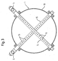
- FIG. 3 there are two in the tube arrangement 1 Dispensing lances 14, 15 are arranged, each of which has openings 16.
- the openings 16 are small in the area of the central axis of the tube arrangement 1 and are in the direction to the outer wall 10 always larger. This measure also achieves that in the outer area more of the second liquid in the Paper pulp suspension is mixed in as in the inner area because in the outer Area a larger volume flow of the second liquid flows.
- the metering lances 14, 15 are equipped with several rows of openings 16 can be, the rows not extending over the entire length of the metering lances 14, 15 must extend, but for example only in the wall 10 facing Area can be arranged to supply more of the second liquid there than in the middle of the pipe arrangement 1.
- the tube arrangement 1 (FIG. 4) has 10 flange covers on the outside of its wall 17, 18, 19, 20, by means of which the metering lances 2, 3 and 14, 15 crossed are held to each other. There can be any number of dosing lances in the Pipe arrangement 1 may be present, which is then preferably symmetrical about the Cross section are distributed.
- the tube arrangement 1 has a collar at each end 21, 22, via which it is connected to other elements of a pipeline.
- the Pipe arrangement 1 is slightly conical in the longitudinal direction.
- piping can be used according to the invention, for example, those with a rectangular or elliptical cross section.
- Sizes and distances of the openings as well as the number of rows of openings must be then according to the teaching of this invention to the selected cross section be adjusted.
- the metering lance 2 is shown in cross section, with lines 23 each Mark the centers of the openings 7.
- the openings 7, 16 are preferably as circular holes. But there can be any other forms of Openings are used.
Landscapes
- Chemical & Material Sciences (AREA)
- Chemical Kinetics & Catalysis (AREA)
- Paper (AREA)
- Accessories For Mixers (AREA)
- Diaphragms For Electromechanical Transducers (AREA)
Abstract
Description
- Fig. 1
- eine Schnittansicht einer Rohranordnung mit zwei jeweils in der Draufsicht dargestellten Dosierlanzen, wobei die Öffnungen in den Dosierlanzen in unterschiedlichen Abständen zueinander angeordnet sind;
- Fig. 2
- eine Draufsicht auf eine Dosierlanze gemäß Fig. 1 mit einem in Strömungsrichtung der zweiten Flüssigkeit vorgeordneten Mischer;
- Fig. 3
- eine Schnittansicht einer anderen Rohranordnung mit zwei jeweils in der Draufsicht dargestellten Dosierlanzen, wobei die Öffnungen in den Dosierlanzen verschiedene Größen haben;
- Fig. 4
- eine Seitenansicht des Abschnitts der Rohranordnung, in dem die Dosierlanzen angeordnet sind, und
- Fig. 5
- eine Schnittansicht einer Dosierlanze aus Fig. 4 gemäß einer Schnittlinie A-A.
Claims (13)
- Rohrförmige Anordnung (1) zum Durchleiten einer Papierfaserstoffsuspension, in die durch eine Einmischeinrichtung eine zweite Flüssigkeit zuführbar ist,
dadurch gekennzeichnet, dass die Einmischeinrichtung eine Mehrzahl von Öffnungen (7, 16) aufweist und dass die Öffnungen (7, 16) um so größer sind, je größer die die Öffnungen (7, 16) umströmenden Teilvolumenströme der Papierfaserstoffsuspension sind. - Rohrförmige Anordnung (1) zum Durchleiten einer Papierfaserstoffsuspension, in die durch eine Einmischeinrichtung eine zweite Flüssigkeit zuführbar ist, insbesondere nach Anspruch 1,
dadurch gekennzeichnet, dass die Einmischeinrichtung eine Mehrzahl von Öffnungen (7, 16) zum Einmischen der zweiten Flüssigkeit aufweist und dass die Abstände der Öffnungen (7, 16) um so kleiner sind, je größer die die Öffnungen (7, 16) umströmenden Teilvolumenströme der Papierfaserstoffsuspension sind. - Rohrförmige Anordnung (1) zum Durchleiten einer Papierfaserstoffsuspension, in die durch eine Einmischeinrichtung eine zweite Flüssigkeit zuführbar ist, insbesondere nach Anspruch 1 oder 2,
dadurch gekennzeichnet, dass die Einmischeinrichtung eine Mehrzahl von Öffnungen (7, 16) zum Einmischen der zweiten Flüssigkeit aufweist und dass die Einströmwinkel der aus den Öffnungen (7, 16) herausströmenden der zweiten Flüssigkeit entsprechend den sie umströmenden Teilvolumenströmen der Papierfaserstoffsuspension zueinander angeordnet sind. - Anordnung (1) nach einem der Ansprüche 1 bis 3,
dadurch gekennzeichnet, dass die Einmischeinrichtung als mindestens eine Dosierlanze (3, 4; 14, 15) mit mindestens einer Reihe von Bohrungen (7, 16) ausgebildet ist. - Anordnung (1) nach Anspruch 4,
dadurch gekennzeichnet, dass in dem rohrförmigen Körper zwei Dosierlanzen (3, 4; 14, 15) vorhanden sind, die unter spitzen oder einem stumpfen Winkel, insbesondere unter einem 90°-Winkel zueinander angeordnet sind. - Anordnung (1) nach Anspruch 4 oder 5,
dadurch gekennzeichnet, dass die mindestens eine Dosierlanze (3, 4; 14, 15) mit einem Anschluss (13) für die Zuführung von Verdünnungswasser ausgestattet ist. - Anordnung (1) nach Anspruch 6,
dadurch gekennzeichnet, dass der Anschluss (13) als Wasserstrahlpumpe oder nach Art einer Wasserstrahlpumpe ausgebildet ist. - Anordnung (1) nach einem der Ansprüche 4 bis 7,
dadurch gekennzeichnet, dass ein statischer Mischer unmittelbar vor mindestens einer der Dosierlanzen (3, 4; 14, 15) angebracht ist. - Anordnung (1) nach einem der Ansprüche 4 bis 8,
dadurch gekennzeichnet, dass die mindestens eine Dosierlanze (3, 4; 14, 15) drehbar in der Anordnung (1) gelagert ist. - Verfahren zum Durchleiten einer Papierfaserstoffsuspension durch eine rohrförmige Anordnung (1), wobei durch eine Einmischeinrichtung eine zweite Flüssigkeit zugeführt wird,
dadurch gekennzeichnet, dass die zweite Flüssigkeit durch an den jeweiligen Teilvolumenstrom der Papierfaserstoffsuspension angepasste Größen von Öffnungen (7, 16) in der Einmischeinrichtung in die rohrförmige Anordnung (1) eingebracht wird. - Verfahren zum Durchleiten einer Papierfaserstoffsuspension durch eine rohrförmige Anordnung (1), wobei durch eine Einmischeinrichtung die zweite Flüssigkeit zugeführt wird, insbesondere nach Anspruch 10,
dadurch gekennzeichnet, dass die zweite Flüssigkeit durch an den jeweiligen Teilvolumenstrom der Papierfaserstoffsuspension angepasste Abstände von Öffnungen (7, 16) in der Einmischeinrichtung in die rohrförmige Anordnung (1) eingebracht wird. - Verfahren nach Anspruch 10 oder 11,
dadurch gekennzeichnet, dass die zweite Flüssigkeit unmittelbar vor seiner Einbringung in eine Rohrleitung oder Dosierlanze (3, 4; 14, 15) , aus der es in die Papierfaserstoffsuspension eingemischt wird, über die Kinetik eines Additivs und eines Verdünnungsmittels, aus denen sich die zweite Flüssigkeit zusammensetzt, auf die für die Durchmischung zwischen der Papierfaserstoffsuspension und der zweiten Flüssigkeit erforderliche Mischenergie eingestellt wird. - Verfahren nach Anspruch 12,
dadurch gekennzeichnet, dass Verdünnungsmittel, insbesondere Wasser, mit einer Geschwindigkeit von 1 bis 4 m/s strömt, dass das Additiv mit einer Geschwindigkeit von 2 bis 10 m/s strömt und dass die daraus zusammengesetzte zweite Flüssigkeit mit einer Geschwindigkeit von 0,2 bis 5 m/s in die Papierfaserstoffsuspension einströmt.
Applications Claiming Priority (2)
| Application Number | Priority Date | Filing Date | Title |
|---|---|---|---|
| DE10317865A DE10317865A1 (de) | 2003-04-09 | 2003-04-09 | Anordnung und Verfahren zum Zuführen einer zweiten Flüssigkeit zu einer Papierfaserstoffsuspension |
| DE10317865 | 2003-04-09 |
Publications (2)
| Publication Number | Publication Date |
|---|---|
| EP1467018A1 true EP1467018A1 (de) | 2004-10-13 |
| EP1467018B1 EP1467018B1 (de) | 2009-04-29 |
Family
ID=32864489
Family Applications (1)
| Application Number | Title | Priority Date | Filing Date |
|---|---|---|---|
| EP04400015A Expired - Lifetime EP1467018B1 (de) | 2003-04-09 | 2004-03-16 | Anordnung und Verfahren zum Einmischen einer Flüssigkeit in eine Papierfaserstoffsuspension |
Country Status (3)
| Country | Link |
|---|---|
| EP (1) | EP1467018B1 (de) |
| AT (1) | ATE430215T1 (de) |
| DE (3) | DE20321803U1 (de) |
Cited By (3)
| Publication number | Priority date | Publication date | Assignee | Title |
|---|---|---|---|---|
| WO2012117003A1 (de) * | 2011-03-01 | 2012-09-07 | Basf Se | Verfahren und vorrichtung zur vermischung zweier fluidströme |
| US9364802B2 (en) | 2011-03-01 | 2016-06-14 | Basf Se | Method and apparatus for the intermixing of two fluid streams |
| EP3095528A3 (de) * | 2015-04-02 | 2017-02-22 | RUBLIC + CANZLER GmbH | Austragvorrichtung für pastöse massen |
Families Citing this family (6)
| Publication number | Priority date | Publication date | Assignee | Title |
|---|---|---|---|---|
| DE102008000258A1 (de) | 2008-02-08 | 2009-08-13 | Voith Patent Gmbh | Mischanordnung |
| DE102008000256A1 (de) | 2008-02-08 | 2009-08-13 | Voith Patent Gmbh | Misch- und Verdünnungsanordnung |
| DE102010007303A1 (de) * | 2010-02-08 | 2011-08-11 | Outotec Oyj | Verfahren und Vorrichtung zum Einstellen der Konzentration von Säuren oder Laugen |
| DE102011011214B4 (de) * | 2011-02-14 | 2015-08-13 | TEC artec GmbH | Vorrichtung zum Einbringen von Polymeren in einen Fluidstrom |
| US10066530B2 (en) * | 2015-11-17 | 2018-09-04 | Ford Global Technologies, Llc | Exhaust gas mixer |
| DE102019111122A1 (de) | 2019-04-30 | 2020-11-05 | Voith Patent Gmbh | Injektordüse |
Citations (5)
| Publication number | Priority date | Publication date | Assignee | Title |
|---|---|---|---|---|
| DE2844983A1 (de) * | 1977-10-18 | 1979-04-19 | Shell Int Research | Vorrichtung zum mischen von zwei fluiden und mit ihr ausgestatteter schieber |
| DE4416898A1 (de) * | 1994-05-13 | 1995-11-30 | Voith Sulzer Papiermasch Gmbh | Stoffauflauf für eine Papiermaschine mit lokaler Zumischung von Fluid |
| DE4421352A1 (de) * | 1994-06-17 | 1995-12-21 | Specker Helmut | Verfahren und Vorrichtung zum Verdünnen von Flüssigkonzentrat mit Wasser |
| EP1126077A2 (de) * | 2000-02-09 | 2001-08-22 | Voith Paper Patent GmbH | Verfahren und Vorrichtung zur Stoffaufbereitung |
| WO2002072250A1 (en) * | 2001-02-21 | 2002-09-19 | Metso Paper Inc | Arrangement for mixing flows in papermaking process |
Family Cites Families (3)
| Publication number | Priority date | Publication date | Assignee | Title |
|---|---|---|---|---|
| DD246220A3 (de) * | 1984-12-21 | 1987-06-03 | Petrolchemisches Kombinat | Verfahren und vorrichtung zur dispergierung und koaleszenz nicht miteinander mischbarer fluessigkeiten |
| SE455795B (sv) * | 1986-12-03 | 1988-08-08 | Mo Och Domsjoe Ab | Forfarande och anordning for framstellning av fyllmedelshaltigt papper |
| FI108802B (fi) * | 1998-02-26 | 2002-03-28 | Wetend Technologies Oy | Menetelmä ja laite kemikaalin syöttämiseksi nestevirtaan sekä paperikoneen syöttöjärjestelmä |
-
2003
- 2003-04-09 DE DE20321803U patent/DE20321803U1/de not_active Expired - Lifetime
- 2003-04-09 DE DE10317865A patent/DE10317865A1/de not_active Withdrawn
-
2004
- 2004-03-16 DE DE502004009406T patent/DE502004009406D1/de not_active Expired - Lifetime
- 2004-03-16 EP EP04400015A patent/EP1467018B1/de not_active Expired - Lifetime
- 2004-03-16 AT AT04400015T patent/ATE430215T1/de active
Patent Citations (5)
| Publication number | Priority date | Publication date | Assignee | Title |
|---|---|---|---|---|
| DE2844983A1 (de) * | 1977-10-18 | 1979-04-19 | Shell Int Research | Vorrichtung zum mischen von zwei fluiden und mit ihr ausgestatteter schieber |
| DE4416898A1 (de) * | 1994-05-13 | 1995-11-30 | Voith Sulzer Papiermasch Gmbh | Stoffauflauf für eine Papiermaschine mit lokaler Zumischung von Fluid |
| DE4421352A1 (de) * | 1994-06-17 | 1995-12-21 | Specker Helmut | Verfahren und Vorrichtung zum Verdünnen von Flüssigkonzentrat mit Wasser |
| EP1126077A2 (de) * | 2000-02-09 | 2001-08-22 | Voith Paper Patent GmbH | Verfahren und Vorrichtung zur Stoffaufbereitung |
| WO2002072250A1 (en) * | 2001-02-21 | 2002-09-19 | Metso Paper Inc | Arrangement for mixing flows in papermaking process |
Cited By (6)
| Publication number | Priority date | Publication date | Assignee | Title |
|---|---|---|---|---|
| WO2012117003A1 (de) * | 2011-03-01 | 2012-09-07 | Basf Se | Verfahren und vorrichtung zur vermischung zweier fluidströme |
| CN103402618A (zh) * | 2011-03-01 | 2013-11-20 | 巴斯夫欧洲公司 | 用于混合两种流体流动的方法和装置 |
| JP2014506832A (ja) * | 2011-03-01 | 2014-03-20 | ビーエーエスエフ ソシエタス・ヨーロピア | 2流体の流れの混合方法及びその装置 |
| CN103402618B (zh) * | 2011-03-01 | 2015-10-21 | 巴斯夫欧洲公司 | 用于混合两种流体流动的方法和装置 |
| US9364802B2 (en) | 2011-03-01 | 2016-06-14 | Basf Se | Method and apparatus for the intermixing of two fluid streams |
| EP3095528A3 (de) * | 2015-04-02 | 2017-02-22 | RUBLIC + CANZLER GmbH | Austragvorrichtung für pastöse massen |
Also Published As
| Publication number | Publication date |
|---|---|
| DE10317865A1 (de) | 2004-10-21 |
| DE502004009406D1 (de) | 2009-06-10 |
| DE20321803U1 (de) | 2010-04-08 |
| EP1467018B1 (de) | 2009-04-29 |
| ATE430215T1 (de) | 2009-05-15 |
Similar Documents
| Publication | Publication Date | Title |
|---|---|---|
| DE69934611T2 (de) | Verfahren und Vorrichtung zum Zuführen einer Chemikalie in eine Flüssigkeitsströmung | |
| DE4433744C2 (de) | Vorrichtung zum Vermischen von Medien zur Erzeugung flüssiger Systeme | |
| DE3045383C2 (de) | Vorrichtung zum Vermischen eines Konzentrats mit Wasser | |
| EP2379803B1 (de) | Stoffauflauf für eine maschine zur herstellung einer faserstoffbahn | |
| EP2566611B1 (de) | Mischverfahren und mischanordnung | |
| EP0629739A1 (de) | Stoffauflauf für eine Papiermaschine | |
| DE3046969A1 (de) | Vorrichtung zur behandlung von sich bewegenden suspensionen | |
| DE2632456C2 (de) | Injektionsvorrichtung für einen Doppelrohr-Bohrstrang | |
| DE2739626C2 (de) | ||
| EP1467018B1 (de) | Anordnung und Verfahren zum Einmischen einer Flüssigkeit in eine Papierfaserstoffsuspension | |
| EP2714229B1 (de) | Filtriervorrichtung für hochviskose fluide | |
| DE60032811T2 (de) | Verfahren und vorrichtung zur mischung von faserstoffkomponenten für die herstellung von papier | |
| EP0205654B2 (de) | Vorrichtung zum Aufbringen eines Flüssigkeitsfilmes grosser Breite auf eine Warenbahn | |
| DE2532528A1 (de) | Verfahren zur einstellung eines vorbestimmten verteilungsgesetzes des durchflusses in einem stroemenden mediumsstrom sowie vorrichtung zur durchfuehrung des verfahrens | |
| DE3029194C2 (de) | Verschneidevorrichtung für Wasserenthärtungsanlagen | |
| DE851301C (de) | Vorrichtung zum gleichmaessigen Verteilen des einer Papier- od. dgl. Entwaesserungsmaschine zugefuehrten Faserstoff-Wasser-Gemisches | |
| DE2232020B2 (de) | Flüssigkeitsverteilelement für Wasch- und Geschirrspülmaschinen | |
| DE102011075558A1 (de) | Mischdüse | |
| DE102008000256A1 (de) | Misch- und Verdünnungsanordnung | |
| WO2009097878A1 (de) | Mischanordnung und verfahren | |
| EP3962636B1 (de) | Injektordüse, mischanordnung und anwendung der injektordüse | |
| DE102010029388A1 (de) | Chemikalieneinmischung | |
| DE1782047C (de) | Vorrichtung zum kontinuierlichen Homogenisieren eines Gemisches von Flüssigkeiten | |
| DE2045920A1 (de) | Vorrichtung zur Bildung einer Fasersuspension und Zuführung derselben zum Sieb einer Faservliesbildungseinrichtung | |
| DE29505082U1 (de) | Gerät zum Herstellen eines flüssigen Gemisches aus hygroskopischem Pulvermterial und Wasser |
Legal Events
| Date | Code | Title | Description |
|---|---|---|---|
| PUAI | Public reference made under article 153(3) epc to a published international application that has entered the european phase |
Free format text: ORIGINAL CODE: 0009012 |
|
| AK | Designated contracting states |
Kind code of ref document: A1 Designated state(s): AT BE BG CH CY CZ DE DK EE ES FI FR GB GR HU IE IT LI LU MC NL PL PT RO SE SI SK TR |
|
| AX | Request for extension of the european patent |
Extension state: AL HR LT LV MK |
|
| 17P | Request for examination filed |
Effective date: 20050413 |
|
| AKX | Designation fees paid |
Designated state(s): AT CH DE FI LI SE |
|
| RAP1 | Party data changed (applicant data changed or rights of an application transferred) |
Owner name: VOITH PATENT GMBH |
|
| 17Q | First examination report despatched |
Effective date: 20070612 |
|
| GRAP | Despatch of communication of intention to grant a patent |
Free format text: ORIGINAL CODE: EPIDOSNIGR1 |
|
| GRAS | Grant fee paid |
Free format text: ORIGINAL CODE: EPIDOSNIGR3 |
|
| GRAA | (expected) grant |
Free format text: ORIGINAL CODE: 0009210 |
|
| AK | Designated contracting states |
Kind code of ref document: B1 Designated state(s): AT CH DE FI LI SE |
|
| REG | Reference to a national code |
Ref country code: CH Ref legal event code: EP |
|
| REF | Corresponds to: |
Ref document number: 502004009406 Country of ref document: DE Date of ref document: 20090610 Kind code of ref document: P |
|
| REG | Reference to a national code |
Ref country code: SE Ref legal event code: TRGR |
|
| PLBE | No opposition filed within time limit |
Free format text: ORIGINAL CODE: 0009261 |
|
| STAA | Information on the status of an ep patent application or granted ep patent |
Free format text: STATUS: NO OPPOSITION FILED WITHIN TIME LIMIT |
|
| 26N | No opposition filed |
Effective date: 20100201 |
|
| PGFP | Annual fee paid to national office [announced via postgrant information from national office to epo] |
Ref country code: CH Payment date: 20110324 Year of fee payment: 8 |
|
| REG | Reference to a national code |
Ref country code: CH Ref legal event code: PL |
|
| PG25 | Lapsed in a contracting state [announced via postgrant information from national office to epo] |
Ref country code: LI Free format text: LAPSE BECAUSE OF NON-PAYMENT OF DUE FEES Effective date: 20120331 Ref country code: CH Free format text: LAPSE BECAUSE OF NON-PAYMENT OF DUE FEES Effective date: 20120331 |
|
| PGFP | Annual fee paid to national office [announced via postgrant information from national office to epo] |
Ref country code: FI Payment date: 20150311 Year of fee payment: 12 Ref country code: DE Payment date: 20150320 Year of fee payment: 12 |
|
| PGFP | Annual fee paid to national office [announced via postgrant information from national office to epo] |
Ref country code: AT Payment date: 20150320 Year of fee payment: 12 Ref country code: SE Payment date: 20150319 Year of fee payment: 12 |
|
| REG | Reference to a national code |
Ref country code: DE Ref legal event code: R119 Ref document number: 502004009406 Country of ref document: DE |
|
| PG25 | Lapsed in a contracting state [announced via postgrant information from national office to epo] |
Ref country code: FI Free format text: LAPSE BECAUSE OF NON-PAYMENT OF DUE FEES Effective date: 20160316 |
|
| REG | Reference to a national code |
Ref country code: SE Ref legal event code: EUG |
|
| REG | Reference to a national code |
Ref country code: AT Ref legal event code: MM01 Ref document number: 430215 Country of ref document: AT Kind code of ref document: T Effective date: 20160316 |
|
| PG25 | Lapsed in a contracting state [announced via postgrant information from national office to epo] |
Ref country code: SE Free format text: LAPSE BECAUSE OF NON-PAYMENT OF DUE FEES Effective date: 20160317 |
|
| PG25 | Lapsed in a contracting state [announced via postgrant information from national office to epo] |
Ref country code: DE Free format text: LAPSE BECAUSE OF NON-PAYMENT OF DUE FEES Effective date: 20161001 |
|
| PG25 | Lapsed in a contracting state [announced via postgrant information from national office to epo] |
Ref country code: AT Free format text: LAPSE BECAUSE OF NON-PAYMENT OF DUE FEES Effective date: 20160316 |