EP1466773A2 - Antriebsvorrichtung zum Antreiben von Zusatzgeräten für ein Fahrzeug - Google Patents
Antriebsvorrichtung zum Antreiben von Zusatzgeräten für ein Fahrzeug Download PDFInfo
- Publication number
- EP1466773A2 EP1466773A2 EP04101458A EP04101458A EP1466773A2 EP 1466773 A2 EP1466773 A2 EP 1466773A2 EP 04101458 A EP04101458 A EP 04101458A EP 04101458 A EP04101458 A EP 04101458A EP 1466773 A2 EP1466773 A2 EP 1466773A2
- Authority
- EP
- European Patent Office
- Prior art keywords
- electric machine
- drive device
- pto
- gear
- vehicle
- Prior art date
- Legal status (The legal status is an assumption and is not a legal conclusion. Google has not performed a legal analysis and makes no representation as to the accuracy of the status listed.)
- Granted
Links
- 238000002485 combustion reaction Methods 0.000 claims abstract description 59
- 230000005540 biological transmission Effects 0.000 claims description 38
- 239000002826 coolant Substances 0.000 claims description 12
- 238000001816 cooling Methods 0.000 claims description 10
- 238000005461 lubrication Methods 0.000 claims description 4
- 230000001419 dependent effect Effects 0.000 claims description 3
- 238000010438 heat treatment Methods 0.000 claims description 3
- 238000005457 optimization Methods 0.000 claims description 3
- 239000000446 fuel Substances 0.000 claims description 2
- 238000004804 winding Methods 0.000 claims description 2
- 230000000979 retarding effect Effects 0.000 claims 1
- 238000011161 development Methods 0.000 description 6
- 230000018109 developmental process Effects 0.000 description 6
- 238000013461 design Methods 0.000 description 4
- 238000013519 translation Methods 0.000 description 4
- 239000003921 oil Substances 0.000 description 3
- 238000010276 construction Methods 0.000 description 2
- 238000005259 measurement Methods 0.000 description 2
- 238000012546 transfer Methods 0.000 description 2
- 230000006978 adaptation Effects 0.000 description 1
- 230000008878 coupling Effects 0.000 description 1
- 238000010168 coupling process Methods 0.000 description 1
- 238000005859 coupling reaction Methods 0.000 description 1
- 238000009429 electrical wiring Methods 0.000 description 1
- 230000005611 electricity Effects 0.000 description 1
- 230000002349 favourable effect Effects 0.000 description 1
- 239000012208 gear oil Substances 0.000 description 1
- 230000009347 mechanical transmission Effects 0.000 description 1
- 238000012986 modification Methods 0.000 description 1
- 230000004048 modification Effects 0.000 description 1
- 230000000737 periodic effect Effects 0.000 description 1
- 238000009987 spinning Methods 0.000 description 1
Images


Classifications
-
- B—PERFORMING OPERATIONS; TRANSPORTING
- B60—VEHICLES IN GENERAL
- B60K—ARRANGEMENT OR MOUNTING OF PROPULSION UNITS OR OF TRANSMISSIONS IN VEHICLES; ARRANGEMENT OR MOUNTING OF PLURAL DIVERSE PRIME-MOVERS IN VEHICLES; AUXILIARY DRIVES FOR VEHICLES; INSTRUMENTATION OR DASHBOARDS FOR VEHICLES; ARRANGEMENTS IN CONNECTION WITH COOLING, AIR INTAKE, GAS EXHAUST OR FUEL SUPPLY OF PROPULSION UNITS IN VEHICLES
- B60K6/00—Arrangement or mounting of plural diverse prime-movers for mutual or common propulsion, e.g. hybrid propulsion systems comprising electric motors and internal combustion engines ; Control systems therefor, i.e. systems controlling two or more prime movers, or controlling one of these prime movers and any of the transmission, drive or drive units Informative references: mechanical gearings with secondary electric drive F16H3/72; arrangements for handling mechanical energy structurally associated with the dynamo-electric machine H02K7/00; machines comprising structurally interrelated motor and generator parts H02K51/00; dynamo-electric machines not otherwise provided for in H02K see H02K99/00
- B60K6/20—Arrangement or mounting of plural diverse prime-movers for mutual or common propulsion, e.g. hybrid propulsion systems comprising electric motors and internal combustion engines ; Control systems therefor, i.e. systems controlling two or more prime movers, or controlling one of these prime movers and any of the transmission, drive or drive units Informative references: mechanical gearings with secondary electric drive F16H3/72; arrangements for handling mechanical energy structurally associated with the dynamo-electric machine H02K7/00; machines comprising structurally interrelated motor and generator parts H02K51/00; dynamo-electric machines not otherwise provided for in H02K see H02K99/00 the prime-movers consisting of electric motors and internal combustion engines, e.g. HEVs
- B60K6/22—Arrangement or mounting of plural diverse prime-movers for mutual or common propulsion, e.g. hybrid propulsion systems comprising electric motors and internal combustion engines ; Control systems therefor, i.e. systems controlling two or more prime movers, or controlling one of these prime movers and any of the transmission, drive or drive units Informative references: mechanical gearings with secondary electric drive F16H3/72; arrangements for handling mechanical energy structurally associated with the dynamo-electric machine H02K7/00; machines comprising structurally interrelated motor and generator parts H02K51/00; dynamo-electric machines not otherwise provided for in H02K see H02K99/00 the prime-movers consisting of electric motors and internal combustion engines, e.g. HEVs characterised by apparatus, components or means specially adapted for HEVs
- B60K6/36—Arrangement or mounting of plural diverse prime-movers for mutual or common propulsion, e.g. hybrid propulsion systems comprising electric motors and internal combustion engines ; Control systems therefor, i.e. systems controlling two or more prime movers, or controlling one of these prime movers and any of the transmission, drive or drive units Informative references: mechanical gearings with secondary electric drive F16H3/72; arrangements for handling mechanical energy structurally associated with the dynamo-electric machine H02K7/00; machines comprising structurally interrelated motor and generator parts H02K51/00; dynamo-electric machines not otherwise provided for in H02K see H02K99/00 the prime-movers consisting of electric motors and internal combustion engines, e.g. HEVs characterised by apparatus, components or means specially adapted for HEVs characterised by the transmission gearings
- B60K6/365—Arrangement or mounting of plural diverse prime-movers for mutual or common propulsion, e.g. hybrid propulsion systems comprising electric motors and internal combustion engines ; Control systems therefor, i.e. systems controlling two or more prime movers, or controlling one of these prime movers and any of the transmission, drive or drive units Informative references: mechanical gearings with secondary electric drive F16H3/72; arrangements for handling mechanical energy structurally associated with the dynamo-electric machine H02K7/00; machines comprising structurally interrelated motor and generator parts H02K51/00; dynamo-electric machines not otherwise provided for in H02K see H02K99/00 the prime-movers consisting of electric motors and internal combustion engines, e.g. HEVs characterised by apparatus, components or means specially adapted for HEVs characterised by the transmission gearings with the gears having orbital motion
-
- A—HUMAN NECESSITIES
- A01—AGRICULTURE; FORESTRY; ANIMAL HUSBANDRY; HUNTING; TRAPPING; FISHING
- A01B—SOIL WORKING IN AGRICULTURE OR FORESTRY; PARTS, DETAILS, OR ACCESSORIES OF AGRICULTURAL MACHINES OR IMPLEMENTS, IN GENERAL
- A01B71/00—Construction or arrangement of setting or adjusting mechanisms, of implement or tool drive or of power take-off; Means for protecting parts against dust, or the like; Adapting machine elements to or for agricultural purposes
- A01B71/06—Special adaptations of coupling means between power take-off and transmission shaft to the implement or machine
-
- B—PERFORMING OPERATIONS; TRANSPORTING
- B60—VEHICLES IN GENERAL
- B60K—ARRANGEMENT OR MOUNTING OF PROPULSION UNITS OR OF TRANSMISSIONS IN VEHICLES; ARRANGEMENT OR MOUNTING OF PLURAL DIVERSE PRIME-MOVERS IN VEHICLES; AUXILIARY DRIVES FOR VEHICLES; INSTRUMENTATION OR DASHBOARDS FOR VEHICLES; ARRANGEMENTS IN CONNECTION WITH COOLING, AIR INTAKE, GAS EXHAUST OR FUEL SUPPLY OF PROPULSION UNITS IN VEHICLES
- B60K17/00—Arrangement or mounting of transmissions in vehicles
- B60K17/28—Arrangement or mounting of transmissions in vehicles characterised by arrangement, location, or type of power take-off
-
- B—PERFORMING OPERATIONS; TRANSPORTING
- B60—VEHICLES IN GENERAL
- B60K—ARRANGEMENT OR MOUNTING OF PROPULSION UNITS OR OF TRANSMISSIONS IN VEHICLES; ARRANGEMENT OR MOUNTING OF PLURAL DIVERSE PRIME-MOVERS IN VEHICLES; AUXILIARY DRIVES FOR VEHICLES; INSTRUMENTATION OR DASHBOARDS FOR VEHICLES; ARRANGEMENTS IN CONNECTION WITH COOLING, AIR INTAKE, GAS EXHAUST OR FUEL SUPPLY OF PROPULSION UNITS IN VEHICLES
- B60K6/00—Arrangement or mounting of plural diverse prime-movers for mutual or common propulsion, e.g. hybrid propulsion systems comprising electric motors and internal combustion engines ; Control systems therefor, i.e. systems controlling two or more prime movers, or controlling one of these prime movers and any of the transmission, drive or drive units Informative references: mechanical gearings with secondary electric drive F16H3/72; arrangements for handling mechanical energy structurally associated with the dynamo-electric machine H02K7/00; machines comprising structurally interrelated motor and generator parts H02K51/00; dynamo-electric machines not otherwise provided for in H02K see H02K99/00
- B60K6/20—Arrangement or mounting of plural diverse prime-movers for mutual or common propulsion, e.g. hybrid propulsion systems comprising electric motors and internal combustion engines ; Control systems therefor, i.e. systems controlling two or more prime movers, or controlling one of these prime movers and any of the transmission, drive or drive units Informative references: mechanical gearings with secondary electric drive F16H3/72; arrangements for handling mechanical energy structurally associated with the dynamo-electric machine H02K7/00; machines comprising structurally interrelated motor and generator parts H02K51/00; dynamo-electric machines not otherwise provided for in H02K see H02K99/00 the prime-movers consisting of electric motors and internal combustion engines, e.g. HEVs
- B60K6/22—Arrangement or mounting of plural diverse prime-movers for mutual or common propulsion, e.g. hybrid propulsion systems comprising electric motors and internal combustion engines ; Control systems therefor, i.e. systems controlling two or more prime movers, or controlling one of these prime movers and any of the transmission, drive or drive units Informative references: mechanical gearings with secondary electric drive F16H3/72; arrangements for handling mechanical energy structurally associated with the dynamo-electric machine H02K7/00; machines comprising structurally interrelated motor and generator parts H02K51/00; dynamo-electric machines not otherwise provided for in H02K see H02K99/00 the prime-movers consisting of electric motors and internal combustion engines, e.g. HEVs characterised by apparatus, components or means specially adapted for HEVs
- B60K6/40—Arrangement or mounting of plural diverse prime-movers for mutual or common propulsion, e.g. hybrid propulsion systems comprising electric motors and internal combustion engines ; Control systems therefor, i.e. systems controlling two or more prime movers, or controlling one of these prime movers and any of the transmission, drive or drive units Informative references: mechanical gearings with secondary electric drive F16H3/72; arrangements for handling mechanical energy structurally associated with the dynamo-electric machine H02K7/00; machines comprising structurally interrelated motor and generator parts H02K51/00; dynamo-electric machines not otherwise provided for in H02K see H02K99/00 the prime-movers consisting of electric motors and internal combustion engines, e.g. HEVs characterised by apparatus, components or means specially adapted for HEVs characterised by the assembly or relative disposition of components
-
- B—PERFORMING OPERATIONS; TRANSPORTING
- B60—VEHICLES IN GENERAL
- B60K—ARRANGEMENT OR MOUNTING OF PROPULSION UNITS OR OF TRANSMISSIONS IN VEHICLES; ARRANGEMENT OR MOUNTING OF PLURAL DIVERSE PRIME-MOVERS IN VEHICLES; AUXILIARY DRIVES FOR VEHICLES; INSTRUMENTATION OR DASHBOARDS FOR VEHICLES; ARRANGEMENTS IN CONNECTION WITH COOLING, AIR INTAKE, GAS EXHAUST OR FUEL SUPPLY OF PROPULSION UNITS IN VEHICLES
- B60K6/00—Arrangement or mounting of plural diverse prime-movers for mutual or common propulsion, e.g. hybrid propulsion systems comprising electric motors and internal combustion engines ; Control systems therefor, i.e. systems controlling two or more prime movers, or controlling one of these prime movers and any of the transmission, drive or drive units Informative references: mechanical gearings with secondary electric drive F16H3/72; arrangements for handling mechanical energy structurally associated with the dynamo-electric machine H02K7/00; machines comprising structurally interrelated motor and generator parts H02K51/00; dynamo-electric machines not otherwise provided for in H02K see H02K99/00
- B60K6/20—Arrangement or mounting of plural diverse prime-movers for mutual or common propulsion, e.g. hybrid propulsion systems comprising electric motors and internal combustion engines ; Control systems therefor, i.e. systems controlling two or more prime movers, or controlling one of these prime movers and any of the transmission, drive or drive units Informative references: mechanical gearings with secondary electric drive F16H3/72; arrangements for handling mechanical energy structurally associated with the dynamo-electric machine H02K7/00; machines comprising structurally interrelated motor and generator parts H02K51/00; dynamo-electric machines not otherwise provided for in H02K see H02K99/00 the prime-movers consisting of electric motors and internal combustion engines, e.g. HEVs
- B60K6/42—Arrangement or mounting of plural diverse prime-movers for mutual or common propulsion, e.g. hybrid propulsion systems comprising electric motors and internal combustion engines ; Control systems therefor, i.e. systems controlling two or more prime movers, or controlling one of these prime movers and any of the transmission, drive or drive units Informative references: mechanical gearings with secondary electric drive F16H3/72; arrangements for handling mechanical energy structurally associated with the dynamo-electric machine H02K7/00; machines comprising structurally interrelated motor and generator parts H02K51/00; dynamo-electric machines not otherwise provided for in H02K see H02K99/00 the prime-movers consisting of electric motors and internal combustion engines, e.g. HEVs characterised by the architecture of the hybrid electric vehicle
- B60K6/44—Series-parallel type
- B60K6/445—Differential gearing distribution type
-
- B—PERFORMING OPERATIONS; TRANSPORTING
- B60—VEHICLES IN GENERAL
- B60K—ARRANGEMENT OR MOUNTING OF PROPULSION UNITS OR OF TRANSMISSIONS IN VEHICLES; ARRANGEMENT OR MOUNTING OF PLURAL DIVERSE PRIME-MOVERS IN VEHICLES; AUXILIARY DRIVES FOR VEHICLES; INSTRUMENTATION OR DASHBOARDS FOR VEHICLES; ARRANGEMENTS IN CONNECTION WITH COOLING, AIR INTAKE, GAS EXHAUST OR FUEL SUPPLY OF PROPULSION UNITS IN VEHICLES
- B60K6/00—Arrangement or mounting of plural diverse prime-movers for mutual or common propulsion, e.g. hybrid propulsion systems comprising electric motors and internal combustion engines ; Control systems therefor, i.e. systems controlling two or more prime movers, or controlling one of these prime movers and any of the transmission, drive or drive units Informative references: mechanical gearings with secondary electric drive F16H3/72; arrangements for handling mechanical energy structurally associated with the dynamo-electric machine H02K7/00; machines comprising structurally interrelated motor and generator parts H02K51/00; dynamo-electric machines not otherwise provided for in H02K see H02K99/00
- B60K6/20—Arrangement or mounting of plural diverse prime-movers for mutual or common propulsion, e.g. hybrid propulsion systems comprising electric motors and internal combustion engines ; Control systems therefor, i.e. systems controlling two or more prime movers, or controlling one of these prime movers and any of the transmission, drive or drive units Informative references: mechanical gearings with secondary electric drive F16H3/72; arrangements for handling mechanical energy structurally associated with the dynamo-electric machine H02K7/00; machines comprising structurally interrelated motor and generator parts H02K51/00; dynamo-electric machines not otherwise provided for in H02K see H02K99/00 the prime-movers consisting of electric motors and internal combustion engines, e.g. HEVs
- B60K6/50—Architecture of the driveline characterised by arrangement or kind of transmission units
- B60K6/52—Driving a plurality of drive axles, e.g. four-wheel drive
-
- B—PERFORMING OPERATIONS; TRANSPORTING
- B60—VEHICLES IN GENERAL
- B60L—PROPULSION OF ELECTRICALLY-PROPELLED VEHICLES; SUPPLYING ELECTRIC POWER FOR AUXILIARY EQUIPMENT OF ELECTRICALLY-PROPELLED VEHICLES; ELECTRODYNAMIC BRAKE SYSTEMS FOR VEHICLES IN GENERAL; MAGNETIC SUSPENSION OR LEVITATION FOR VEHICLES; MONITORING OPERATING VARIABLES OF ELECTRICALLY-PROPELLED VEHICLES; ELECTRIC SAFETY DEVICES FOR ELECTRICALLY-PROPELLED VEHICLES
- B60L15/00—Methods, circuits, or devices for controlling the traction-motor speed of electrically-propelled vehicles
- B60L15/20—Methods, circuits, or devices for controlling the traction-motor speed of electrically-propelled vehicles for control of the vehicle or its driving motor to achieve a desired performance, e.g. speed, torque, programmed variation of speed
- B60L15/2054—Methods, circuits, or devices for controlling the traction-motor speed of electrically-propelled vehicles for control of the vehicle or its driving motor to achieve a desired performance, e.g. speed, torque, programmed variation of speed by controlling transmissions or clutches
-
- B—PERFORMING OPERATIONS; TRANSPORTING
- B60—VEHICLES IN GENERAL
- B60L—PROPULSION OF ELECTRICALLY-PROPELLED VEHICLES; SUPPLYING ELECTRIC POWER FOR AUXILIARY EQUIPMENT OF ELECTRICALLY-PROPELLED VEHICLES; ELECTRODYNAMIC BRAKE SYSTEMS FOR VEHICLES IN GENERAL; MAGNETIC SUSPENSION OR LEVITATION FOR VEHICLES; MONITORING OPERATING VARIABLES OF ELECTRICALLY-PROPELLED VEHICLES; ELECTRIC SAFETY DEVICES FOR ELECTRICALLY-PROPELLED VEHICLES
- B60L50/00—Electric propulsion with power supplied within the vehicle
- B60L50/10—Electric propulsion with power supplied within the vehicle using propulsion power supplied by engine-driven generators, e.g. generators driven by combustion engines
- B60L50/15—Electric propulsion with power supplied within the vehicle using propulsion power supplied by engine-driven generators, e.g. generators driven by combustion engines with additional electric power supply
-
- B—PERFORMING OPERATIONS; TRANSPORTING
- B60—VEHICLES IN GENERAL
- B60L—PROPULSION OF ELECTRICALLY-PROPELLED VEHICLES; SUPPLYING ELECTRIC POWER FOR AUXILIARY EQUIPMENT OF ELECTRICALLY-PROPELLED VEHICLES; ELECTRODYNAMIC BRAKE SYSTEMS FOR VEHICLES IN GENERAL; MAGNETIC SUSPENSION OR LEVITATION FOR VEHICLES; MONITORING OPERATING VARIABLES OF ELECTRICALLY-PROPELLED VEHICLES; ELECTRIC SAFETY DEVICES FOR ELECTRICALLY-PROPELLED VEHICLES
- B60L7/00—Electrodynamic brake systems for vehicles in general
-
- B—PERFORMING OPERATIONS; TRANSPORTING
- B60—VEHICLES IN GENERAL
- B60K—ARRANGEMENT OR MOUNTING OF PROPULSION UNITS OR OF TRANSMISSIONS IN VEHICLES; ARRANGEMENT OR MOUNTING OF PLURAL DIVERSE PRIME-MOVERS IN VEHICLES; AUXILIARY DRIVES FOR VEHICLES; INSTRUMENTATION OR DASHBOARDS FOR VEHICLES; ARRANGEMENTS IN CONNECTION WITH COOLING, AIR INTAKE, GAS EXHAUST OR FUEL SUPPLY OF PROPULSION UNITS IN VEHICLES
- B60K1/00—Arrangement or mounting of electrical propulsion units
- B60K1/02—Arrangement or mounting of electrical propulsion units comprising more than one electric motor
-
- B—PERFORMING OPERATIONS; TRANSPORTING
- B60—VEHICLES IN GENERAL
- B60K—ARRANGEMENT OR MOUNTING OF PROPULSION UNITS OR OF TRANSMISSIONS IN VEHICLES; ARRANGEMENT OR MOUNTING OF PLURAL DIVERSE PRIME-MOVERS IN VEHICLES; AUXILIARY DRIVES FOR VEHICLES; INSTRUMENTATION OR DASHBOARDS FOR VEHICLES; ARRANGEMENTS IN CONNECTION WITH COOLING, AIR INTAKE, GAS EXHAUST OR FUEL SUPPLY OF PROPULSION UNITS IN VEHICLES
- B60K1/00—Arrangement or mounting of electrical propulsion units
- B60K2001/003—Arrangement or mounting of electrical propulsion units with means for cooling the electrical propulsion units
-
- B—PERFORMING OPERATIONS; TRANSPORTING
- B60—VEHICLES IN GENERAL
- B60L—PROPULSION OF ELECTRICALLY-PROPELLED VEHICLES; SUPPLYING ELECTRIC POWER FOR AUXILIARY EQUIPMENT OF ELECTRICALLY-PROPELLED VEHICLES; ELECTRODYNAMIC BRAKE SYSTEMS FOR VEHICLES IN GENERAL; MAGNETIC SUSPENSION OR LEVITATION FOR VEHICLES; MONITORING OPERATING VARIABLES OF ELECTRICALLY-PROPELLED VEHICLES; ELECTRIC SAFETY DEVICES FOR ELECTRICALLY-PROPELLED VEHICLES
- B60L2200/00—Type of vehicles
- B60L2200/40—Working vehicles
-
- B—PERFORMING OPERATIONS; TRANSPORTING
- B60—VEHICLES IN GENERAL
- B60L—PROPULSION OF ELECTRICALLY-PROPELLED VEHICLES; SUPPLYING ELECTRIC POWER FOR AUXILIARY EQUIPMENT OF ELECTRICALLY-PROPELLED VEHICLES; ELECTRODYNAMIC BRAKE SYSTEMS FOR VEHICLES IN GENERAL; MAGNETIC SUSPENSION OR LEVITATION FOR VEHICLES; MONITORING OPERATING VARIABLES OF ELECTRICALLY-PROPELLED VEHICLES; ELECTRIC SAFETY DEVICES FOR ELECTRICALLY-PROPELLED VEHICLES
- B60L2240/00—Control parameters of input or output; Target parameters
- B60L2240/40—Drive Train control parameters
- B60L2240/42—Drive Train control parameters related to electric machines
- B60L2240/425—Temperature
-
- B—PERFORMING OPERATIONS; TRANSPORTING
- B60—VEHICLES IN GENERAL
- B60Y—INDEXING SCHEME RELATING TO ASPECTS CROSS-CUTTING VEHICLE TECHNOLOGY
- B60Y2200/00—Type of vehicle
- B60Y2200/20—Off-Road Vehicles
- B60Y2200/22—Agricultural vehicles
-
- Y—GENERAL TAGGING OF NEW TECHNOLOGICAL DEVELOPMENTS; GENERAL TAGGING OF CROSS-SECTIONAL TECHNOLOGIES SPANNING OVER SEVERAL SECTIONS OF THE IPC; TECHNICAL SUBJECTS COVERED BY FORMER USPC CROSS-REFERENCE ART COLLECTIONS [XRACs] AND DIGESTS
- Y02—TECHNOLOGIES OR APPLICATIONS FOR MITIGATION OR ADAPTATION AGAINST CLIMATE CHANGE
- Y02P—CLIMATE CHANGE MITIGATION TECHNOLOGIES IN THE PRODUCTION OR PROCESSING OF GOODS
- Y02P90/00—Enabling technologies with a potential contribution to greenhouse gas [GHG] emissions mitigation
- Y02P90/60—Electric or hybrid propulsion means for production processes
-
- Y—GENERAL TAGGING OF NEW TECHNOLOGICAL DEVELOPMENTS; GENERAL TAGGING OF CROSS-SECTIONAL TECHNOLOGIES SPANNING OVER SEVERAL SECTIONS OF THE IPC; TECHNICAL SUBJECTS COVERED BY FORMER USPC CROSS-REFERENCE ART COLLECTIONS [XRACs] AND DIGESTS
- Y02—TECHNOLOGIES OR APPLICATIONS FOR MITIGATION OR ADAPTATION AGAINST CLIMATE CHANGE
- Y02T—CLIMATE CHANGE MITIGATION TECHNOLOGIES RELATED TO TRANSPORTATION
- Y02T10/00—Road transport of goods or passengers
- Y02T10/60—Other road transportation technologies with climate change mitigation effect
- Y02T10/62—Hybrid vehicles
-
- Y—GENERAL TAGGING OF NEW TECHNOLOGICAL DEVELOPMENTS; GENERAL TAGGING OF CROSS-SECTIONAL TECHNOLOGIES SPANNING OVER SEVERAL SECTIONS OF THE IPC; TECHNICAL SUBJECTS COVERED BY FORMER USPC CROSS-REFERENCE ART COLLECTIONS [XRACs] AND DIGESTS
- Y02—TECHNOLOGIES OR APPLICATIONS FOR MITIGATION OR ADAPTATION AGAINST CLIMATE CHANGE
- Y02T—CLIMATE CHANGE MITIGATION TECHNOLOGIES RELATED TO TRANSPORTATION
- Y02T10/00—Road transport of goods or passengers
- Y02T10/60—Other road transportation technologies with climate change mitigation effect
- Y02T10/64—Electric machine technologies in electromobility
-
- Y—GENERAL TAGGING OF NEW TECHNOLOGICAL DEVELOPMENTS; GENERAL TAGGING OF CROSS-SECTIONAL TECHNOLOGIES SPANNING OVER SEVERAL SECTIONS OF THE IPC; TECHNICAL SUBJECTS COVERED BY FORMER USPC CROSS-REFERENCE ART COLLECTIONS [XRACs] AND DIGESTS
- Y02—TECHNOLOGIES OR APPLICATIONS FOR MITIGATION OR ADAPTATION AGAINST CLIMATE CHANGE
- Y02T—CLIMATE CHANGE MITIGATION TECHNOLOGIES RELATED TO TRANSPORTATION
- Y02T10/00—Road transport of goods or passengers
- Y02T10/60—Other road transportation technologies with climate change mitigation effect
- Y02T10/7072—Electromobility specific charging systems or methods for batteries, ultracapacitors, supercapacitors or double-layer capacitors
-
- Y—GENERAL TAGGING OF NEW TECHNOLOGICAL DEVELOPMENTS; GENERAL TAGGING OF CROSS-SECTIONAL TECHNOLOGIES SPANNING OVER SEVERAL SECTIONS OF THE IPC; TECHNICAL SUBJECTS COVERED BY FORMER USPC CROSS-REFERENCE ART COLLECTIONS [XRACs] AND DIGESTS
- Y02—TECHNOLOGIES OR APPLICATIONS FOR MITIGATION OR ADAPTATION AGAINST CLIMATE CHANGE
- Y02T—CLIMATE CHANGE MITIGATION TECHNOLOGIES RELATED TO TRANSPORTATION
- Y02T10/00—Road transport of goods or passengers
- Y02T10/60—Other road transportation technologies with climate change mitigation effect
- Y02T10/72—Electric energy management in electromobility
-
- Y—GENERAL TAGGING OF NEW TECHNOLOGICAL DEVELOPMENTS; GENERAL TAGGING OF CROSS-SECTIONAL TECHNOLOGIES SPANNING OVER SEVERAL SECTIONS OF THE IPC; TECHNICAL SUBJECTS COVERED BY FORMER USPC CROSS-REFERENCE ART COLLECTIONS [XRACs] AND DIGESTS
- Y10—TECHNICAL SUBJECTS COVERED BY FORMER USPC
- Y10S—TECHNICAL SUBJECTS COVERED BY FORMER USPC CROSS-REFERENCE ART COLLECTIONS [XRACs] AND DIGESTS
- Y10S903/00—Hybrid electric vehicles, HEVS
- Y10S903/902—Prime movers comprising electrical and internal combustion motors
- Y10S903/903—Prime movers comprising electrical and internal combustion motors having energy storing means, e.g. battery, capacitor
- Y10S903/904—Component specially adapted for hev
- Y10S903/915—Specific drive or transmission adapted for hev
- Y10S903/916—Specific drive or transmission adapted for hev with plurality of drive axles
Definitions
- the invention relates to a drive device for driving of additional equipment for a vehicle, in particular a agricultural or industrial utility vehicle, with one Mixing gear, an electric machine and a PTO, wherein a transmission interface of the mixing gear of a Internal combustion engine is drivable and wherein the electric Machine with a second transmission interface of the Mixed gear communicates.
- the present invention relates to a vehicle with such a drive device.
- work tools can be adapted, which have one PTO of the commercial vehicle are mechanically driven.
- One such work equipment is for example not one self-propelled round baler.
- the present invention is a drive interface for an accessory driven by the vehicle Understand that a mechanical torque is available provides.
- the object underlying the invention is seen therein a drive device for driving accessories for to specify a vehicle of the type mentioned by which overcome the aforementioned problems.
- a varying speed of Internal combustion engine is a substantially constant PTO shaft speed are provided.
- a variable PTO speed can be generated.
- a drive device of the beginning mentioned type characterized in that the PTO with a third transmission interface of the mixing gear in Connection stands.
- This can be a constant Input device requiring input by a Variation of the speed of the internal combustion engine with an im Essentially constant PTO speed can be operated.
- the PTO speed is thereby kept constant, that operated or driven the electric machine is that they have a speed variation of the internal combustion engine balances over the mixing gear.
- the electric machine could, for example, a battery or a Alternator be fed.
- Way the vehicle speed or the Engine speed even without stepless Powershift transmission in the vehicle driveline are varied, wherein the PTO speed with the help of electric Machine can be kept constant.
- a speed proportional to the speed PTO speed can, despite spinning vehicle wheels in be realized according to the invention manner by the electrical machine is operated or controlled in such a way that the PTO speed proportional to the actual Vehicle speed is.
- no mechanical PTO required because a variation of the Speed of the PTO can with the invention Drive device done.
- the drive device is in Advantageously, an overload capacity of the PTO or the PTO shaft given, as possible of a Implement transmitted to the PTO shaft torque peaks received by the electric machine and thus can be compensated.
- the components meant the context arranged between the PTO and the engine are.
- the mixing gear has a planetary gear, in particular a Planetary gear on.
- the planetary gear is preferably designed so that both the internal combustion engine and the electric machine in a low-efficiency Working area, while also high torques to the PTO should be transferable.
- the planetary gear is preferably one as Input-acting transmission interface of the planetary gearbox connected to the internal combustion engine.
- One both as an entrance as well as output acting transmission interface of the Planetary gear is connected to the electric machine.
- one is acting as an output Gear interface of the planetary gear with the PTO connected.
- a Brake provided, with the PTO is stopped. If the mixing gear from an internal combustion engine on the Gear interface is driven and the PTO with the brake is stopped, the whole is in the Mixed transmission initiated electrical mechanical energy Machine supplied.
- This can be combined with in an advantageous manner the electric machine generates electrical energy, for example, electrical consumers or one Battery can be supplied.
- it is not one of an internal combustion engine in this case Continuous operation driven electric machine, for example in the form of a conventional alternator Vehicle, but to an electric machine, according to Needed by stopping the brake of the PTO in Collaboration with the mixing gear can be activated.
- the direct or indirect can be driven by the internal combustion engine.
- the further electrical Machine could have a positive gear connection with be connected to the drive shaft of the internal combustion engine.
- a immediate arrangement of the electric machine on the Drive shaft, such as in DE 197 49 074 A1 could also be provided.
- the another electric machine as well as the electric machine due to the direct or indirect mechanical Drive by the internal combustion engine in an advantageous manner a high torque driven, so that, for example, too electrical consumers are operated at high power.
- the electrical Machine and / or the further electric machine as Generator operable.
- This is ultimately the electrical Machine or the other electric machine accordingly electrically interconnect, so that, for example, the of Both electric machines generated three-phase current directly electrical consumers in the form of e.g. AC motors can be supplied. If a particularly high electrical Power is needed, the PTO can through the brake be shut down, causing the electric machine with maximum speed is driven.
- the further electrical Machine becomes directly or indirectly from internal combustion engine powered and both electric machines are as a generator operated.
- the electric machine or the further electric machine could also be operated as an electric motor.
- the electric machine works as an electric motor.
- the operated electric machine in two directions of torque be, whereby advantageously the speed of the PTO are varied over a wide speed range can. So is a continuously controllable PTO with the mechanical-electric power split transmission possible.
- the further electric machine can as Electric motor operated, for example, those of her mechanically regenerate generated energy.
- the electric machine and / or the another electric machine one inverter each associated with which the respective electric machine in both Turning directions and / or torque directions can be switched (Four-quadrant operation).
- the inverter preferably converts that of the working as a generator electric machine converts AC into DC and feeds it into DC DC network or in an electrical storage unit. If to operate an electric machine as an electric motor, converts the inverter from the DC network or from the electrical storage unit taken in DC Alternating or three-phase current, causing the electric machine as AC or three-phase motor is operable.
- the drive device is particularly versatile and used variably, if a control is provided, the the internal combustion engine or a control of the Internal combustion engine, the electric machine, the more electric machine, at least one inverter and / or the Brake activates.
- This control can, for example, the Drive device by opening the brake and by a Configuration of the inverter of the electric machine for Electric motor and the other electric machine for Configure the generator so that a power split mechanical-electrical transmission is realized. This is a part of the torque generated by the engine and another part of the electric machine generated Torque over the mixing gear to the PTO transfer.
- a substantially constant PTO speed at a provided varying speed of the internal combustion engine become.
- a variable PTO speed at a substantially constant engine speed be generated.
- tractor-adaptable Operating equipment in most advantageously two basically different types of tractor-adaptable Operating equipment: on the one hand, these are working tools, which require a constant input speed, for example Mowers or non-self-propelled round balers. To the Other, these are implements that have an input speed require, depending on the tractor speed or the distance traveled varies. Examples of the latter are Seeders.
- the status data of the internal combustion engine, the PTO, the electric Machine and / or the further electric machine of the Control detectable are the status data of the internal combustion engine, the PTO, the electric Machine and / or the further electric machine of the Control detectable.
- the state data is preferably detected by sensors.
- the status data of the Internal combustion engines are generally a control device the internal combustion engine known and would therefore only be fed to the control of the drive device.
- the Condition data of the PTO shaft can by means of a at the PTO arranged speed sensor detected and the Control be supplied.
- the status data of the electrical Machines can use a current or voltage measurement determined and fed to the controller. Together with the Sensors and the controller can thus be a control circuit for Adjusting the PTO speed can be realized.
- the electric Machine when the brake is open, the electric Machine, the other electric machine and the Mixed transmission to a power split stepless Gearbox for the PTO shaft are combined.
- This can - as already indicated - the further electric machine as Generator and the electric machine as electric motor operate.
- the electric Machine as a generator and the further electric machine operated as an electric motor, in which case a mechanical feedback on the electrical power of the electric machine is done.
- a required constant speed of the PTO shaft due to the drive device according to the invention even with a variable speed operated Internal combustion engine can be provided.
- the drive device according to the invention even at a constant Speed of the internal combustion engine is a variable speed of PTO be provided. Therefore, it is conceivable that the controller is the electric machine and, if necessary, the another electrical machine controls such that in the Control stored predefinable optimization target achievable is. Such an optimization goal could be, for example, the lowest fuel consumption of the internal combustion engine or the be lowest possible noise.
- a power tool connected to the PTO can now due to changing working conditions for a short time Generate torque peaks and cause torsional vibrations, the from the PTO via the mixing gear on the Internal combustion engine are transmitted. This results in jerky or periodic loads of the Internal combustion engine, which affects the ride comfort.
- the controller to Avoidance of a transmission of torsional vibrations over the PTO are in a particularly preferred Embodiment the controller, the electric machine and / or optionally the further electric machine controlled such that torsional vibrations in one PTO shaft are damped.
- Under the PTO shaft are in this context in particular the components too understand that between the PTO and the Internal combustion engine are arranged, so e.g. the Mixing gearbox, the electric machine and the others electric machine. Because of this control, the electrical and / or the further electric machine Torsional vibrations on or dampens them, creating a Transmission of the torsional vibrations to the internal combustion engine is largely avoided.
- the translation of the mixing gear could be such be designed that in the main working area of the PTO Required speeds in the optimum efficiency speed range of the internal combustion engine are.
- the Translation of the mixed gear also be designed in such a way that a minimum power component of the electrical and / or the further electrical machine is to provide. As a result, the electrical Losses are minimized and the overall system can be operated efficiency optimized.
- a determination of the torque of the PTO is with the Drive device according to the invention in particular Advantageously without additional design effort This is possible because the determination is based on that of the electric machine generated torque occurs. Because the Characteristics of the mixing gear - especially its Translation ratio - are known and that on the electric machine transmitted torque - e.g. by a Current measurement - easily determinable, can directly Torque transmitted to the PTO shaft can be determined. The Determining the torque of the PTO is independent possible, whether the electric machine as a generator or as Engine works.
- the electrical Machine and the other electrical machine spatially close arranged together.
- both electrical machines are of one common cooling device coolable. This is only to provide a suitably designed heat sink, the two closely spaced electrical machines cools.
- a separate heat sink for the second electrical machine omitted.
- the Cooling pipes are then only led to this heat sink, which further simplifies an overall system and its costs reduced.
- the electric machine and / or the others can electric machine each working as a generator and one supply electrical consumers.
- a electrical heating resistor operated the one Cooling circuit of the internal combustion engine heats up, causing
- the cooling circuit of the engine short after its start faster to its operating temperature can be brought.
- the electrical interface could, for example a socket that includes 220 volts AC provides.
- the drive device according to the invention according to one of Claims 1 to 18 could in a particularly preferred Embodiment to be implemented in a vehicle, especially in an agricultural or in a industrial commercial vehicle.
- a speed control of the PTO be provided, which depends on the Vehicle speed is.
- Such a "PTO" is especially for tractors for the adaptation of implements provided, which is dependent on the vehicle speed Input speed require, for example, a drill.
- the electrical Machine and / or the further electric machine for Braking of the vehicle, in particular for continuous braking configurable.
- wear-free Retarder can be provided for the vehicle, the Ultimately the safety and reliability of the Vehicle improved.
- the Vehicle at least one driven by an electric motor Vehicle wheel on, and that of one in the generator mode working electrical machine generated electrical energy feeds the electric motor of the vehicle wheel.
- the wheels of the vehicle front axle electrically be driven, with the wheels of the rear axle - optionally via an intermediate gearbox - from Internal combustion engine are driven.
- the electrically driven Wheels of the vehicle front axle stepless in their speed controllable, provided that enough electrical energy is available.
- the PTO must be stopped with the brake. This is particularly the case when no working device to the for example, as a tractor executed vehicle is adapted and thus a PTO operation is not needed.
- the brake that is put out of service is the one that the internal combustion engine has gotten into Mixed transmission fed mechanical energy almost lossless by means of the generator operable as a generator electrical machine converted into electrical energy.
- the Mixed gear on a plus gearbox In a most preferred embodiment, the Mixed gear on a plus gearbox.
- This plus gear could two sun gears and several in a planet carrier have circumferential stepped planet wheels. Under Step planet gears are two rotatably connected Gears meant.
- the electric machine with the second running in the form of a sun gear Gear interface of the mixing gear connected.
- the Transmission interface which is a planet carrier of Mixed gear could have, connectable.
- the PTO stands with the running in the form of a second sun gear third transmission interface.
- the electric machine inside in shape a hollow rotor formed.
- the mixing gear is at least partially arranged in the electric machine. All particularly preferably, the electric machine has a Asynchronous machine on.
- a lubrication of the mixing gear and a cooling of electric machine could be in a structural arrangements of mixed transmission in electric machine easy and efficiently achieved by the fact that coolant first the Mixed gear for lubrication is supplied.
- Coolant could be, for example, gear oil act.
- the coolant then passes through the Centrifugal force turning in the mixing gear Components in the interior of the rotor of the electric Machine.
- the rotor of the electric machine and that Mixed gear are here in a housing section.
- at the interior of the rotor of the electric Machine means provided, which in particular laterally have arranged discs, and which a flow of the Coolant in the axial direction at least largely prevent.
- Cooling of the rotor of the electric machine flows after externally thrown coolant through passages to the outside, which is substantially in the radial direction of the rotor extend.
- the passages could be slots and / or holes in the two shorting rings of the rotor exhibit.
- the stator of the electric machine and In particular, its winding heads can also with the Coolant to be cooled.
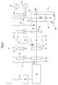
- Fig. 1 shows a drive device for driving Additional equipment for a vehicle.
- a vehicle can for example, an agricultural or industrial Commercial vehicle, preferably it could be a tractor act.
- An internal combustion engine 18 is via a drive shaft 38 connected to a mixing gear 10.
- the mixing gear 10 is connected to a PTO shaft 14, with the accessories for the vehicle can be driven.
- An electric Machine 12 is also connected to the mixing gear 10.
- the drive device comprises at least one Mixing gear 10, an electric machine 12 and a PTO 14.
- a transmission interface 16 of the mixing gear 10 is of the internal combustion engine 18, in particular a diesel engine, driven.
- the electric machine 12 is provided with a second one Gear interface 20 of the mixing gear 10 connected.
- the PTO 14 is connected to a third transmission interface 22nd the mixing gear 10 in conjunction.
- the further electric machine 36 has preferably a nominal power of about 20 kW.
- the rated power the electric machine 12 is preferably about 30 kW, that of the internal combustion engine 18 preferably about 100 kW.
- Both the electric machine 12 and the other Electric machine 36 is operable as a generator. Furthermore, the electric machine 12 or the other electric machine 36 operable as an electric motor.
- the electric machine 12 and the other electrical Machine 36 is associated with a respective inverter 40, with the the respective electric machine 12, 36 in both Turning directions and / or torque directions can be switched, so that a four-quadrant operation of the electric machines 12, 36 is possible.
- controller 42 which controls the internal combustion engine 18, the electric machine 12, the more electric Machine 36, the inverter 40 and the brake 24 drives.
- the Control 42 may be connected to the vehicle via a bus system of the vehicle individual components connected, which is due to the elongated Form of the controller 42 is indicated in Fig. 1.
- the state data of the internal combustion engine 18, the PTO shaft 14, the electric machine 12 and the other electrical Machine 36 can be detected by the controller 42.
- a speed sensor 46 on the PTO 14th provided which generates a speed signal and the controller 42 zuRIC via the connecting line 48.
- the status data of the internal combustion engine 18 are the controller 50 of Internal combustion engine 18 known and the controller 42 via the connecting line 52 is supplied.
- a Speed sensor 49 is provided, the speed of the Motor output shaft 38 detected, generates a speed signal and this the controller 42 via the connection line 51st feeds.
- the status data of the two electrical machines 12, 36 are the controller 42 due to the of the converters 40 generated electrical state variables known over the Connecting lines 54 are connected to the controller 42.
- a speed sensor 44 is provided which the Speed and the direction of rotation of the second gear interface 20 and thus the speed and direction of rotation electrical machine 12 detected and the controller 42nd reports.
- the speed sensor 44 is via the connection line 45 connected to the controller 42.
- the electric machine 12 In PTO mode, ie with open brake 24, the electric machine 12, the further electric machine 36 and the mixing gear 10 to a power split stepless Gearbox for PTO 14 can be combined.
- the brake 24 is provided by an electrical drive element 56 operated.
- the power supply receives this Control element 56 via a DC network 58, in which also the electrical machines 12, 36 their generated electrical Feed energy or from which the electrical machines 12, 36 are supplied with electrical energy, depending on whether they are operated as a generator and / or as an electric motor.
- the electrical drive element 56 is over the Connecting line 60 driven by the controller 42.
- the electric machine 12 can operate as a generator and supply an electrical consumer in this case, For example, one to an electrical interface 63rd connectable, not shown electrical loads.
- the interface 63 could be in the form of a power outlet be executed.
- the interface 63 is controlled by a controller 65 electrically supplied via the connecting line 67.
- These Interface provides AC power to the utility Available, assigned by one of the controller 65 - not disconnected - inverter from the over the DC mains 58 is generated related DC.
- the consumer DC power directly from the DC network 58 provides.
- the generated by the electric machine 12 electrical energy is supplied to a braking resistor 69, which converts them into heat.
- a switch 71 of the controller 42 connected to the braking resistor 69 with the DC network 58 to connect.
- FIG. 2 shows a Drive device according to the invention, in a agricultural utility vehicle is installed.
- FIG. 2 becomes like components with the same Reference number assigned.
- the vehicle has two by an electric motor 64th driven vehicle wheels 66 on. At the vehicle wheels 66 it concerns vehicle wheels of a front axle of the Vehicle.
- the required for the two electric motors 64 electrical energy is either from the electrical Machine 12 or from the further electric machine 36 generated and via the DC network 58 via the inverter 40th provided to the electric motors 64.
- the the Electric motors 64 associated with inverter 40 are on the Connecting lines 72 connected to the controller 42.
- the two electric motors 64 may also be a single Be provided electric motor, the two vehicle wheels of the Front axle drives.
- vehicle wheels 68 are one Rear axle of the vehicle provided, via a transmission 70th connected to the internal combustion engine.
- speed sensor 46 for the PTO 14 In addition to the speed sensor 46 for the PTO 14 are four further speed sensors 74 are provided, each of which Speed of the vehicle wheels 66 and 68 detect.
- Speed sensor 76 detects the speed of the Motor output shaft 38 and thus the speed of the Internal combustion engine 18.
- the connecting lines 78 and 80 respectively connect the speed sensors 74 and 76 to the controller 42nd
- FIG. 3 shows an exemplary embodiment of a mixing gear 10 of the present invention.
- the mixing gear 10 is as Planetary gear executed.
- the planetary gear includes a Ring gear 26, which via the transmission interface 16 from - in Fig. 3, not shown - internal combustion engine is driven.
- the sun gear 28 of the planetary gear is with the - in Fig. 3rd also not shown - connected electrical machine.
- the PTO not shown in Fig. 3 is connected to the Planet carrier 30 connected, wherein on the Planetary 30 preferably three Step planet gears 32, 34 are arranged, which respectively have two gears with different diameters.
- the gears 32 of smaller diameter, the Gears 34 of larger diameter and the sun gear 28th Behavior is at a speed of the engine 18th of +2000 revolutions per minute and with engaged brake 24 and thus at shutdown PTO 14, the electrical Machine 12 with a speed of - 3000 revolutions per Minute driven.
- the electric machine 12 is so compared to the internal combustion engine 18 translated into quick what favorable for a power output of the electric Machine 12 affects when it is operating in generator mode.
- a PTO speed of Be required 1000 revolutions per minute.
- a PTO speed of Be required 1000 revolutions per minute.
- a PTO speed of Be required 1000 revolutions per minute.
- At one speed of the internal combustion engine 18 of +2000 revolutions per minute is a given speed of the engine operated electric machine 12 from - 500 revolutions per minute required.
- the translation of the mixing gear 10 is thus such designed that the main working area of the PTO 14th Required speeds in the optimum efficiency speed range of the internal combustion engine 18, and that a comparatively small power component of the electric machine 12 is to provide.
- FIG. 4 shows a development of the first Embodiment of FIG. 1, which is a switchable Has spur gear 82.
- the switchable Spur gear 82 includes two connected to the shaft 84 Spur gears 86, wherein the left-hand spur 86th a compared to the right-hand spur gear 86th larger diameter.
- the spur gears 86 comb in each case a switchable spur gear 88, wherein the left drawn spur gear 88 a compared to the right has shown spur gear 88 smaller diameter.
- the switchable spur gears 88 can from a Switching device 90 are switched accordingly, so that the torque transmitted by the shaft 84 either via the both on the left or above the two on the right Spur gears 86, 88 is transmitted to the PTO 14.
- the Switching device 90 is from the controller 42 via the Connection line 92 driven by the controller 94.
- the switchable spur gear 82 of FIG. 4 is also to the PTO shaft 14 of the second embodiment of FIG. 2 accordingly connectable.
- Fig. 5 shows a schematic representation of a Further development of the embodiment of FIG. 4 or a More detailed view of mixed transmission 10 taking shape a positive gear is executed.
- the mixing gear 10 off Fig. 5 has two sun gears 96, 98 and more in one Planet carrier 100 circumferential stepped planet gears 102 on.
- the rotor or rotor 106 of the electric machine 12 is with the second designed in the form of a sun gear 96 Gear interface 20 connected.
- the stator 108 of the Electric machine 12 is at a - not shown - Housing arranged.
- the internal combustion engine 18 is over the Transmission 70 and the transmission interface 16 with the Planet carrier 100 of the mixing gear 10 connected.
- the PTO 14 is in the form of a hollow shaft and the second sun gear 98 formed third Gear interface 22 in conjunction, via the switchable spur gear 82.
- the spur gear 82 includes the meshing with each other spur gears 110, 112 and the meshing with each other spur gears 114, 116.
- the Switching device 118 may either the spur gears 110, 112 with the PTO 14 or the spur gears 114, 116 with the PTO 14 are rotatably connected.
- the spur wheels 110, 114 are rotatably with the hollow shaft, thus with the second sun gear 98 connected.
- the switching device 118 it is a positive coupling, which is switched electromechanically. Only schematic with the reference numeral 120, the connection lines between the electrical machines 12, 36 and the - in Figs. 5 and 6 not shown - control 42 indicated.
- Fig. 6 shows an embodiment of the invention, with a to that of FIG. 5 substantially similar construction.
- the electric machine 12 and its rotor 106 formed in the form of a hollow rotor.
- the mixing gear 10 is in the form of a hollow rotor 106 of the rotor electrical machine 12 is arranged.
- the rotor 106 of the electric machine 12 of FIG. 6 via the second transmission interface 20 with the sun gear 96th connected.
- the mixing gear 10 and the electric machine 12 together in a housing - in Fig. 6 not shown - arranged.
- the electrical Machine 12 is first the mixing gear 10 for lubrication Supplied with oil.
- the oil passes over in Fig. 6, not shown Connection openings in the interior of the rotor 106 of the electric machine 12, wherein on the interior of the rotor 106 of the electric machine 12 laterally arranged discs 104 are provided, which is a drainage of the coolant in prevent axial direction at least largely.
- passages 122 extend in the radial direction and in particular Slots and / or holes in the rotor have. to clearer representation in Fig. 6 fewer passages 122nd marked as actually provided and the Diameter of the bores or the passages 122 are shown enlarged. With the flowed out oil can then the stator 108 of the electric machine 12 also be cooled.
- the electric machine 12 of FIGS. 5 and 6 each has an asynchronous machine.
Landscapes
- Engineering & Computer Science (AREA)
- Mechanical Engineering (AREA)
- Transportation (AREA)
- Chemical & Material Sciences (AREA)
- Combustion & Propulsion (AREA)
- Power Engineering (AREA)
- Life Sciences & Earth Sciences (AREA)
- Soil Sciences (AREA)
- Environmental Sciences (AREA)
- Electric Propulsion And Braking For Vehicles (AREA)
- Agricultural Machines (AREA)
- Hybrid Electric Vehicles (AREA)
- Arrangement And Driving Of Transmission Devices (AREA)
Abstract
Description
- Fig. 1
- die schematische Darstellung eines ersten Ausführungsbeispiels der vorliegenden Erfindung,
- Fig. 2
- die schematische Darstellung eines zweiten Ausführungsbeispiels der vorliegenden Erfindung,
- Fig. 3
- die schematische Darstellung eines Ausführungsbeispiels eines Mischgetriebes gemäß der vorliegenden Erfindung,
- Fig. 4
- eine schematische Darstellung einer Weiterbildung des ersten Ausführungsbeispiels der vorliegenden Erfindung,
- Fig. 5
- eine schematische Darstellung einer Weiterbildung des Ausführungsbeispiels aus Fig. 4 der vorliegenden Erfindung und
- Fig. 6
- eine schematische Darstellung einer Alternative des Ausführungsbeispiels aus Fig. 5 der vorliegenden Erfindung.
Claims (24)
- Antriebsvorrichtung zum Antreiben von Zusatzgeräten für ein Fahrzeug, insbesondere ein landwirtschaftliches oder industrielles Nutzfahrzeug, mit einem Mischgetriebe (10), einer elektrischen Maschine (12) und einer Zapfwelle (14), wobei eine Getriebeschnittstelle (16) des Mischgetriebes (10) von einem Verbrennungsmotor (18) antreibbar ist und wobei die elektrische Maschine (12) mit einer zweiten Getriebeschnittstelle (20) des Mischgetriebes (10) in Verbindung steht, dadurch gekennzeichnet, dass die Zapfwelle (14) mit einer dritten Getriebeschnittstelle (22) des Mischgetriebes (10) in Verbindung steht.
- Antriebsvorrichtung nach Anspruch 1, dadurch gekennzeichnet, dass das Mischgetriebe (10) ein Umlaufgetriebe aufweist.
- Antriebsvorrichtung nach Anspruch 1 oder 2, dadurch gekennzeichnet, dass eine Bremse (24) vorgesehen ist, mit der die Zapfwelle (14) stillsetzbar ist.
- Antriebsvorrichtung nach einem der vorhergehenden Ansprüche, dadurch gekennzeichnet, dass eine weitere elektrische Maschine (36) vorgesehen ist, die mittelbar oder unmittelbar von einem Verbrennungsmotor (18) antreibbar ist, wobei vorzugsweise die elektrische Maschine (12) und/oder die weitere elektrische Maschine (36) als Generator betreibbar ist bzw. sind.
- Antriebsvorrichtung nach einem der vorhergehenden Ansprüche, dadurch gekennzeichnet, dass die elektrische Maschine (12) und/oder die weitere elektrische Maschine (36) als Elektromotor betreibbar ist.
- Antriebsvorrichtung nach einem der vorhergehenden Ansprüche, dadurch gekennzeichnet, dass der elektrischen Maschine (12) und/oder der weiteren elektrischen Maschine (36) jeweils ein Umrichter (40) zugeordnet ist, mit dem die jeweilige elektrische Maschine (12, 36) in beide Drehrichtungen und/oder Drehmomentrichtungen schaltbar ist.
- Antriebsvorrichtung nach einem der vorhergehenden Ansprüche, dadurch gekennzeichnet, dass eine Steuerung (42) vorgesehen ist, die den Verbrennungsmotor (18), die elektrische Maschine (12), die weitere elektrische Maschine (36), mindestens einen Umrichter (40) und/oder die Bremse (24) ansteuert, und dass vorzugsweise Zustandsdaten des Verbrennungsmotors (18), der Zapfwelle (14), der elektrischen Maschine (12) und/oder der weiteren elektrischen Maschine (36) von der Steuerung (42) erfassbar sind, insbesondere über Sensoren.
- Antriebsvorrichtung nach einem der vorhergehenden Ansprüche, dadurch gekennzeichnet, dass bei geöffneter Bremse (24) die elektrische Maschine (12), die weitere elektrische Maschine (36) und das Mischgetriebe (10) zu einem leistungsverzweigten stufenlosen Getriebe für die Zapfwelle (14) kombinierbar ist, dass vorzugsweise die weitere elektrische Maschine (36) als Generator betreibbar ist und dass vorzugsweise die elektrische Maschine (12) als Elektromotor betreibbar ist.
- Antriebsvorrichtung nach Anspruch 7 oder 8, dadurch gekennzeichnet, dass die Steuerung (42), die elektrische Maschine (12) und gegebenenfalls die weitere elektrische Maschine (36) derart ansteuert, dass wenigstens ein in der Steuerung (42) hinterlegtes vorgebbares Optimierungsziel erreichbar ist, beispielsweise der niedrigste Kraftstoffverbrauch des Verbrennungsmotors (18) und/oder die geringst mögliche Geräuschentwicklung.
- Antriebsvorrichtung nach einem der Ansprüche 7 bis 9 dadurch gekennzeichnet, dass die Steuerung (42), die elektrische Maschine (12) und/oder gegebenenfalls die weitere elektrische Maschine (36) derart ansteuert, dass Drehschwingungen in einem Zapfwellenstrang dämpfbar sind.
- Antriebsvorrichtung nach einem der vorhergehenden Ansprüche, dadurch gekennzeichnet, dass die Übersetzung des Mischgetriebes (10) derart ausgelegt ist, dass die im Hauptarbeitsbereich der Zapfwelle (14) benötigten Drehzahlen im wirkungsgradoptimalen Drehzahlbereich des Verbrennungsmotors (18) liegen, und dass vorzugsweise ein minimaler Leistungsanteil der elektrischen Maschine (12) und/oder der weiteren elektrischen Maschine (36) bereitzustellen ist.
- Antriebsvorrichtung nach einem der vorhergehenden Ansprüche, dadurch gekennzeichnet, dass das Drehmoment der Zapfwelle (14) anhand des von der elektrischen Maschine (12) erzeugten Drehmoments bestimmbar ist.
- Antriebsvorrichtung nach einem der Ansprüche 3 bis 12, dadurch gekennzeichnet, dass die elektrische Maschine (12) und die weitere elektrische Maschine (36) räumlich nah beieinander angeordnet sind, und dass vorzugsweise beide elektrische Maschinen (12, 36) von einer Kühleinrichtung (62) kühlbar sind.
- Antriebsvorrichtung nach einem der vorhergehenden Ansprüche, dadurch gekennzeichnet, dass die elektrische Maschine (12) und/oder die weitere elektrische Maschine (36) jeweils als Generator arbeitet und einen elektrischen Verbraucher versorgt bzw. versorgen, beispielsweise einen elektrischen Heizwiderstand oder einen an eine elektrische Schnittstelle (63) anschließbaren elektrischen Verbraucher.
- Antriebsvorrichtung nach einem der vorhergehenden Ansprüche, dadurch gekennzeichnet, dass zwischen der Zapfwelle (14) und der dritten Getriebeschnittstelle (22) eine Stirnradstufe vorgesehen ist, die vorzugsweise schaltbar ausgeführt ist und zur Umschaltung zwischen zwei unterschiedlichen Drehzahlen der Zapfwelle (14) dient.
- Antriebsvorrichtung nach einem der vorangegangenen Ansprüche, dadurch gekennzeichnet, dass das Mischgetriebe (10) ein Plusgetriebe aufweist, welches vorzugsweise zwei Sonnenräder (96, 98) und mehrere in einem Planetenträger (100) umlaufende Stufenplanetenräder (102) aufweist, wobei die elektrische Maschine (12) mit der in Form eines Sonnenrads (96) ausgeführten zweiten Getriebeschnittstelle (20) verbunden ist, wobei der Verbrennungsmotor (18) - insbesondere über einen Steg - mit der Getriebeschnittstelle (16) - vorzugsweise einem Planetenträger (100) des Mischgetriebes (10) - verbindbar ist und wobei die Zapfwelle (14) mit der in Form eines zweiten Sonnenrads (98) ausgeführten dritten Getriebeschnittstelle (22) in Verbindung steht.
- Antriebsvorrichtung nach einem der vorangegangenen Ansprüche, dadurch gekennzeichnet, dass die elektrische Maschine (12) im Inneren in Form eines Hohlläufers ausgebildet ist und dass das Mischgetriebe (10) zumindest teilweise in der elektrischen Maschine (12) angeordnet ist.
- Antriebsvorrichtung nach einem der vorangegangenen Ansprüche, dadurch gekennzeichnet, dass die elektrische Maschine (12) eine Asynchronmaschine aufweist.
- Antriebsvorrichtung nach Anspruch 17 oder 18, dadurch gekennzeichnet, dass Kühlmittel - insbesondere Öl - zunächst dem Mischgetriebe (10) zur Schmierung zugeführt wird, welches in den Innenraum des Rotors (106) der elektrischen Maschine (12) gelangt, wobei vorzugsweise an dem Innenraum des Rotors (106) der elektrischen Maschine (12) Mittel vorgesehen sind, welche insbesondere seitlich angeordnete Scheiben (104) aufweisen, und welche ein Abfließen des Kühlmittels in axialer Richtung zumindest weitgehend verhindern.
- Antriebsvorrichtung nach Anspruch 19, dadurch gekennzeichnet, dass zur Kühlung des Rotors (106) das bei Rotation des Rotors (106) der elektrischen Maschine (12) aufgrund der Fliehkraft nach außen geschleuderte Kühlmittel durch Durchgänge (122) nach außen fließt, wobei die Durchgänge (122) sich im Wesentlichen in radialer Richtung erstrecken und insbesondere Schlitze und/oder Bohrungen in den beiden Kurzschlussringen des Rotors (106) aufweisen können, und dass vorzugsweise der Stator (108) der elektrischen Maschine (12) - insbesondere die Wickelköpfe - ebenfalls gekühlt werden kann.
- Fahrzeug, insbesondere ein landwirtschaftliches oder ein industrielles Nutzfahrzeug, gekennzeichnet durch eine Antriebsvorrichtung nach einem der Ansprüche 1 bis 20, wobei vorzugsweise eine Drehzahlregelung der Zapfwelle (14) vorgesehen ist, die abhängig von der Fahrzeuggeschwindigkeit ist.
- Fahrzeug nach Anspruch 21, dadurch gekennzeichnet, dass die elektrische Maschine (12) und/oder die weitere elektrische Maschine (36) zur Bremsung des Fahrzeugs, insbesondere zur Dauerbremsung, konfigurierbar ist bzw. sind.
- Fahrzeug nach Anspruch 21 oder 22, dadurch gekennzeichnet, dass das Fahrzeug mindestens ein durch einen Elektromotor (64) angetriebenes Fahrzeugrad (66) aufweist und dass die von der elektrischen Maschine (12) und/oder der weiteren elektrischen Maschine (36) erzeugte elektrische Energie den Elektromotor (64) des Fahrzeugrads (66) speist.
- Fahrzeug nach einem der Ansprüche 21 bis 23, dadurch gekennzeichnet, dass während des reinen Fahrbetriebs des Fahrzeugs die Zapfwelle (14) mit der Bremse (24) stillgesetzt ist.
Priority Applications (2)
| Application Number | Priority Date | Filing Date | Title |
|---|---|---|---|
| DE102004049795A DE102004049795A1 (de) | 2004-04-08 | 2004-10-12 | Kühlvorrichtung für eine mit einer Kühlflüssigkeit kühlbaren elektrischen Maschine |
| PCT/EP2005/051533 WO2005099070A1 (de) | 2004-04-08 | 2005-04-06 | Kühlvorrichtung für eine mit einer kühlflüssigkeit kühlbaren elektrischen maschine |
Applications Claiming Priority (2)
| Application Number | Priority Date | Filing Date | Title |
|---|---|---|---|
| DE10315937A DE10315937A1 (de) | 2003-04-08 | 2003-04-08 | Antriebsvorrichtung zum Antreiben von Zusatzgeräten für ein Fahrzeug |
| DE10315937 | 2003-04-08 |
Publications (3)
| Publication Number | Publication Date |
|---|---|
| EP1466773A2 true EP1466773A2 (de) | 2004-10-13 |
| EP1466773A3 EP1466773A3 (de) | 2006-06-21 |
| EP1466773B1 EP1466773B1 (de) | 2013-01-16 |
Family
ID=32864366
Family Applications (1)
| Application Number | Title | Priority Date | Filing Date |
|---|---|---|---|
| EP04101458A Expired - Lifetime EP1466773B1 (de) | 2003-04-08 | 2004-04-08 | Antriebsvorrichtung zum Antreiben von Zusatzgeräten für ein Fahrzeug |
Country Status (4)
| Country | Link |
|---|---|
| US (1) | US7311627B2 (de) |
| EP (1) | EP1466773B1 (de) |
| BR (1) | BRPI0401036B1 (de) |
| DE (1) | DE10315937A1 (de) |
Cited By (3)
| Publication number | Priority date | Publication date | Assignee | Title |
|---|---|---|---|---|
| WO2007031397A1 (de) * | 2005-09-15 | 2007-03-22 | Deere & Company | Antriebssystem für ein landwirtschaftliches oder industrielles nutzfahrzeug und verfahren zum betreiben eines antriebssystems |
| WO2007031399A1 (de) * | 2005-09-15 | 2007-03-22 | Deere & Company | Antriebssystem für ein landwirtschaftliches oder industrielles nutzfahrzeug |
| WO2012090019A1 (en) * | 2010-12-30 | 2012-07-05 | Renault Trucks | Dual drive arrangement for the drive of a vehicle hydraulic pump and method of controlling the same |
Families Citing this family (45)
| Publication number | Priority date | Publication date | Assignee | Title |
|---|---|---|---|---|
| JP2006273514A (ja) | 2005-03-29 | 2006-10-12 | Toyota Industries Corp | ハイブリッド型フォークリフト |
| DE102005044181A1 (de) * | 2005-09-15 | 2007-04-19 | Deere & Company, Moline | Antriebssystem für ein Fahrzeug und ein landwirtschaftliches Nutzfahrzeug |
| DE102006011993A1 (de) * | 2006-03-16 | 2007-09-20 | Agrarsystem Gmbh | Regelkreisantrieb für ein Arbeitsaggregat einer landwirtschaftlichen oder einer kommunalen Maschine oder einer Baumaschine |
| KR100802692B1 (ko) * | 2006-08-08 | 2008-02-12 | 현대자동차주식회사 | 하이브리드 전기 자동차의 동력전달장치 |
| US7556578B2 (en) * | 2006-10-26 | 2009-07-07 | Gm Global Technology Operations, Inc. | Method and apparatus to control operation of a hydraulic control circuit for an electro-mechanical transmission |
| JP5327475B2 (ja) * | 2007-10-31 | 2013-10-30 | トヨタ自動車株式会社 | 搬送用自走車及びその停止制御方法 |
| US20100236207A1 (en) * | 2009-03-23 | 2010-09-23 | Deere & Company | Slurry transport system for forage harvester |
| US8602135B2 (en) * | 2009-06-25 | 2013-12-10 | Deere & Company | Drive quad module |
| WO2011010182A1 (en) | 2009-07-22 | 2011-01-27 | Renault Trucks | Drive arrangement for vehicle auxiliaries |
| US8763737B2 (en) * | 2009-08-20 | 2014-07-01 | Deere & Company | Powertrain cooling circuit |
| DE102010009874A1 (de) * | 2010-02-23 | 2011-08-25 | Dr. Ing. h.c. F. Porsche Aktiengesellschaft, 70435 | Antriebsstrang eines Kraftfahrzeugs |
| EP2551140B1 (de) * | 2011-07-27 | 2018-04-25 | CLAAS Tractor S.A.S. | Landwirtschaftsfahrzeug und Betriebsverfahren |
| JP2013056629A (ja) * | 2011-09-08 | 2013-03-28 | Kanzaki Kokyukoki Manufacturing Co Ltd | 作業車両のハイブリッド駆動システム |
| DE102012006189A1 (de) | 2012-03-27 | 2013-10-02 | Bomag Gmbh | Antriebsvorrichtung in einer selbstfahrenden Baumaschine sowie Verfahren zum Einstellen eines Drehzahlverhältnisses bei einer derartigen Antriebsvorrichtung |
| DE102012216464A1 (de) * | 2012-09-14 | 2014-03-20 | Bombardier Transportation Gmbh | Betrieb eines Schienen-Triebfahrzeuges mit einer Mehrzahl von Brennkraftmaschinen |
| DE102013211813A1 (de) * | 2013-06-21 | 2014-07-31 | Schaeffler Technologies Gmbh & Co. Kg | Zusatzantrieb für ein Nebenaggregat und Verfahren zum Betrieb des Zusatzantriebs |
| US10655710B2 (en) | 2013-12-31 | 2020-05-19 | Deere & Company | Multi-mode infinitely variable transmission that provides seamless shifting |
| US10670124B2 (en) | 2013-12-31 | 2020-06-02 | Deere & Company | Multi-mode infinitely variable transmission |
| US10647193B2 (en) | 2014-04-09 | 2020-05-12 | Deere & Company | Multi-mode power trains |
| US10738868B2 (en) | 2014-04-09 | 2020-08-11 | Deere & Company | Multi-mode powertrains |
| DE102016011318B4 (de) | 2015-09-24 | 2018-10-04 | Ursula Kalinowski-Krumm | Antriebsstrang einer mobilen Arbeitsmaschine mit einem Leistungsverzweigungsgetriebe mit zusätzlicher, fahrzeugunabhängiger Energiezuführung oder -abführung |
| DE102015013542B4 (de) * | 2015-10-19 | 2019-03-21 | Audi Ag | Antriebsstrang eines Kraftfahrzeugs und Kraftfahrzeug |
| US10183661B2 (en) | 2016-07-22 | 2019-01-22 | Deere & Company | Variable power take-off with electric generating capacity |
| DE102016218159A1 (de) | 2016-09-21 | 2018-03-22 | Zf Friedrichshafen Ag | Antriebsanordnung mit einer leistungsverzweigten Getriebevorrichtung |
| DE102016221311A1 (de) * | 2016-10-28 | 2018-05-03 | Deere & Company | Landwirtschaftliches Nutzfahrzeug mit Zapfwelle und Verfahren zum Antrieb der Zapfwelle |
| DE102017205149A1 (de) * | 2017-03-27 | 2018-09-27 | Zf Friedrichshafen Ag | Antriebsanordnung mit einem Zapfwellengetriebe |
| US10619711B2 (en) | 2017-04-12 | 2020-04-14 | Deere & Company | Infinitely variable transmission with power reverser |
| US11052747B2 (en) | 2018-05-04 | 2021-07-06 | Deere & Company | Multi-mode powertrains |
| US11091018B2 (en) | 2018-05-11 | 2021-08-17 | Deere & Company | Powertrain with variable vertical drop distance |
| US10975959B2 (en) | 2019-04-01 | 2021-04-13 | Deere & Company | Transmission clutch braking control system |
| US11137052B2 (en) | 2019-08-29 | 2021-10-05 | Deere & Company | Transmission assembly with integrated CVP |
| US11351983B2 (en) | 2019-10-31 | 2022-06-07 | Deere & Company | Power control system with transmission transient boost function |
| DE102019130113A1 (de) * | 2019-11-07 | 2021-05-12 | Kessler energy GmbH | Antriebseinheit für ein nutzfahrzeug |
| US11846085B2 (en) | 2020-02-17 | 2023-12-19 | Deere & Company | Energy management system for a hybrid vehicle with an electrically powered hydraulic system |
| US11926209B2 (en) * | 2020-02-19 | 2024-03-12 | Deere & Company | Electric power take off |
| US11325459B2 (en) | 2020-10-09 | 2022-05-10 | Deere & Company | Low profile transmission assembly with integrated CVP |
| SE544919C2 (en) * | 2020-10-21 | 2023-01-03 | Scania Cv Ab | Control device and method of controlling a vehicle powertrain comprising a power take-off |
| US11613246B2 (en) | 2021-01-21 | 2023-03-28 | Deere & Company | Power control system with engine throttle shift function |
| US11628822B2 (en) | 2021-02-09 | 2023-04-18 | Deere & Company | Power control system with stall prevention clutch modulation function |
| US11299141B1 (en) | 2021-02-10 | 2022-04-12 | Deere & Company | System for multi-layer braking and retardation in a work vehicle |
| DE102021211811B3 (de) * | 2021-10-20 | 2023-01-19 | Zf Friedrichshafen Ag | Leistungsstrang für eine Elektromaschine einer Arbeitsmaschine |
| US11820361B2 (en) | 2021-11-30 | 2023-11-21 | Deere & Company | Transmission assembly with electrical machine unit for improved shift quality |
| US11607948B1 (en) | 2021-12-22 | 2023-03-21 | Deere & Company | Electronically-variable power shift transmission for work vehicles |
| US11585412B1 (en) | 2021-12-22 | 2023-02-21 | Deere & Company | Electronically-variable, dual-path power shift transmission for work vehicles |
| US11913528B1 (en) | 2022-10-28 | 2024-02-27 | Deere & Company | Multi-mode continuously variable transmission assembly with drop set arrangement |
Citations (3)
| Publication number | Priority date | Publication date | Assignee | Title |
|---|---|---|---|---|
| DE19749074A1 (de) | 1997-11-06 | 1999-05-20 | Roland Dr Schmetz | Landwirtschaftliches Nutzfahrzeug mit mechanisch-elektrisch leistungsverzweigtem Getriebe |
| US6052978A (en) | 1998-03-21 | 2000-04-25 | Deere & Company | Ensilage harvester variable speed feed roll drive |
| EP1293697A2 (de) | 2001-09-15 | 2003-03-19 | Deere & Company | Verfahren und Vorrichtung zur Steuerung einer Kupplung |
Family Cites Families (25)
| Publication number | Priority date | Publication date | Assignee | Title |
|---|---|---|---|---|
| DE59309163D1 (de) | 1992-09-12 | 1999-01-07 | Schlattl Werner Bavaria Tech | Antriebsaggregat mit variator, insbesondere für fahrzeuge |
| DE19526184A1 (de) * | 1995-07-18 | 1997-04-03 | Siemens Ag | Verfahren zur Herstellung eines MOS-Transistors |
| US5577973A (en) * | 1995-07-20 | 1996-11-26 | General Motors Corporation | Two-mode, split power, electro-mechanical transmission |
| US5669842A (en) | 1996-04-29 | 1997-09-23 | General Motors Corporation | Hybrid power transmission with power take-off apparatus |
| US5730676A (en) * | 1996-10-22 | 1998-03-24 | General Motors Corporation | Three-mode, input-split hybrid transmission |
| US6030874A (en) * | 1997-01-21 | 2000-02-29 | Texas Instruments Incorporated | Doped polysilicon to retard boron diffusion into and through thin gate dielectrics |
| JPH10217784A (ja) * | 1997-02-07 | 1998-08-18 | Kanzaki Kokyukoki Mfg Co Ltd | トラクタの動力取出し装置 |
| JP3262046B2 (ja) * | 1997-09-17 | 2002-03-04 | トヨタ自動車株式会社 | ギヤ機構における歯打ち音の低減方法、動力出力装置およびこの動力出力装置を搭載したハイブリッド車輌 |
| US6146302A (en) * | 1997-12-26 | 2000-11-14 | Fuji Jukogyo Kabushiki Kaisha | Power transmitting system for a hybrid motor vehicle |
| US6045485A (en) * | 1998-07-29 | 2000-04-04 | Navistar International Transportation Corp. | Circuit for interfacing vehicle drivetrain, service brake, and power take-off with engine control |
| US6160300A (en) * | 1999-01-26 | 2000-12-12 | Advanced Micro Devices, Inc. | Multi-layer gate conductor having a diffusion barrier in the bottom layer |
| US6173225B1 (en) * | 1999-04-20 | 2001-01-09 | Case Corporation | Power takeoff control system |
| ITBO20000648A1 (it) * | 2000-11-09 | 2002-05-09 | New Holland Italia Spa | Apparecchiatura di comando del regime di un mezzo semovente |
| US6579202B2 (en) * | 2000-12-18 | 2003-06-17 | General Motors Corporation | Lubrication and cooling system for power receiving and delivery units in an electro-mechanical vehicular transmission |
| US6455947B1 (en) * | 2001-02-14 | 2002-09-24 | Bae Systems Controls, Inc. | Power combining apparatus for hybrid electric vehicle |
| US6988571B2 (en) * | 2001-04-04 | 2006-01-24 | Eiichi Okamoto | Crawler tractor |
| US6376323B1 (en) * | 2001-04-04 | 2002-04-23 | Advanced Micro Devices, Inc. | Fabrication of gate of P-channel field effect transistor with added implantation before patterning of the gate |
| FR2824509B1 (fr) * | 2001-05-11 | 2003-08-22 | Renault | Dispositif de traction du type "hybride parallele", notamment pour vehicule automobile |
| JP3707411B2 (ja) * | 2001-09-28 | 2005-10-19 | トヨタ自動車株式会社 | 動力出力装置およびこれを備える自動車 |
| US6551208B1 (en) * | 2001-10-18 | 2003-04-22 | General Motors Corporation | Three-mode, compound-split, electrically-variable transmission |
| JP3547735B2 (ja) * | 2001-11-22 | 2004-07-28 | 本田技研工業株式会社 | エンジンシステムとその運転方法およびエンジン始動装置 |
| US6692395B2 (en) * | 2002-02-25 | 2004-02-17 | Deere & Company | Transmisson for power take-off |
| US6662890B2 (en) * | 2002-02-26 | 2003-12-16 | General Motors Corporation | Vehicle transmission with a fuel cell power source and a multi-range transmission |
| JP3650089B2 (ja) * | 2002-08-02 | 2005-05-18 | トヨタ自動車株式会社 | ハイブリッド駆動装置並びにそれを搭載した自動車 |
| US20060021455A1 (en) * | 2003-04-25 | 2006-02-02 | Seipold John M | Power takeoff assembly and method |
-
2003
- 2003-04-08 DE DE10315937A patent/DE10315937A1/de not_active Ceased
-
2004
- 2004-02-25 US US10/786,534 patent/US7311627B2/en not_active Expired - Fee Related
- 2004-04-07 BR BRPI0401036A patent/BRPI0401036B1/pt active IP Right Grant
- 2004-04-08 EP EP04101458A patent/EP1466773B1/de not_active Expired - Lifetime
Patent Citations (3)
| Publication number | Priority date | Publication date | Assignee | Title |
|---|---|---|---|---|
| DE19749074A1 (de) | 1997-11-06 | 1999-05-20 | Roland Dr Schmetz | Landwirtschaftliches Nutzfahrzeug mit mechanisch-elektrisch leistungsverzweigtem Getriebe |
| US6052978A (en) | 1998-03-21 | 2000-04-25 | Deere & Company | Ensilage harvester variable speed feed roll drive |
| EP1293697A2 (de) | 2001-09-15 | 2003-03-19 | Deere & Company | Verfahren und Vorrichtung zur Steuerung einer Kupplung |
Cited By (6)
| Publication number | Priority date | Publication date | Assignee | Title |
|---|---|---|---|---|
| WO2007031397A1 (de) * | 2005-09-15 | 2007-03-22 | Deere & Company | Antriebssystem für ein landwirtschaftliches oder industrielles nutzfahrzeug und verfahren zum betreiben eines antriebssystems |
| WO2007031399A1 (de) * | 2005-09-15 | 2007-03-22 | Deere & Company | Antriebssystem für ein landwirtschaftliches oder industrielles nutzfahrzeug |
| US8469127B2 (en) | 2005-09-15 | 2013-06-25 | Deere & Company | Drive system for an agricultural or industrial utility vehicle and method for operating a drive system |
| WO2012090019A1 (en) * | 2010-12-30 | 2012-07-05 | Renault Trucks | Dual drive arrangement for the drive of a vehicle hydraulic pump and method of controlling the same |
| JP2014502934A (ja) * | 2010-12-30 | 2014-02-06 | ルノー・トラックス | 自動車油圧ポンプを駆動させるデュアル駆動機構及びその制御方法 |
| US9162571B2 (en) | 2010-12-30 | 2015-10-20 | Volvo Trucks AB | Dual drive arrangement for the drive of a vehicle hydraulic pump and method of controlling the same |
Also Published As
| Publication number | Publication date |
|---|---|
| BRPI0401036B1 (pt) | 2016-08-23 |
| US7311627B2 (en) | 2007-12-25 |
| US20040204276A1 (en) | 2004-10-14 |
| BRPI0401036A (pt) | 2005-05-17 |
| EP1466773A3 (de) | 2006-06-21 |
| EP1466773B1 (de) | 2013-01-16 |
| DE10315937A1 (de) | 2004-11-11 |
Similar Documents
| Publication | Publication Date | Title |
|---|---|---|
| EP1466773A2 (de) | Antriebsvorrichtung zum Antreiben von Zusatzgeräten für ein Fahrzeug | |
| EP3006245B1 (de) | Getriebesteuerverfahren | |
| DE60305549T2 (de) | Steuerungssystem für Hybridfahrzeuge | |
| EP1926620B1 (de) | Antriebssystem für ein fahrzeug und ein landwirtschaftliches nutzfahrzeug | |
| DE102006060401B4 (de) | Fahrzeugantriebssystem | |
| EP1409282B1 (de) | Verfahren zum betrieb eines von einem verbrennungsmotor und zwei elektromaschinen angetriebenen kraftfahrzeugs | |
| DE102005035404B4 (de) | Elektrisch verstellbares Zweiwegegetriebe | |
| DE102005045320B4 (de) | Elektrisch verstellbares Getriebe mit entkoppeltem Verbrennungsmotor, der im Rückwärtsgang lädt, und Antriebsstrangmit einem derartigen Getriebe | |
| EP1066168B1 (de) | Antriebsanordnung für wenigstens ein nebenaggregat eines kraftfahrzeugs und verfahren zum betrieb der antriebsanordnung | |
| EP1417426B1 (de) | Automatisch schaltbares fahrzeuggetriebe | |
| DE60127364T2 (de) | Antriebsvorrichtung | |
| DE102005035403A1 (de) | Antriebsstrang mit einem System zur Trennung vom Antrieb und zum Antreiben von Nebenaggregaten für ein elektrisch verstellbares Getriebe | |
| DE60320605T2 (de) | Fahrzeugantrieb mit einer Brennstoffzelle als Energiequelle und mit einem Mehrbereichsgetriebe | |
| DE102006040628B4 (de) | Hybrides elektromechanisches Getriebe | |
| DE102007054368A1 (de) | Steuerarchitektur zur Auswahl eines optimalen Modus oder einer optimalen Übersetzung und Antriebsdrehzahl für ein Hybridantriebsstrangsystem | |
| DE102006060063A1 (de) | Elektrisch verstellbares Getriebe mit einem Bereich und einer Sperrkupplung und Verfahren zum Betieb | |
| DE102005022011A1 (de) | Antriebsstrang für ein Kraftfahrzeug mit einer Brennkraftmaschine und einem elektrischen Antriebsaggregat | |
| DE102005022300A1 (de) | Integrierte Motorkupplung für elektrisch verstellbare Getriebe | |
| DE102007029875A1 (de) | Vorrichtung und Verfahren zum Steuern der Getriebedrehmomentabgabe während des Schaltens von einem Gang in einen anderen | |
| DE102004026252A1 (de) | Antriebseinheit für ein Fahrzeug | |
| WO2004098935A1 (de) | Antriebsstrang mit einer brennkraftmaschine und zwei elektrischen antriebsaggregaten | |
| DE102005039461A1 (de) | Hybrider Antriebsstrang eines Kraftfahrzeugs und Verfahren zum Betrieb eines hybriden Antriebsstrangs | |
| WO2013000606A2 (de) | Generatoreinheit für ein landwirtschaftliches oder kommunales nutzfahrzeug | |
| DE202005021214U1 (de) | Getriebebaueinheit | |
| DE102019215806A1 (de) | System zur motorleistungsübertragung mit getriebeumgehung |
Legal Events
| Date | Code | Title | Description |
|---|---|---|---|
| PUAI | Public reference made under article 153(3) epc to a published international application that has entered the european phase |
Free format text: ORIGINAL CODE: 0009012 |
|
| AK | Designated contracting states |
Kind code of ref document: A2 Designated state(s): AT BE BG CH CY CZ DE DK EE ES FI FR GB GR HU IE IT LI LU MC NL PL PT RO SE SI SK TR |
|
| AX | Request for extension of the european patent |
Extension state: AL LT LV MK |
|
| PUAL | Search report despatched |
Free format text: ORIGINAL CODE: 0009013 |
|
| AK | Designated contracting states |
Kind code of ref document: A3 Designated state(s): AT BE BG CH CY CZ DE DK EE ES FI FR GB GR HU IE IT LI LU MC NL PL PT RO SE SI SK TR |
|
| AX | Request for extension of the european patent |
Extension state: AL LT LV MK |
|
| 17P | Request for examination filed |
Effective date: 20061221 |
|
| 17Q | First examination report despatched |
Effective date: 20070130 |
|
| AKX | Designation fees paid |
Designated state(s): AT BE BG CH CY CZ DE DK EE ES FI FR GB GR HU IE IT LI LU MC NL PL PT RO SE SI SK TR |
|
| REG | Reference to a national code |
Ref country code: DE Ref legal event code: R079 Ref document number: 502004013993 Country of ref document: DE Free format text: PREVIOUS MAIN CLASS: B60K0006040000 Ipc: B60K0006365000 |
|
| GRAP | Despatch of communication of intention to grant a patent |
Free format text: ORIGINAL CODE: EPIDOSNIGR1 |
|
| RIC1 | Information provided on ipc code assigned before grant |
Ipc: B60K 6/44 20071001ALI20120904BHEP Ipc: B60K 6/365 20071001AFI20120904BHEP Ipc: B60K 6/52 20071001ALI20120904BHEP Ipc: B60K 6/445 20071001ALI20120904BHEP |
|
| GRAS | Grant fee paid |
Free format text: ORIGINAL CODE: EPIDOSNIGR3 |
|
| GRAA | (expected) grant |
Free format text: ORIGINAL CODE: 0009210 |
|
| AK | Designated contracting states |
Kind code of ref document: B1 Designated state(s): AT BE BG CH CY CZ DE DK EE ES FI FR GB GR HU IE IT LI LU MC NL PL PT RO SE SI SK TR |
|
| REG | Reference to a national code |
Ref country code: GB Ref legal event code: FG4D Free format text: NOT ENGLISH |
|
| REG | Reference to a national code |
Ref country code: CH Ref legal event code: EP |
|
| REG | Reference to a national code |
Ref country code: IE Ref legal event code: FG4D Free format text: LANGUAGE OF EP DOCUMENT: GERMAN |
|
| REG | Reference to a national code |
Ref country code: CH Ref legal event code: EP Ref country code: AT Ref legal event code: REF Ref document number: 593691 Country of ref document: AT Kind code of ref document: T Effective date: 20130215 |
|
| REG | Reference to a national code |
Ref country code: CH Ref legal event code: NV Representative=s name: E. BLUM AND CO. AG PATENT- UND MARKENANWAELTE , CH |
|
| REG | Reference to a national code |
Ref country code: DE Ref legal event code: R096 Ref document number: 502004013993 Country of ref document: DE Effective date: 20130314 |
|
| REG | Reference to a national code |
Ref country code: SK Ref legal event code: T3 Ref document number: E 13768 Country of ref document: SK |
|
| REG | Reference to a national code |
Ref country code: NL Ref legal event code: VDEP Effective date: 20130116 |
|
| PG25 | Lapsed in a contracting state [announced via postgrant information from national office to epo] |
Ref country code: SE Free format text: LAPSE BECAUSE OF FAILURE TO SUBMIT A TRANSLATION OF THE DESCRIPTION OR TO PAY THE FEE WITHIN THE PRESCRIBED TIME-LIMIT Effective date: 20130116 Ref country code: ES Free format text: LAPSE BECAUSE OF FAILURE TO SUBMIT A TRANSLATION OF THE DESCRIPTION OR TO PAY THE FEE WITHIN THE PRESCRIBED TIME-LIMIT Effective date: 20130427 Ref country code: BG Free format text: LAPSE BECAUSE OF FAILURE TO SUBMIT A TRANSLATION OF THE DESCRIPTION OR TO PAY THE FEE WITHIN THE PRESCRIBED TIME-LIMIT Effective date: 20130416 Ref country code: CY Free format text: LAPSE BECAUSE OF FAILURE TO SUBMIT A TRANSLATION OF THE DESCRIPTION OR TO PAY THE FEE WITHIN THE PRESCRIBED TIME-LIMIT Effective date: 20130116 |
|
| PG25 | Lapsed in a contracting state [announced via postgrant information from national office to epo] |
Ref country code: SI Free format text: LAPSE BECAUSE OF FAILURE TO SUBMIT A TRANSLATION OF THE DESCRIPTION OR TO PAY THE FEE WITHIN THE PRESCRIBED TIME-LIMIT Effective date: 20130116 Ref country code: NL Free format text: LAPSE BECAUSE OF FAILURE TO SUBMIT A TRANSLATION OF THE DESCRIPTION OR TO PAY THE FEE WITHIN THE PRESCRIBED TIME-LIMIT Effective date: 20130116 Ref country code: PT Free format text: LAPSE BECAUSE OF FAILURE TO SUBMIT A TRANSLATION OF THE DESCRIPTION OR TO PAY THE FEE WITHIN THE PRESCRIBED TIME-LIMIT Effective date: 20130516 Ref country code: PL Free format text: LAPSE BECAUSE OF FAILURE TO SUBMIT A TRANSLATION OF THE DESCRIPTION OR TO PAY THE FEE WITHIN THE PRESCRIBED TIME-LIMIT Effective date: 20130116 Ref country code: GR Free format text: LAPSE BECAUSE OF FAILURE TO SUBMIT A TRANSLATION OF THE DESCRIPTION OR TO PAY THE FEE WITHIN THE PRESCRIBED TIME-LIMIT Effective date: 20130417 |
|
| BERE | Be: lapsed |
Owner name: DEERE & CY Effective date: 20130430 |
|
| PG25 | Lapsed in a contracting state [announced via postgrant information from national office to epo] |
Ref country code: DK Free format text: LAPSE BECAUSE OF FAILURE TO SUBMIT A TRANSLATION OF THE DESCRIPTION OR TO PAY THE FEE WITHIN THE PRESCRIBED TIME-LIMIT Effective date: 20130116 Ref country code: EE Free format text: LAPSE BECAUSE OF FAILURE TO SUBMIT A TRANSLATION OF THE DESCRIPTION OR TO PAY THE FEE WITHIN THE PRESCRIBED TIME-LIMIT Effective date: 20130116 Ref country code: RO Free format text: LAPSE BECAUSE OF FAILURE TO SUBMIT A TRANSLATION OF THE DESCRIPTION OR TO PAY THE FEE WITHIN THE PRESCRIBED TIME-LIMIT Effective date: 20130116 |
|
| PLBE | No opposition filed within time limit |
Free format text: ORIGINAL CODE: 0009261 |
|
| STAA | Information on the status of an ep patent application or granted ep patent |
Free format text: STATUS: NO OPPOSITION FILED WITHIN TIME LIMIT |
|
| PG25 | Lapsed in a contracting state [announced via postgrant information from national office to epo] |
Ref country code: MC Free format text: LAPSE BECAUSE OF FAILURE TO SUBMIT A TRANSLATION OF THE DESCRIPTION OR TO PAY THE FEE WITHIN THE PRESCRIBED TIME-LIMIT Effective date: 20130116 |
|
| 26N | No opposition filed |
Effective date: 20131017 |
|
| REG | Reference to a national code |
Ref country code: IE Ref legal event code: MM4A |
|
| PG25 | Lapsed in a contracting state [announced via postgrant information from national office to epo] |
Ref country code: BE Free format text: LAPSE BECAUSE OF NON-PAYMENT OF DUE FEES Effective date: 20130430 |
|
| REG | Reference to a national code |
Ref country code: DE Ref legal event code: R097 Ref document number: 502004013993 Country of ref document: DE Effective date: 20131017 |
|
| PG25 | Lapsed in a contracting state [announced via postgrant information from national office to epo] |
Ref country code: IE Free format text: LAPSE BECAUSE OF NON-PAYMENT OF DUE FEES Effective date: 20130408 |
|
| PGFP | Annual fee paid to national office [announced via postgrant information from national office to epo] |
Ref country code: SK Payment date: 20140319 Year of fee payment: 11 Ref country code: CZ Payment date: 20140328 Year of fee payment: 11 |
|
| PGFP | Annual fee paid to national office [announced via postgrant information from national office to epo] |
Ref country code: TR Payment date: 20140324 Year of fee payment: 11 |
|
| PGFP | Annual fee paid to national office [announced via postgrant information from national office to epo] |
Ref country code: CH Payment date: 20140428 Year of fee payment: 11 Ref country code: AT Payment date: 20140319 Year of fee payment: 11 Ref country code: IT Payment date: 20140424 Year of fee payment: 11 Ref country code: FI Payment date: 20140429 Year of fee payment: 11 |
|
| PG25 | Lapsed in a contracting state [announced via postgrant information from national office to epo] |
Ref country code: LU Free format text: LAPSE BECAUSE OF NON-PAYMENT OF DUE FEES Effective date: 20130408 Ref country code: HU Free format text: LAPSE BECAUSE OF FAILURE TO SUBMIT A TRANSLATION OF THE DESCRIPTION OR TO PAY THE FEE WITHIN THE PRESCRIBED TIME-LIMIT; INVALID AB INITIO Effective date: 20040408 |
|
| PG25 | Lapsed in a contracting state [announced via postgrant information from national office to epo] |
Ref country code: CZ Free format text: LAPSE BECAUSE OF NON-PAYMENT OF DUE FEES Effective date: 20150408 |
|
| REG | Reference to a national code |
Ref country code: CH Ref legal event code: PL |
|
| REG | Reference to a national code |
Ref country code: AT Ref legal event code: MM01 Ref document number: 593691 Country of ref document: AT Kind code of ref document: T Effective date: 20150408 |
|
| REG | Reference to a national code |
Ref country code: SK Ref legal event code: MM4A Ref document number: E 13768 Country of ref document: SK Effective date: 20150408 |
|
| PG25 | Lapsed in a contracting state [announced via postgrant information from national office to epo] |
Ref country code: CH Free format text: LAPSE BECAUSE OF NON-PAYMENT OF DUE FEES Effective date: 20150430 Ref country code: LI Free format text: LAPSE BECAUSE OF NON-PAYMENT OF DUE FEES Effective date: 20150430 Ref country code: FI Free format text: LAPSE BECAUSE OF NON-PAYMENT OF DUE FEES Effective date: 20150408 Ref country code: IT Free format text: LAPSE BECAUSE OF NON-PAYMENT OF DUE FEES Effective date: 20150408 |
|
| PG25 | Lapsed in a contracting state [announced via postgrant information from national office to epo] |
Ref country code: AT Free format text: LAPSE BECAUSE OF NON-PAYMENT OF DUE FEES Effective date: 20150408 Ref country code: SK Free format text: LAPSE BECAUSE OF NON-PAYMENT OF DUE FEES Effective date: 20150408 |
|
| REG | Reference to a national code |
Ref country code: FR Ref legal event code: PLFP Year of fee payment: 13 |
|
| REG | Reference to a national code |
Ref country code: FR Ref legal event code: PLFP Year of fee payment: 14 |
|
| PG25 | Lapsed in a contracting state [announced via postgrant information from national office to epo] |
Ref country code: TR Free format text: LAPSE BECAUSE OF NON-PAYMENT OF DUE FEES Effective date: 20150408 |
|
| REG | Reference to a national code |
Ref country code: FR Ref legal event code: PLFP Year of fee payment: 15 |
|
| PGFP | Annual fee paid to national office [announced via postgrant information from national office to epo] |
Ref country code: FR Payment date: 20230425 Year of fee payment: 20 Ref country code: DE Payment date: 20230321 Year of fee payment: 20 |
|
| PGFP | Annual fee paid to national office [announced via postgrant information from national office to epo] |
Ref country code: GB Payment date: 20230427 Year of fee payment: 20 |
|
| REG | Reference to a national code |
Ref country code: DE Ref legal event code: R071 Ref document number: 502004013993 Country of ref document: DE |
|
| REG | Reference to a national code |
Ref country code: GB Ref legal event code: PE20 Expiry date: 20240407 |