EP1465023A1 - Korotron mit Gegenelektrode - Google Patents
Korotron mit Gegenelektrode Download PDFInfo
- Publication number
- EP1465023A1 EP1465023A1 EP04012249A EP04012249A EP1465023A1 EP 1465023 A1 EP1465023 A1 EP 1465023A1 EP 04012249 A EP04012249 A EP 04012249A EP 04012249 A EP04012249 A EP 04012249A EP 1465023 A1 EP1465023 A1 EP 1465023A1
- Authority
- EP
- European Patent Office
- Prior art keywords
- transfer
- corotron
- counter electrode
- wire
- carrier
- Prior art date
- Legal status (The legal status is an assumption and is not a legal conclusion. Google has not performed a legal analysis and makes no representation as to the accuracy of the status listed.)
- Granted
Links
Images


Classifications
-
- G—PHYSICS
- G03—PHOTOGRAPHY; CINEMATOGRAPHY; ANALOGOUS TECHNIQUES USING WAVES OTHER THAN OPTICAL WAVES; ELECTROGRAPHY; HOLOGRAPHY
- G03G—ELECTROGRAPHY; ELECTROPHOTOGRAPHY; MAGNETOGRAPHY
- G03G15/00—Apparatus for electrographic processes using a charge pattern
- G03G15/14—Apparatus for electrographic processes using a charge pattern for transferring a pattern to a second base
- G03G15/16—Apparatus for electrographic processes using a charge pattern for transferring a pattern to a second base of a toner pattern, e.g. a powder pattern, e.g. magnetic transfer
- G03G15/163—Apparatus for electrographic processes using a charge pattern for transferring a pattern to a second base of a toner pattern, e.g. a powder pattern, e.g. magnetic transfer using the force produced by an electrostatic transfer field formed between the second base and the electrographic recording member, e.g. transfer through an air gap
-
- G—PHYSICS
- G03—PHOTOGRAPHY; CINEMATOGRAPHY; ANALOGOUS TECHNIQUES USING WAVES OTHER THAN OPTICAL WAVES; ELECTROGRAPHY; HOLOGRAPHY
- G03G—ELECTROGRAPHY; ELECTROPHOTOGRAPHY; MAGNETOGRAPHY
- G03G15/00—Apparatus for electrographic processes using a charge pattern
- G03G15/22—Apparatus for electrographic processes using a charge pattern involving the combination of more than one step according to groups G03G13/02 - G03G13/20
- G03G15/23—Apparatus for electrographic processes using a charge pattern involving the combination of more than one step according to groups G03G13/02 - G03G13/20 specially adapted for copying both sides of an original or for copying on both sides of a recording or image-receiving material
- G03G15/231—Arrangements for copying on both sides of a recording or image-receiving material
-
- G—PHYSICS
- G03—PHOTOGRAPHY; CINEMATOGRAPHY; ANALOGOUS TECHNIQUES USING WAVES OTHER THAN OPTICAL WAVES; ELECTROGRAPHY; HOLOGRAPHY
- G03G—ELECTROGRAPHY; ELECTROPHOTOGRAPHY; MAGNETOGRAPHY
- G03G2215/00—Apparatus for electrophotographic processes
- G03G2215/16—Transferring device, details
- G03G2215/1604—Main transfer electrode
- G03G2215/1609—Corotron
Definitions
- the invention relates to a printer or copier with a Transfer station for simultaneous printing on both sides of a Support material.
- the invention further relates to a corotron device, which can be used in the transfer station mentioned is.
- High performance printers and high performance copiers often own the ability to face the front and back of a Backing material, such as paper, to be printed.
- This Operating mode is also called duplex printing. It is known, first a page, for example the front, with a Print the toner image and then the carrier material to turn. It is then fed again to the same printing station, around the second side, usually the back, to print with a second toner image.
- This kind of duplex printing is both for ribbon-shaped carrier material as well as known for single sheet carrier material. At a such printing operation is due to the additional transportation and the turning of the carrier material does not affect the total throughput high.
- a printer or copying system two printing units, each printing unit one Printed side of the carrier material. In this case, inside the system considerable space for the two printing units needed and the technical effort is great.
- the same content as US-A-5,797,077 is a transfer station for simultaneous printing known on both sides of a carrier material (duplex printing).
- the transfer station contains a swiveling transfer printing station, in a first position a transfer belt from the carrier material stops so that no toner images on it Carrier material are transferred. Be in this position generated on the transfer belt overlaying toner images to enable multi-color printing. In a second position the transfer station is pivoted to the carrier material and transfers the multi-color toner image.
- WO 87/02792 describes a corotron device with a corotron electrode described, the counter electrode as a metal plate is executed. This metal plate is at ground potential. That between the corotron electrode and the counter electrode generated electric field leads to an influence on the charge the toner particles.
- the toner particles different Have polarity there are two at the transfer location transfer belts opposite, the toner particles different Have polarity. It now becomes an electrostatic one Generates field that is directed so that the toner particles both from the first transmission band and from the second Transfer belt are repelled and affect the respective Attach the surfaces of the carrier material. In this way a simultaneous transfer printing is achieved.
- the route of transportation of the carrier material remains short because the carrier material is not at two printing stations or twice at one printing station must be passed. There is also no intermediate fixation the toner images transferred to the carrier material, which reduces the technical effort and the Print quality remains high.
- both have transmission bands seen in the feed direction of the carrier material in a section in front of the transfer point, toner images with toner particles same polarity, before the transfer point
- a transfer corotron is arranged along one of the transfer belts is which creates an electric field that the Polarity of the toner particles on this transfer belt Reloading reverses.
- Another embodiment is characterized in that that two transfer rollers face each other at the transfer location, and that to the transfer rollers a DC voltage is created, which is the electric field for transfer printing which creates toner particles. Ensure the transfer rollers on the one hand a precise guidance of the carrier material and the transfer belts in the area of the transfer printing point. on the other hand allow you to easily build a electrical field in the area of the transfer printing point.
- a corotron device indicated with the features of claim 25.
- This corotron device can advantageously be used in conjunction use with the transfer modules mentioned.
- a final image carrier e.g. Paper
- a final image carrier e.g. Paper
- a final image carrier e.g. Paper
- the toner particles must be on an intermediate carrier or on a final image carrier have a certain potential for tension.
- the electrostatic The toner particles are transferred by forces in the electric field and is based on a potential difference between the toner particles and the final image carrier on which the toner image is to be transferred.
- the power through that electrical field must be greater than the binding forces, through which the toner particles on the intermediate carrier for Toner images from which they are to be transferred are held.
- toner particles for electrographic transfer with a suitable voltage potential so that the Transfer the toner particles to a material without additional Charge influence of the toner particles in the printer or copier can be carried out.
- the final image carrier on both Pages are printed (duplex printing)
- the final image carrier must be turned, or there is a simultaneous or time-delayed transfer of the toner particles from both sides on the final image carrier.
- the toner particles on the first page of the Intermediate carrier to the toner particles of the second side Show potential difference.
- the toner particles can be simultaneously or staggered in time without intermediate fixation of the intermediate carrier be transferred from both sides to the final image carrier. Pull the toner particles on both sides of the final image carrier different potentials through the final image carrier through and / or through the potential difference attracted to the final image carrier so that they on the Final image carriers stick.
- toner particles adhere to the intermediate carrier from which they are to be transferred, ie they have not been successfully transferred. These are toner particles of a few percent of the toner image, usually considerably less than 20 percent. These untransferred toner particles usually have a low or incorrect voltage potential. In order to carry out a further transfer of these untransferred toner particles, for example for cleaning the intermediate carrier, with high efficiency, it is necessary to charge the toner particles to a defined potential. This loading process takes place with a corotron device. The intermediate carrier forms the counter electrode to the corotron device.
- the intermediate carrier is a conductive material with a specific resistance of less than 10 6 ohm cm
- the intermediate carrier is connected to ground potential or to another suitable voltage potential and thus serves as a counter electrode.
- the intermediate carrier is provided with a light-sensitive cover layer whose dark resistance is very high-impedance (for example greater than 10 6 ohm cm)
- a counter electrode must be arranged on the back of the intermediate carrier.
- Counter electrodes are preferably designed as metal plates or as conductive deflection rollers. Since deflection rollers are associated with a high mechanical outlay, increased space requirement and high costs, metal plates are primarily used as counter electrodes.
- the counter electrode should have a low contact resistance own the intermediate carrier.
- the intermediate carrier is on the fixed counter electrode passed without contact. Around The intermediate carrier must achieve the low contact resistance at a short distance on the fixed counter electrode to be led past. This distance is preferably 0.2 mm to 1.0 mm.
- the forces between two bodies an electric field due to their potential difference generated are one with the forces between two plates Plate capacitor comparable, with a plate of the Plate capacitor through the counter electrode and the other Plate formed by the underside of the intermediate carrier becomes. A force in the direction then acts on the intermediate carrier the fixed counter electrode. This force leads to the fact that the band-shaped intermediate carrier on the counter electrode deflects in their direction, touches it and clings to it.
- the task is therefore to specify a corotron device at between the intermediate support for toner images and the counter electrode low attraction forces occur and the charge carrier exchange is guaranteed.
- the counter electrode leading surveys the endpoints of which are towards the Corotron wire protrude and in a plane parallel to Longitudinal axis of the corotron wire.
- the relevant effective area is the surface of the counter electrode facing the intermediate carrier.
- the Endpoints are the relevant effective area ensures that the effective area and thus also the attractive forces between the intermediate carrier and the counter electrode are low. This arrangement also achieves that the curvatures on the elevations intensified it Exchange of carriers due to peak discharge comes.
- a preferred embodiment provides that the surveys the counter electrode along the longitudinal axis of the corotron wire are arranged. This ensures that the electrical Field for influencing the charge of the toner particles evenly trained and the arrangement of the counter electrode to save space is possible.
- Another embodiment is characterized in that the counter electrode contains individual pins as elevations. Thereby it is achieved that the counter electrode from standardized Components can be manufactured inexpensively.
- Another preferred embodiment variant consists in that the counter electrode contains tapered bumps. This ensures that the effective area of the counter electrode and thus the attraction between the intermediate carrier for toner images and counterelectrode further reduced becomes.
- a corotron device for an electrographic printing and / or copying device provided that the counter electrode in the manner of a blade with a cutting edge is formed, the cutting edge being parallel is arranged to the longitudinal axis of the corotron wire.
- a sheet metal plate which are arranged perpendicular to the intermediate carrier for toner images is and across the width of the intermediate carrier for toner images runs, is used as a counter electrode.
- Such an arrangement is space-saving and inexpensive.
- this arrangement is also achieved by the curvatures the cutting edge for an independent exchange of load carriers (to a peak discharge).
- corotron device provides that the cutting edge of the counter electrode is serrated is and that the prongs are in the direction of the corotron wire taper so that the end points and / or end faces of the zakken protrude in the direction of the corotron wire and parallel to Longitudinal axis of the corotron wire. This ensures that the effective area from which the amount of attraction between the intermediate carrier for toner images and counter electrode is dependent on the continuous blade is reduced, which further reduces the attraction becomes. The peak discharge is further favored.
- a corotron device for an electrographic printing and / or copying device provided that the counter electrode is formed by a wire is, whose longitudinal axis is parallel to the longitudinal axis of the Corotron wire is arranged.
- a corotron wire as a counter electrode is arranged. This wire runs across the width of the intermediate carrier.
- FIG. 1 shows a printing device for monochrome and / or colored, printing on one or both sides of a ribbon-shaped carrier material, for example a paper web.
- the pressure device is of modular construction and has a feed module M1, a pressure module M2, a fixing module M3 and a post-processing module M4.
- the feed module M1 contains elements for feeding a continuous paper removed from a stacker to the printing module M2.
- This print module M2 contains the transfer station, which printed on the carrier material, which is then in the fixing module M3 fixed and cut in the post-processing module M4 and / or stacked.
- the printing module M2 contains those for printing a ribbon-shaped Carrier material 10 required with toner images Units on both sides of a transport channel 11 for the Carrier material 10 are arranged. These aggregates include essentially two differently configurable electrophotography modules E1 and E2 with associated transfer modules T1 and T2, which together form the transfer station T.
- the modules E1 and T1 are assigned to the front of the carrier material 10, the modules E2 and T2 on the back of the carrier material 10th
- the essentially identical electrophotography modules E1 and E2 contain a guided over deflection rollers 12 and preferably driven by an electric motor in the direction of the arrow seamless photoconductor tape 13, e.g. an organic Is photoconductor, also called OPC.
- seamless photoconductor tape 13 e.g. an organic Is photoconductor, also called OPC.
- OPC organic Is photoconductor
- the aggregates are outside of the photoconductor belt 13 arranged for the electrophotographic process. These aggregates serve 13 individual color separations on the photoconductor belt to generate assigned toner images.
- the Photoconductor 13 moved in the direction of the arrow initially using a Charger 14 is charged to a voltage of approximately -600 V. and depending on the characters to be printed using a consisting of an LED comb character generator 15 to about - Discharge 50 V.
- the latent thus produced, located on the photoconductor 13 Charge image is then 16/1 using developer stations up to 16/5 colored with toner. Then using the intermediate exposure device 17 the toner image is loosened and in an intermediate transfer area 18 on a transfer belt 19 of the transfer belt module T1 using a transfer corona device 20 transferred. Then the discharge corona device 21 the entire photoconductor band 13 over the unloaded entire width and via a cleaning device 22 cleaned from adhering toner dust with cleaning brushes. A subsequent intermediate exposure device 23 ensures appropriate charge conditioning of the photoconductor belt 13, which, as already described, evenly charged using the charger 14 becomes.
- the developer station contains 16/1 black toner, the developer station 16/2 color toner Yellow, the developer station 16/3 toner of magenta color, the Developer station 16/4 toner of the color cyan and for example the developer station 16/5 blue toner or toner one Spot color.
- Both single-component and as well as two-component toner developer stations be used.
- One-component toner developer stations are preferred used that work with fluidizing toner, such as this, for example, from US Patent 477106 (Applicant Fotland) are known. The subject of this U.S. patent is part of the present disclosure.
- the developer stations 16/1 to 16/5 by a single developer station creates a toner image that a single Color separation is assigned.
- This toner image is then over the transfer printing device 18 in connection with the transfer corona device 20 electrostatically on the transfer belt 19 transferred.
- the transfer module T1 contains this transfer band 19, which consists of a rubber-like substance, um several deflection devices guided and motor-driven is.
- the transfer belt 19 is similar to the photoconductor belt 13 preferably endless and without a seam.
- the transfer belt 19 in the transfer module T1 serves as a collector for the individual toner images assigned to the color separations, via the transfer device 18, 20 onto the transfer belt 19 are transmitted.
- the individual toner images are arranged one above the other so that a color image corresponding Total toner image is created.
- To the total toner image to be able to generate and then to the front of the To transfer carrier material 10 contains the transfer module T1 a switchable transfer printing station 24.
- This can, accordingly 1, several mechanically displaceable Transfer rollers 28 contain an associated transfer corona device 29. Are in the "Collect" operating state the transfer rollers 28 and the transfer corona device 29 accordingly the direction of the arrow moved upwards so that the Transfer belt 19 is spaced from the carrier material 10.
- the individual toner images are in this state by the electrophotography module E1 taken over and on the transfer belt 19 overlaid.
- the cleaning station 26 is by pivoting disabled.
- the carrier material 10 is in this Operating state in the area of the transfer printing station 24 at rest.
- the electrophotography module E2 and the transfer module T2 for the back of the record carrier 10 are corresponding the modules E1 and T1 constructed.
- a total toner image by collecting individual Generated toner images for the back, being in the operating state
- the corresponding transfer printing station 24 also "collects" here is pivoted away.
- the transfer the toner images from the transfer modules T1 and T2 the carrier material 10 thus takes place during a start-stop operation of the carrier material 10.
- the carrier material 11 is also moved in the paper conveyor belt With the help of motor-driven transport rollers 38.
- In the area between the transport rollers 38 and the transfer printing stations 24 can charge or corona devices 39 for paper conditioning be arranged so that the paper 10 before Transfer printing, e.g. is set evenly.
- the fixing module M3 serves this purpose. It contains an upper and a lower row of infrared radiators 32, between which the paper transport channel for the Carrier material 10 runs. That is both on the front as well as located on the back of the carrier material 10, toner image fixed by the infrared radiator 32 is still hot and soft and is made according to the infrared steel range 32 via a deflection roller arranged on the output side 33 guided without contact. The fixation takes place by the heat generated by the infrared radiators 32.
- the printer microprocessor-controlled control device ST which with the controlling and regulating components of feed module M1, Print module M2 and fixing module M3 or post-processing module M4 communicates. It is coupled within the modules with the individual units, e.g. with the electrophotography modules E1 and E2 and the transfer modules T1 and T2.
- a Control panel B Connected to the GS device controller or the controller ST, which can be part of the device control, is a Control panel B, through which the various operating states can be entered.
- the control panel B can have a touch screen Screen included or a personal computer with paired PC Keyboard.
- the control itself can be conventional be constructed.
- the Electrophotography modules E1 and E2 two independently of one another working, image-producing devices B1 and B2.
- the first imaging device B1 contains a character generator 15, a charging device 14, an intermediate exposure device 23, a cleaning device 22, a Unloading corotron device 21 and a developer station 16.1.
- the second imaging device B2 is analog built with charging device 14, character generator 15, a development station 16/2 and an intermediate exposure device 17.
- the developer station 16/1 can be a first Color, e.g. black, and the developer station 16/2 a second color, e.g. blue or another Colour. This makes it possible to use the electrophotography modules E1 or E2 first a first toner image Color black and this black toner image with the second imaging device B2 with a toner image overlay the additional color.
- the overlaid toner image (Spot color toner image) is then applied to the transfer modules T1 and T2 transferred and from there directly to the carrier material 10.
- the transfer modules T1 and T2 serve in both operating modes only for transferring the toner images without changing the operating mode "Collect" is necessary. However, it is also conceivable both imaging devices B1 and B2 alternately to actuate and transfer modules T1 and T2 as described at the beginning, to operate in the "Collect" operating mode.
- FIG. 3 shows an exemplary embodiment of the transfer station T, where two transfer rollers are used.
- the toner image 44 is located on the transfer belt 41 for the front of the carrier material 43.
- On the second Transfer belt 42 is the toner image 45 for the Back of the carrier material 43, which is preferably a paper web is.
- Both toner images 44 and 45 are for example using the electrophotographic devices E1 and E2 1 transferred to the transmission belts 41, 42 Service.
- a positive Toner system used i.e. after applying the toner images 44, 45 the toner particles have positive electrical charges, as indicated in Figure 3.
- the carrier material 43 is arranged, which is conveyed in the direction of arrow P1.
- the transmission bands 41, 42 can be made from one insulating material or made of a conductive material. It is desirable that the transfer belts 41, 42 and the substrate 43 the same surface speeds to have. Too much relative movement of the surfaces a mechanical blurring of the toner images 44, 45 and could have a negative impact on print quality.
- Figure 4 shows the operation of the simultaneous transfer printing when using a positive toner system. Because of the Charging corotron 47a generated electric field, the polarity that arranged on the lower transmission belt 42 Reverse toner particles, i.e. have the toner particles 46 no longer a positive charge, but a negative charge, as indicated in Figures 3 and 4. The toner particles of the toner image 44 are still positively charged. Because of the applied to the transfer rollers 49a, 49b Voltage U forms an electrostatic field F, whose field lines depend on the shape of the transfer rollers 49a, 49b, i.e. depending in particular on the radius of curvature.
- toner particles can occasionally accumulate solve early. Due to the inhomogeneity of the field and due to the increased distance between the surfaces of the carrier material 43 and the transfer belts 41, 42 the impact of the toner particles on the carrier material 43 not exactly determined; it can lead to a nebulizing effect come, which is known under the technical name "Fogging". This effect is discussed in more detail below.
- Figure 5 shows an electrical equivalent circuit, which as Circuit with series resistors R is shown.
- the flowing current i results from Ohm's law, i.e. the current i is the quotient divided by the voltage U. by the sum of the individual resistances R.
- the aim should be that the resistances R of the two transfer rollers 49a, 49b if possible are small. This can be done using conductive materials be realized, i.e. e.g. transfer rollers made of metal.
- the Resistances R of the transmission bands 41, 42 are as large as possible are so that the total current i remains small. With a large total current i becomes namely the wear of the transmission tapes 41, 42 enlarged.
- the resistance R of the transmission bands 41, 42 must, however, assume a finite value so that the electric field F with high intensity on the surface of the respective transmission bands 41, 42. is namely the resistance R of the transmission bands 41, 42 too is large, so is the effective distance for the electric field F increased; it extends from the surface of the transfer roller 49a to the surface of the transfer roller 49b. at same voltage U is then the field strength within the Field F weakened. With a certain conductivity of the Transfer bands 41, 42 is the effective distance for that electric field F between the transmission bands 41, 42 reduced and thus the field strength with otherwise the same voltage U enlarged.
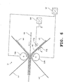
- FIG. 6 shows essential parts of the transfer station T.
- a negative toner system i.e. where the charges the toner particles after being applied to the transfer belts 41, 42 are negatively charged.
- the polarity reversal is in turn caused by the transfer corotron 47a, which in this case, however, has positive potential.
- the transfer rollers 49a, 49b are driven with a voltage U, so that an electric field arises, its field strength compared to the exemplary embodiment according to FIG. 3 reverses.
- the function of the transfer printing corresponds to that described so far, only with the opposite sign of the charge and the field strength.
- Figure 7 shows the possible potential relationships on the Transfer rollers 49a, 49b.
- Figures 7a and 7b one of the transfer rollers 49a, 49b to ground.
- an electrode of the DC voltage source 40 is grounded.
- Figure 7c shows a symmetrical voltage control, wherein the center of tension is grounded.
- Figure 7d shows an asymmetrical voltage control for the transfer rollers 49a and 49b.
- FIG. 8 shows a development of the arrangement according to FIG. 3.
- the substrate 43 to be printed is transferred from the transfer rollers 49a and 49b guided so that there are the transfer rollers 49a, 49b in each case by a predetermined wrap angle wraps. This way the area in which the respective toner image 44 or 45 on the surfaces of the carrier material 43 rests, enlarged. inhomogeneities of the electric field F on its edge have less effect strong out; the fogging effect is reduced.
- Figure 9 shows an embodiment in which in the feed direction of the carrier material 43 seen in front of the transfer rollers 49a and 49b two guide rollers 49c, 49d are arranged, between which the transmission bands 41 and 42 and that Carrier material 43 are guided.
- the two guide rollers 49c and 49d are at ground potential while on the transfer rollers 49a and 49b the voltage U for generating the electric field is applied.
- the two guide rollers 49c, 49d bring the transfer belts 41 and 42 with the Carrier material 43 in contact or reduce the distance a minimum.
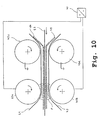
- FIG. 10 shows a detailed representation of the transfer printing area Figure 9.
- the electric field F is between the two transfer rollers 49a and 49b effective. Because of the touch of the toner particles on the transfer belts 41, 42 with the The surface of the carrier material takes place in an electrical field 41 a precise transfer printing.
- Figure 11 shows a variant of the embodiment Figure 9.
- the lower transfer roller 49b and the upper guide roller 49c are subjected to a voltage potential, so that the electric field F between the rollers 49b and 49c is effective.
- the transfer roller 49a and the Guide roller 49d are insulated and have a floating Potential. Due to the measures mentioned, it is possible to reprint required electric field F on a longer one Distance effective, so that the transfer printing process runs more gently, because the effective area on which the transfer of the Toner particles from the transfer belts 41, 42 to the Surface of the carrier material 43 takes place, is enlarged.
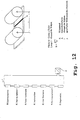
- Figure 13 shows a combination of the embodiments Figures 9 and 11.
- the feed rollers 49e and 49f carry ground potential, while the arrangement of the rollers 49a, 49b, 49c, 49d and the Potential management corresponds to that of Figure 11.
- the arrangement of the rollers 49a, 49b, 49c, 49d and the Potential management corresponds to that of Figure 11.
- the attraction of Neglect toner particles with different potential is. Early skipping of toner particles in the Area of increased distance between the transfer belts 41, 42 is avoided.
- Figure 14 shows a variant of the arrangement of Figure 9.
- the grounded guide rollers 49c, 49d are grounded Deflection bracket 49g, 49h used.
- This deflection bracket 49g, 49h can be placed near the transfer roller 49a, 49b whereby the length of contact of the transfer tapes 41, 42 shortened with the carrier material 43. If you compare them Arrangement according to FIG. 9 with that according to FIG. 14 is too recognize that in Figure 9 the minimum path in which contact between the transfer belts 41, 42 with the carrier material 43 is the sum of the radii of the transfer rollers 49a and 49b and the guide rollers 49c and 49d.
- the deflection bracket 49g, 49h with a friction-reducing Layer, e.g. with a Layer of a fluorine-containing plastic material, e.g. PFA, ETFE, FEP, PVDC, Teflon or polyimide (PI).
- a friction-reducing Layer e.g. with a Layer of a fluorine-containing plastic material, e.g. PFA, ETFE, FEP, PVDC, Teflon or polyimide (PI).
- the surface wear the deflection bracket 49g, 49h can thereby be reduced that hard, wear-resistant materials, e.g. Chrome-nickel steel, VA steel are used, or that the Deflection bracket 49g, 49h with a layer of wear-reducing Material, e.g. by nickel plating, by using silicate or by means of surface hardening.
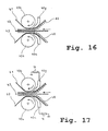
- FIG. 15 shows the current conditions in the example according to FIG. 14, the deflection brackets 49g, 49h being at ground potential.
- the total current Iges results from the sum of the currents Ium at the transfer pressure point and the cross currents Iq1 and Iq2.
- the deflection brackets 49h, 49g can also be arranged in an electrically insulated manner so that they assume floating potential (cf. Figure 16).
- Figure 17 shows an embodiment in which the deflection bracket 49g, 49h are electrically conductive, but via a resistor R are led to ground potential. This too Embodiment according to Figure 17, the cross currents are reduced.
- FIG 18 shows a variant of the embodiment Figure 13.
- the feed rollers 49e, 49f are through deflection brackets 49i, 49j replaced.
- These deflection brackets 49i, 49j can be electrical be designed as in the examples according to the Figures 16 and 17 is indicated.
- Figure 19 shows various embodiments for the transfer rollers.
- the transfer roller is cylindrical and made of an electrically conductive metal as a solid component.
- the transfer roller is made of metal from a tube, ie hollow inside.
- the lower part of the figure in FIG. 19 shows a metallic core, which can consist of solid material or of a tube. This core is covered with a jacket made of high-resistance material.
- the use of a metallic core for the transfer roller is expedient since it has to be manufactured very precisely with little out-of-roundness. In order to minimize runout errors, the circumference of the transfer roller and the length of the transfer belt should be in an integer relationship.
- the transfer belts have a certain fluctuation in thickness, which interferes with the transfer printing process, for example local detachment of the transfer belts from the roller can occur. Therefore, an elastic coating is advantageously applied to the transfer roller, which can compensate for small mechanical tolerances of the components by elastic deformation.
- This coating should have an electrical conductivity in order to be able to build up a strong electrical field in the transfer printing zone on its outer skin.
- the electrical conductivity of the coating should be in the range from 0.5 x 10 -6 to 5 x 10 12 ⁇ cm, but preferably in the range from 0.5 x 10 5 to 5 x 10 9 ⁇ cm.
- the elastic coating should have a Shore hardness in the range from 10 to 90 Sh (A), preferably in the range from 20 to 70 Sh (A).
- the thickness of the elastic coating is 0.2 to 15 mm, preferably 0.5 to 2 mm.
- the elastic coating can additionally have a layer of fluorine-containing plastic material, preferably of PFA, ETFE, FEP, PVDC or Teflon, or of a polyimide layer.
- the additional layer can also be electrically insulating and have a maximum thickness of 40 ⁇ m, preferably from 0.1 to 20 ⁇ m.
- Conductive fillers preferably carbon black, silicates, oxides, can be added to the elastic layer, which enables an increased layer thickness.
- Figure 20 shows a transfer roller that has no continuous has metallic core, but lateral metallic contact cylinder 50.
- the central part 52 of the cylindrical The roller consists of a high-resistance material.
- the resistance R is plotted over the length 1 of the roller. It can be seen that the resistance R increases with increasing length 1 increases, whereby the local current i over the length 1 at applied voltage U drops. It thus result along the length 1 different potentials, which is undesirable.
- Figure 21 shows an embodiment of a transfer roller with a low-resistance, metallic core 56 on which one Coating 54 is applied, which is a relative high-resistance material.
- the core can also be electrical conductive plastic, e.g. from the Material PA that contains soot particles.
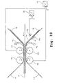
- FIG 22 In Figure 22 is a Umladekorotron Anlagen 110 with two Corotron wires 112 and with two blades Counter electrodes 114 shown.
- As an intermediate carrier is a Photoconductor tape 116 is provided. But it can also be a transfer belt be used.
- the photoconductor belt 116 with a toner image that has not yet been fixed 118, the positively charged toner particle 120 or after of the charge contains negatively charged toner particles 122 between the two corotron wires 112 and the two counter electrodes 114 performed, it being guided by deflection rollers 124 and is driven.
- the blades 114 are on one Bracket 126 attached, which is also the electrical connection to the ground potential of the printing and / or copying device 128 manufactures.
- the corotron wires 112 are on the photoconductor tape 116 opposite side surrounded by two screens 130.
- the photoconductor tape 116 is spaced in the range of 0.2 mm to 4 mm, preferably in the range from 0.2 mm to 1 mm, passed the counter electrodes 114.
- the negatively charged Toner particles 122 of the latent toner image 118 become by the electric field between the corotron wires 112 and recharged the counter electrodes 114.
- FIG. 23 shows a recharging corotron device 110 with a corotron wire 112 and a single blade used as counterelectrode 114, the field lines 132, 134 of the effective electric field being indicated.
- the counter electrode 114 has ground potential. Alternatively, the counter electrode can have a negative potential with respect to the ground potential.
- An electric field is formed between the corotron wire 112 and the counter electrode 114. This field 134 acts on the toner particles 122 which have a negative potential. The toner particles 122 are discharged as they pass the corotron wire 112 and charged to a positive potential.
- the magnitude of the potential of the now positively charged toner 120 depends on the duration of the toner in the electric field and on the density of the electric field.
- the photoconductor tape 116 is attracted by the counter electrode 114.
- ⁇ r is the dielectric constant of the air between photoconductor band 116 and counter electrode 114
- A is the surface 136 of the counter electrode 114 effective in the electric field
- U is the potential difference
- d is the distance between the underside of the photoconductor band 116 and the counter electrode 114.
- FIG. Another counter electrode 114 is shown in FIG. which is designed as a blade.
- This blade 114 has one rectangular cross section and is by a holder 126 in Printer and / or copier 128 attached.
- a blade 114 is shown, the cutting edge is jagged.
- the blade 114 is in the printer / copier 128 arranged so that the teeth 140 in the direction of the photoconductor belt 116 taper.
- the tines 140 are equidistant arranged. This arrangement ensures even transhipment of the latent toner image 118 guaranteed.
- the keeper 126 of the blade 114 is not shown in this figure 25.
- FIG. 26 shows a counter electrode 114 which consists of an arrangement of single pins 142.
- Pins 142 are arranged on a holder 126 at symmetrical intervals.
- the holder 126 is so in the printer and / or copier 128 arranged that the ends of the individual pins 142 in a parallel Level to the photoconductor tape 116 or to the corotron wire 112, and lie parallel to the corotron wire.
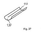
- FIG. 27 shows a counter electrode 114 which consists of there is a wire 144.
- the wire 144 is replaced by a suitable one Holding device 126 in the printer and / or copier 128 so arranged that it is in a plane parallel to the photoconductor belt 116 and parallel to the corotron wire 112.
- a screen 130 is arranged on the is the side of the wire 144 facing away from the photoconductor band 116 .
- the wire 144 is a corotron wire 112 similar wire 144 inserted.
- FIG. 28 shows a transfer printing corotron device 146 with a Corotron wire 112 and with a blade 114 Counter electrode shown.
- One more unfixed toner image 118a on the photoconductor belt 116a contains positively charged toner particles 120.
- Not yet contains fixed toner image 118b on the photoconductor belt 116b negatively charged toner particles 122.
- the photoconductor tapes 116a and 116b and a paper web 148 are between the corotron wire 112 and the blade 114 without touching them performed, the photoconductor belts 116a, 116b by deflection rollers 124 are guided and driven. The drive and the guidance of the paper web 148 is not in this figure shown.
- Corotone wire 112 has a positive potential and blade 114 has a negative potential to the ground potential.
- the corotron wire 112 is on the Photoconductor tape 116a facing away from a screen 130 surround.
- the positively charged latent toner particles 120 Toner image 118a are from the positively charged corotron wire 112 repelled and from the negatively charged toner particles 122 of the latent toner image 118b and of the negatively charged one Blade 114 tightened. Similarly, they become negative charged toner particle 122 of the latent toner image 118b of the negatively charged blade 114 and repelled by the positively charged toner particles 120 of the latent toner image 118a and attracted by the positively charged corotron wire 112.
- On the positively and negatively charged toner particles 120, 122 acts through the transfer corotron 146 a force that is greater than the binding forces between the toner particles 120, 122 and the photoconductor tapes 116a, 116b.
- the positive and negatively charged toner particles 120, 122 are replaced by the Field forces of the electric field are printed on the paper web 146.
- the toner particles remain on the paper web 146 120, 122 by the binding forces between the toner particles 120, 122 and the paper web 146 as well as by the attraction between the positively charged toner particles 120 one side of the paper and the negatively charged toner particles 122 stick on the other side of the paper.
Abstract
Description
- Figur 1
- eine schematische Schnittdarstellung eines elektrofotografischen Druckgeräts zum monochromen und/oder farbigen, ein- oder beidseitigen Bedrucken eines bandförmigen Trägermaterials, bei dem die Transferstation nach der Erfindung eingesetzt werden kann,
- Figur 2
- eine schematische Schnittdarstellung eines Druckgeräts nach Figur 1, welches das Trägermaterial beidseitig bedruckt,
- Figur 3
- schematisch eine Anordnung wesentlicher Teile der Transferstation mit Umladung der Tonerteilchen,
- Figur 4
- eine Detaildarstellung der Anordnung nach Figur 3 zur Erläuterung der Wirkungsweise,
- Figur 5
- ein elektrisches Ersatzschaltbild, das die Widerstandsverhältnisse und Stromverhältnisse an der Umdruckstelle wiedergibt,
- Figur 6
- eine Anordnung ähnlich der nach Figur 3 mit negativem Tonersystem,
- Figur 7
- schematisch die möglichen Potentialverhältnisse an den Umdruckwalzen,
- Figur 8
- ein Ausführungsbeispiel, bei dem die Übertragungsbänder die Übertragungswalzen teilweise umschlingen,
- Figur 9
- ein Ausführungsbeispiel mit Führungswalzen,
- Figur 10
- eine Detaildarstellung der Anordnung nach Figur 9,
- Figur 11
- eine Anordnung ähnlich der nach Figur 9, bei der das zum Umdrucken erforderliche elektrische Feld zwischen der Führungswalze und der Übertragungswalze aufgebaut wird,
- Figur 12
- ein elektrisches Ersatzschaltbild zum Ausführungsbeispiel nach Figur 11,
- Figur 13
- eine Anordnung nach Figur 11, wobei zusätzlich Zuführwalzen vorgesehen sind,
- Figur 14
- ein Ausführungsbeispiel mit Umlenkbügeln,
- Figur 15
- die Stromverhältnisse beim Ausführungsbeispiel nach Figur 14,
- Figur 16
- das Ausführungsbeispiel nach Figur 14 mit isolierten Umlenkbügeln,
- Figur 17
- ein Ausführungsbeispiel mit elektrisch leitenden Umlenkbügeln, die über einen Widerstand gegen Massepotential geführt sind,
- Figur 18
- ein Ausführungsbeispiel ähnlich dem nach Figur 13,
- Figur 19
- mehrere Ausführungsbeispiele für eine Übertragungswalze,
- Figur 20
- eine Übertragungswalze aus einem hochohmigen Material mit seitlichen Elektrodenanschlüssen,
- Figur 21
- eine Übertragungswalze mit einem elektrisch leitenden Kern und einer hochohmigen Beschichtung,
- Figur 22
- eine Umladekorotroneinrichtung mit zwei Korotrondrähten und mit zwei als Klingen ausgebildeten Gegenelektroden,
- Figur 23
- ein Umladekorotron mit einem Korotrondraht und einer als Gegenelektrode eingesetzten Klinge, wobei die Feldlinien des wirksamen elektrischen Feldes angedeutet sind,
- Figur 24
- die Darstellung einer Gegenelektrode, die als Klinge ausgeführt ist,
- Figur 25
- die Darstellung einer Klinge, wobei die Schneide gezackt ist,
- Figur 26
- die Darstellung einer Gegenelektrode, die aus einer Anordnung von Einzelstiften besteht,
- Figur 27
- die Darstellung einer Gegenelektrode, die aus einem Draht besteht, und
- Figur 28
- eine Umdruckkorotroneinrichtung mit einem Korotrondraht und mit einer als Klinge ausgebildeten Gegenelektrode.
- M1
- Zuführungsmodul
- M2
- Druckmodul
- M3
- Fixiermodul
- M4
- Nachverarbeitungsmodul
- 10
- Aufzeichnungsträger, Papier, Einzelblatt bzw. Endlospapier
- 11
- Transportkanal
- E1
- Elektrophotographiemodul, Frontseite
- E2
- Elektrophotographiemodul, Rückseite
- T1
- Transfermodul, Frontseite
- T2
- Transfermodul, Rückseite
- 12
- Umlenkwalzen
- 13
- Photoleiter
- 14
- Ladeeinrichtung
- 15
- Zeichengenerator
- 16/1 bis 16/5
- Entwicklerstationen
- 17
- Zwischenbelichtungseinrichtung
- 18
- Umdruckeinrichtung, Transferbereich
- 19
- Transferband
- 20
- Übertragungskoronaeinrichtung
- 21
- Endladekoronaeinrichtung
- 22
- Reinigungsstation
- 23
- Zwischenbelichtungseinrichtung
- 24
- Umdruckstation
- 25
- Umlenkwalze
- 26
- Reinigungsstation
- 27
- Umlenkwalze
- 28
- Umdruckwalze
- 29
- Umdruckkorotron
- 30
- Schlaufenzieher
- 31
- Stapeleinrichtung
- 32
- Infrarotstrahler
- 33
- Umlenkwalze
- 34
- Kühlelement
- 35
- Umlenkwalze
- 36
- Schneideeinrichtung
- 37
- Stapeleinrichtung
- GS
- Gerätesteuerung
- ST
- Steuereinrichtung
- B
- Bedienteil
- 38
- Transportwalzen
- 39
- Lade-Koronaeinrichtung
- B1
- Bilderzeugende Einrichtung
- B2
- Bilderzeugende Einrichtung
- 40
- Gleichspannungsquelle
- 41
- oberes Übertragungsband
- 42
- unteres Übertragungsband
- 43
- Trägermaterial
- 44
- Tonerbild
- 45
- Tonerbild
- 46
- umgeladene Tonerteilchen
- 47a
- Umladekorotron
- 47b
- Masseelektrode
- 48
- Gleichspannungsquelle
- 49a, 49b
- Übertragungswalzen
- 49c, 49d
- Führungswalzen
- 49e, 49f
- Zuführwalzen
- 49g, 49h
- Umlenkbügel
- 49i, 49j
- Umlenkbügel gegen Masse geführt
- P1
- Transportpfeil
- T
- Transferstation
- 50
- Kontaktierung
- 52
- Mittelteil
- 54
- Beschichtung
- 56
- Kern
- F
- elektrisches Feld
- F1
- Feldlinie
- R
- Widerstand
- U
- Spannung
- i
- Strom
- 1
- Länge
- A
- effektive Fläche
- ρ
- spezifischer Widerstand
- 110
- Umladekorotroneinrichtung
- 112
- Korotrondraht
- 114
- Gegenelektrode
- 116
- Fotoleiterband
- 118
- latentes Tonerbild
- 120
- positiv geladene Tonerpartikel
- 122
- negativ geladene Tonerpartikel
- 124
- Umlenkwalze
- 126
- Halter
- 128
- Druck- und/oder Kopiereinrichtung
- 130
- Schirm
- 132
- Feldlinien
- 134
- Feldlinien
- 136
- im elektrischen Feld wirksame Fläche der Gegenelektrode
- 140
- Zacken
- 142
- Einzelstifte
- 144
- Draht
- 146
- Umdruckkorotron
- 148
- Papierbahn
Claims (16)
- Druck- oder Kopiereinrichtung mit einer Korotroneinrichtung (110),
mit mindestens einem Korotrondraht (112) mit einem ersten Potential,
mit mindestens einer Gegenelektrode (114) mit einem vom ersten Potential verschiedenen zweiten Potential,
und mit mindestens einem zwischen Korotrondraht (112) und Gegenelektrode (114) geführten Zwischenträger (116) für Tonerbilder,
dadurch gekennzeichnet, daß
die Gegenelektrode (114) elektrisch leitende Erhebungen (140, 142) hat, deren Endpunkte in Richtung des Korotrondrahtes (112) ragen und die in einer Ebene parallel zur Längsachse des Korotrondrahtes (112) und parallel zum Zwischenträger (116) liegen. - Einrichtung nach Anspruch 1, dadurch gekennzeichnet, daß diese Erhebungen (140, 142) parallel zur Längsachse des Korotrondrahtes (112) verlaufen.
- Einrichtung nach einem der vorhergehenden Ansprüche, dadurch gekennzeichnet, daß die Gegenelektrode (114) als Erhebungen Einzelstifte (142) enthält.
- Einrichtung nach einem der vorhergehenden Ansprüche, dadurch gekennzeichnet, daß die Gegenelektrode (114) spitz zulaufende Erhebungen (140, 142) enthält.
- Druck- oder Kopiereinrichtung mit einer Korotroneinrichtung (110),
mit mindestens einem Korotrondraht (112) mit einem ersten Potential,
mit mindestens einer Gegenelektrode (114) mit einem vom ersten Potential verschiedenen zweiten Potential,
und mit mindestens einem zwischen Korotrondraht (112) und Gegenelektrode (114) geführten Zwischenträger (116) für Tonerbilder,
dadurch gekennzeichnet, daß
die Gegenelektrode (114) nach Art einer Klinge mit einer Schneide ausgebildet ist, wobei die Schneide parallel zur Längsachse des Korotrondrahtes (112) angeordnet ist. - Einrichtung nach Anspruch 5, dadurch gekennzeichnet, daß die Schneide gezackt ist, und daß die Endpunkte und/oder Endflächen der Zacken (140) in Richtung des Korotrondrahtes (112) ragen und parallel zur Längsachse des Korotrondrahtes (112) liegen.
- Einrichtung nach Anspruch 6, dadurch gekennzeichnet, daß die Zacken (140) in Richtung des Korotrondrahtes (112) spitz zulaufen.
- Einrichtung nach einem der vorhergehenden Ansprüche 5 bis 7, dadurch gekennzeichnet, daß der Querschnitt der Klinge (114) sich in Richtung des Korotrondrahtes (112) verjüngt.
- Einrichtung nach einem der vorhergehenden Ansprüche 5 bis 8, dadurch gekennzeichnet, daß die Schneide eine Breite hat, die im Bereich von 0,02 mm bis 0,5 mm, vorzugsweise im Bereich von 0,02 mm bis 0,1 mm liegt.
- Druck- oder Kopiereinrichtung mit einer Korotroneinrichtung (110),
mit mindestens einem Korotrondraht (112) mit einem ersten Potential,
mit mindestens einer Gegenelektrode (114) mit einem vom ersten Potential verschiedenen zweiten Potential,
und mit mindestens einem zwischen Korotrondraht (112) und Gegenelektrode (114) geführten Zwischenträger (116) für Tonerbilder,
dadurch gekennzeichnet, daß
die Gegenelektrode (114) als Draht (144) ausgebildet ist, wobei die Längsachse des Drahtes (144) parallel zur Längsachse des Korotrondrahtes (112) angeordnet ist. - Einrichtung nach einem der vorhergehenden Ansprüche 1 bis 10, dadurch gekennzeichnet, daß der Korotrondraht (112) und die Gegenelektrode (114) in einer Ebene liegen, die senkrecht zum Zwischenträger (116) steht.
- Einrichtung nach einem der vorhergehenden Ansprüche, dadurch gekennzeichnet, daß der Zwischenträger (116) ein Fotoleiterband oder ein Transferband ist.
- Einrichtung nach einem der vorhergehenden Ansprüche, dadurch gekennzeichnet, daß die Korotroneinrichtung (110) ein Umladekorotron, ein Ladekorotron, ein Umdruckkorotron oder ein Löschkorotron ist.
- Einrichtung nach einem der vorhergehenden Ansprüche, dadurch gekennzeichnet, daß der Zwischenträger (116) in einem Abstand in einem Bereich von 0,2 mm bis 4 mm, vorzugsweise in einem Bereich von 0,2 mm bis 1 mm, an der Gegenelektrode (114) vorbeigeführt wird.
- Einrichtung nach einem der vorhergehenden Ansprüche, dadurch gekennzeichnet, daß die Gegenelektrode (114) Massepotential besitzt.
- Einrichtung nach einem der vorhergehenden Ansprüche, dadurch gekennzeichnet, daß der Zwischenträger (116) aus einem hochohmigen Material besteht, das einen spezifischen Widerstand von >106 Ohm cm besitzt.
Applications Claiming Priority (3)
| Application Number | Priority Date | Filing Date | Title |
|---|---|---|---|
| DE19840201 | 1998-09-03 | ||
| DE19840201 | 1998-09-03 | ||
| EP99947276A EP1110125B1 (de) | 1998-09-03 | 1999-09-03 | Drucker oder kopierer zum simultanen beidseitigen bedrucken eines trägermaterials |
Related Parent Applications (2)
| Application Number | Title | Priority Date | Filing Date |
|---|---|---|---|
| EP99947276.4 Division | 1999-09-03 | ||
| EP99947276A Division-Into EP1110125B1 (de) | 1998-09-03 | 1999-09-03 | Drucker oder kopierer zum simultanen beidseitigen bedrucken eines trägermaterials |
Publications (2)
| Publication Number | Publication Date |
|---|---|
| EP1465023A1 true EP1465023A1 (de) | 2004-10-06 |
| EP1465023B1 EP1465023B1 (de) | 2010-11-10 |
Family
ID=7879705
Family Applications (2)
| Application Number | Title | Priority Date | Filing Date |
|---|---|---|---|
| EP04012249A Expired - Lifetime EP1465023B1 (de) | 1998-09-03 | 1999-09-03 | Korotron mit Gegenelektrode |
| EP99947276A Expired - Lifetime EP1110125B1 (de) | 1998-09-03 | 1999-09-03 | Drucker oder kopierer zum simultanen beidseitigen bedrucken eines trägermaterials |
Family Applications After (1)
| Application Number | Title | Priority Date | Filing Date |
|---|---|---|---|
| EP99947276A Expired - Lifetime EP1110125B1 (de) | 1998-09-03 | 1999-09-03 | Drucker oder kopierer zum simultanen beidseitigen bedrucken eines trägermaterials |
Country Status (4)
| Country | Link |
|---|---|
| US (1) | US6556804B1 (de) |
| EP (2) | EP1465023B1 (de) |
| DE (2) | DE59911378D1 (de) |
| WO (1) | WO2000014607A2 (de) |
Cited By (2)
| Publication number | Priority date | Publication date | Assignee | Title |
|---|---|---|---|---|
| DE102004057999A1 (de) * | 2004-12-01 | 2006-06-08 | OCé PRINTING SYSTEMS GMBH | Vorrichtung und Verfahren zum Umdrucken eines Tonerbildes aus elektrisch geladenen Tonerteilchen von einem Tonerbildträger auf ein Trägermaterial |
| DE102005023462A1 (de) * | 2005-05-20 | 2006-11-23 | OCé PRINTING SYSTEMS GMBH | Vorrichtung und Verfahren zum beidseitigen Bedrucken eines Aufzeichnungsträgers mit Umlade- und Nachladevorrichtung |
Families Citing this family (20)
| Publication number | Priority date | Publication date | Assignee | Title |
|---|---|---|---|---|
| FI118542B (fi) * | 2002-03-14 | 2007-12-14 | Metso Paper Inc | Pintakäsittelyprosessi |
| FI121123B (fi) * | 2002-03-14 | 2010-07-15 | Metso Paper Inc | Menetelmä jatkuvan rainan pinnan päällystämiseksi kuivapäällystysjauheella |
| US6671486B1 (en) * | 2002-06-06 | 2003-12-30 | Xerox Corporation | Common polarity toner duplexing electrostatographic reproduction machine |
| US7039349B2 (en) * | 2002-10-31 | 2006-05-02 | Ricoh Company, Ltd. | Image forming apparatus transferring toner images to both surfaces of a recording medium |
| US7054587B2 (en) * | 2003-06-23 | 2006-05-30 | Ricoh Company, Ltd. | Image forming apparatus for recording on two sides in a single pass |
| KR100532114B1 (ko) * | 2004-01-19 | 2005-11-29 | 삼성전자주식회사 | 현상장치 및 이를 이용한 전자사진방식 화상형성장치 |
| DE102004003543A1 (de) | 2004-01-23 | 2005-10-27 | OCé PRINTING SYSTEMS GMBH | Endloser Zwischenbildträger für einen elektrofotografischen Drucker oder Kopierer |
| DE102004005965A1 (de) * | 2004-02-06 | 2005-09-08 | OCé PRINTING SYSTEMS GMBH | Vorrichtung zum Antrieb eines Bandes bei einer elektrografischen Druck- oder Kopiereinrichtung |
| US7295799B2 (en) * | 2004-03-29 | 2007-11-13 | Eastman Kodak Company | Synchronous duplex printing systems using pulsed DC fields |
| US7391425B2 (en) * | 2004-03-29 | 2008-06-24 | Eastman Kodak Company | Synchronous duplex printing systems using directed charged particle of aerosol toner development |
| JP2006267779A (ja) * | 2005-03-25 | 2006-10-05 | Pfu Ltd | 液体現像電子写真装置 |
| NL1029189C2 (nl) * | 2005-06-06 | 2006-12-14 | Oce Tech Bv | Printprocédé in combinatie met een toner geschikt voor toepassing in dit procédé. |
| JP2006341958A (ja) * | 2005-06-09 | 2006-12-21 | Konica Minolta Business Technologies Inc | 用紙搬送装置 |
| US20070135979A1 (en) * | 2005-12-09 | 2007-06-14 | Smartdrive Systems Inc | Vehicle event recorder systems |
| JP2008026494A (ja) * | 2006-07-19 | 2008-02-07 | Toshiba Corp | 画像形成装置及び画像形成方法 |
| DE102008016163A1 (de) | 2008-03-28 | 2009-10-08 | OCé PRINTING SYSTEMS GMBH | Vorrichtung zum simultanen beidseitigen Bedrucken eines Bedruckstoffs durch ein elektrofotografisches Druck- oder Kopiergerät |
| JP2010008968A (ja) * | 2008-06-30 | 2010-01-14 | Ricoh Co Ltd | 転写装置およびそれを備えた画像形成装置 |
| DE102010016856A1 (de) | 2010-05-10 | 2011-11-10 | OCé PRINTING SYSTEMS GMBH | Druckeinrichtung zum beidseitigen Bedrucken eines bandförmigen Bedruckstoffs |
| DE102013107451A1 (de) | 2013-07-15 | 2015-01-15 | Océ Printing Systems GmbH & Co. KG | Druckeinrichtung zum beidseitigen Bedrucken eines bandförmigen Bedruckstoffs |
| US9429883B1 (en) * | 2015-11-10 | 2016-08-30 | Kabushiki Kaisha Toshiba | Image forming apparatus and image forming method |
Citations (6)
| Publication number | Priority date | Publication date | Assignee | Title |
|---|---|---|---|---|
| DE3146826A1 (de) * | 1981-11-26 | 1983-06-01 | Klaus 4803 Steinhagen Kalwar | Vorrichtung zur oberflaechenbehandlung von folienartigen werkstoffen mit koronaentladungen |
| WO1987002792A1 (en) | 1985-11-04 | 1987-05-07 | Eastman Kodak Company | Electrographic reproduction apparatus |
| EP0320985A2 (de) | 1987-12-18 | 1989-06-21 | Colorocs Corporation | Senkrechte Druckeinrichtung für elektrofotographisches Gerät |
| US5477315A (en) * | 1994-07-05 | 1995-12-19 | Xerox Corporation | Electrostatic coupling force arrangement for applying vibratory motion to a flexible planar member |
| US5521383A (en) * | 1993-06-18 | 1996-05-28 | Sharp Kabushiki Kaisha | Corona discharge device |
| DE19713964A1 (de) | 1996-04-04 | 1997-11-20 | Fuji Xerox Co Ltd | Vorrichtung zur Erzeugung beidseitiger Bilder und Verfahren zur Verwendung derselben |
Family Cites Families (5)
| Publication number | Priority date | Publication date | Assignee | Title |
|---|---|---|---|---|
| JPH06102778A (ja) * | 1992-09-18 | 1994-04-15 | Ricoh Co Ltd | 画像形成方法 |
| EP0775948A1 (de) * | 1995-11-24 | 1997-05-28 | Xeikon Nv | Mehrfarben elektrostatographischer Drucker mit einem Umlauf |
| KR970028908A (ko) * | 1995-11-24 | 1997-06-24 | 엘 드 샴펠라에레 | 싱글 패스 다색 정전 사진 프린터 |
| CN1115608C (zh) * | 1997-03-03 | 2003-07-23 | Oce印刷系统有限公司 | 能调节性能地进行印刷的印刷或复印装置及方法 |
| JPH11212308A (ja) * | 1998-01-27 | 1999-08-06 | Fuji Xerox Co Ltd | 両面画像形成装置 |
-
1999
- 1999-09-03 EP EP04012249A patent/EP1465023B1/de not_active Expired - Lifetime
- 1999-09-03 WO PCT/EP1999/006487 patent/WO2000014607A2/de active IP Right Grant
- 1999-09-03 DE DE59911378T patent/DE59911378D1/de not_active Expired - Lifetime
- 1999-09-03 DE DE59915218T patent/DE59915218D1/de not_active Expired - Lifetime
- 1999-09-03 US US09/786,257 patent/US6556804B1/en not_active Expired - Fee Related
- 1999-09-03 EP EP99947276A patent/EP1110125B1/de not_active Expired - Lifetime
Patent Citations (7)
| Publication number | Priority date | Publication date | Assignee | Title |
|---|---|---|---|---|
| DE3146826A1 (de) * | 1981-11-26 | 1983-06-01 | Klaus 4803 Steinhagen Kalwar | Vorrichtung zur oberflaechenbehandlung von folienartigen werkstoffen mit koronaentladungen |
| WO1987002792A1 (en) | 1985-11-04 | 1987-05-07 | Eastman Kodak Company | Electrographic reproduction apparatus |
| EP0320985A2 (de) | 1987-12-18 | 1989-06-21 | Colorocs Corporation | Senkrechte Druckeinrichtung für elektrofotographisches Gerät |
| US5521383A (en) * | 1993-06-18 | 1996-05-28 | Sharp Kabushiki Kaisha | Corona discharge device |
| US5477315A (en) * | 1994-07-05 | 1995-12-19 | Xerox Corporation | Electrostatic coupling force arrangement for applying vibratory motion to a flexible planar member |
| DE19713964A1 (de) | 1996-04-04 | 1997-11-20 | Fuji Xerox Co Ltd | Vorrichtung zur Erzeugung beidseitiger Bilder und Verfahren zur Verwendung derselben |
| US5797077A (en) | 1996-04-04 | 1998-08-18 | Fuji Xerox Co., Ltd. | Double-sided images forming apparatus and method using the same |
Cited By (3)
| Publication number | Priority date | Publication date | Assignee | Title |
|---|---|---|---|---|
| DE102004057999A1 (de) * | 2004-12-01 | 2006-06-08 | OCé PRINTING SYSTEMS GMBH | Vorrichtung und Verfahren zum Umdrucken eines Tonerbildes aus elektrisch geladenen Tonerteilchen von einem Tonerbildträger auf ein Trägermaterial |
| DE102004057999B4 (de) * | 2004-12-01 | 2007-02-15 | OCé PRINTING SYSTEMS GMBH | Vorrichtung und Verfahren zum Umdrucken eines Tonerbildes aus elektrisch geladenen Tonerteilchen von einem Tonerbildträger auf ein Trägermaterial |
| DE102005023462A1 (de) * | 2005-05-20 | 2006-11-23 | OCé PRINTING SYSTEMS GMBH | Vorrichtung und Verfahren zum beidseitigen Bedrucken eines Aufzeichnungsträgers mit Umlade- und Nachladevorrichtung |
Also Published As
| Publication number | Publication date |
|---|---|
| WO2000014607A3 (de) | 2000-08-24 |
| EP1110125B1 (de) | 2004-12-29 |
| EP1110125A2 (de) | 2001-06-27 |
| DE59911378D1 (de) | 2005-02-03 |
| DE59915218D1 (de) | 2010-12-23 |
| WO2000014607A2 (de) | 2000-03-16 |
| EP1465023B1 (de) | 2010-11-10 |
| US6556804B1 (en) | 2003-04-29 |
Similar Documents
| Publication | Publication Date | Title |
|---|---|---|
| EP1110125B1 (de) | Drucker oder kopierer zum simultanen beidseitigen bedrucken eines trägermaterials | |
| DE4420667C2 (de) | Spannungsreinigungssystem, elektrostatische Druckvorrichtung und Verfahren zum Betrieb des Systems und der Vorrichtung | |
| EP0965070B1 (de) | Druck- und kopiergerät zum performance-angepassten, monochromen und/oder farbigen, ein- oder beidseitigen bedrucken eines aufzeichnungsträgers | |
| DE69927324T2 (de) | Bilderzeugungsgerät | |
| DE19618905C2 (de) | Elektrostatische Bilderzeugungseinrichtung | |
| DE19501544C2 (de) | Bilderzeugungseinrichtung | |
| DE19523767A1 (de) | Vorrichtung zum Übertragen eines Bildes und Verfahren zum Reinigen eines Übertragungsbandes | |
| DE2842516B2 (de) | Entwicklungseinrichtung für ein elektrophotographisches Kopiergerät | |
| DE19617152A1 (de) | Entwicklungseinrichtung für ein elektrophotographisches Aufzeichnungsgerät | |
| DE4324148C2 (de) | Riemen-Übertragungseinrichtung für elektrophotographisches Gerät | |
| EP0570419A1 (de) | Kopiergerät mit einem bandförmigen transferelement. | |
| DE19611967A1 (de) | Bilderzeugungseinrichtung und Verfahren zum Reinigen einer Übertragungsvorrichtung einer Bilderzeugungseinrichtung | |
| DE3833302A1 (de) | Papiertransport fuer die elektrofotografische bilderzeugung | |
| DE2058481A1 (de) | Verfahren und Vorrichtung zur UEbertragung eines elektrophotographischen Tonerbildes | |
| DE2359532A1 (de) | Vorrichtung zum elektrischen laden einer flaeche, deren ladungsempfaenglichkeit von der temperatur abhaengt | |
| DE10351219A1 (de) | Übertragung von Toner mit einem zeitvariablen Übertragungsstationsstrom | |
| DE60219787T2 (de) | ENTWICKLUNGSEINRICHTUNG mit elektrischem Feld in Form von Wanderwellen | |
| DE19813205A1 (de) | Reinigungsvorrichtung für eine Bildübertragungsband-Vorrichtung | |
| DE69735690T2 (de) | Gerät zur Bilderzeugung unter Verwendung eines Zwischenübertragungselementes | |
| WO2006122847A1 (de) | Vorrichtung und verfahren zum beidseitigen bedrucken eines aufzeichnungsträgers mit umlade- und nachladevorrichtung | |
| DE2410741A1 (de) | Regler fuer reproduktionsgeraete | |
| DE19524512A1 (de) | Bilderzeugungsvorrichtung und Verfahren zum Reinigen des Übertragungs-/Fördermittels | |
| DE3436648A1 (de) | Elektrostatische aufzeichnungseinrichtung | |
| EP1527375B1 (de) | Verfahren und vorrichtung zur minimierung von unerwünschtem tonerübertrag in einer umdruckstation eines elektrografischen druckgeräts | |
| DE102009024600B4 (de) | Verfahren und Vorrichtung zum Übertragen einer Menge elektrisch geladener Tonerteilchen zwischen mindestens zwei Tonerträgern |
Legal Events
| Date | Code | Title | Description |
|---|---|---|---|
| PUAI | Public reference made under article 153(3) epc to a published international application that has entered the european phase |
Free format text: ORIGINAL CODE: 0009012 |
|
| AC | Divisional application: reference to earlier application |
Ref document number: 1110125 Country of ref document: EP Kind code of ref document: P |
|
| AK | Designated contracting states |
Kind code of ref document: A1 Designated state(s): BE DE FR GB |
|
| 17P | Request for examination filed |
Effective date: 20040929 |
|
| AKX | Designation fees paid |
Designated state(s): BE DE FR GB |
|
| 17Q | First examination report despatched |
Effective date: 20100121 |
|
| GRAP | Despatch of communication of intention to grant a patent |
Free format text: ORIGINAL CODE: EPIDOSNIGR1 |
|
| GRAS | Grant fee paid |
Free format text: ORIGINAL CODE: EPIDOSNIGR3 |
|
| GRAA | (expected) grant |
Free format text: ORIGINAL CODE: 0009210 |
|
| AC | Divisional application: reference to earlier application |
Ref document number: 1110125 Country of ref document: EP Kind code of ref document: P |
|
| AK | Designated contracting states |
Kind code of ref document: B1 Designated state(s): BE DE FR GB |
|
| REG | Reference to a national code |
Ref country code: GB Ref legal event code: FG4D Free format text: NOT ENGLISH |
|
| REF | Corresponds to: |
Ref document number: 59915218 Country of ref document: DE Date of ref document: 20101223 Kind code of ref document: P |
|
| PLBE | No opposition filed within time limit |
Free format text: ORIGINAL CODE: 0009261 |
|
| STAA | Information on the status of an ep patent application or granted ep patent |
Free format text: STATUS: NO OPPOSITION FILED WITHIN TIME LIMIT |
|
| 26N | No opposition filed |
Effective date: 20110811 |
|
| REG | Reference to a national code |
Ref country code: DE Ref legal event code: R097 Ref document number: 59915218 Country of ref document: DE Effective date: 20110811 |
|
| BERE | Be: lapsed |
Owner name: OCE PRINTING SYSTEMS G.M.B.H. Effective date: 20110930 |
|
| PG25 | Lapsed in a contracting state [announced via postgrant information from national office to epo] |
Ref country code: BE Free format text: LAPSE BECAUSE OF NON-PAYMENT OF DUE FEES Effective date: 20110930 |
|
| PGFP | Annual fee paid to national office [announced via postgrant information from national office to epo] |
Ref country code: GB Payment date: 20120926 Year of fee payment: 14 |
|
| PGFP | Annual fee paid to national office [announced via postgrant information from national office to epo] |
Ref country code: FR Payment date: 20121008 Year of fee payment: 14 Ref country code: DE Payment date: 20121129 Year of fee payment: 14 |
|
| REG | Reference to a national code |
Ref country code: DE Ref legal event code: R082 Ref document number: 59915218 Country of ref document: DE Representative=s name: PATENTANWAELTE SCHAUMBURG, THOENES, THURN, LAN, DE |
|
| REG | Reference to a national code |
Ref country code: DE Ref legal event code: R082 Ref document number: 59915218 Country of ref document: DE Representative=s name: PATENTANWAELTE SCHAUMBURG, THOENES, THURN, LAN, DE Effective date: 20130819 Ref country code: DE Ref legal event code: R081 Ref document number: 59915218 Country of ref document: DE Owner name: OCE PRINTING SYSTEMS GMBH & CO. KG, DE Free format text: FORMER OWNER: OCE PRINTING SYSTEMS GMBH, 85586 POING, DE Effective date: 20130819 |
|
| GBPC | Gb: european patent ceased through non-payment of renewal fee |
Effective date: 20130903 |
|
| REG | Reference to a national code |
Ref country code: FR Ref legal event code: TP Owner name: OCE PRINTING SYSTEMS GMBH & CO. KG, DE Effective date: 20140513 |
|
| REG | Reference to a national code |
Ref country code: FR Ref legal event code: ST Effective date: 20140530 |
|
| REG | Reference to a national code |
Ref country code: DE Ref legal event code: R119 Ref document number: 59915218 Country of ref document: DE Effective date: 20140401 |
|
| PG25 | Lapsed in a contracting state [announced via postgrant information from national office to epo] |
Ref country code: GB Free format text: LAPSE BECAUSE OF NON-PAYMENT OF DUE FEES Effective date: 20130903 |
|
| PG25 | Lapsed in a contracting state [announced via postgrant information from national office to epo] |
Ref country code: FR Free format text: LAPSE BECAUSE OF NON-PAYMENT OF DUE FEES Effective date: 20130930 Ref country code: DE Free format text: LAPSE BECAUSE OF NON-PAYMENT OF DUE FEES Effective date: 20140401 |
|
| REG | Reference to a national code |
Ref country code: GB Ref legal event code: 732E Free format text: REGISTERED BETWEEN 20140904 AND 20140910 |