EP1465023A1 - Corotron with counter electrode - Google Patents
Corotron with counter electrode Download PDFInfo
- Publication number
- EP1465023A1 EP1465023A1 EP04012249A EP04012249A EP1465023A1 EP 1465023 A1 EP1465023 A1 EP 1465023A1 EP 04012249 A EP04012249 A EP 04012249A EP 04012249 A EP04012249 A EP 04012249A EP 1465023 A1 EP1465023 A1 EP 1465023A1
- Authority
- EP
- European Patent Office
- Prior art keywords
- transfer
- corotron
- counter electrode
- wire
- carrier
- Prior art date
- Legal status (The legal status is an assumption and is not a legal conclusion. Google has not performed a legal analysis and makes no representation as to the accuracy of the status listed.)
- Granted
Links
Images


Classifications
-
- G—PHYSICS
- G03—PHOTOGRAPHY; CINEMATOGRAPHY; ANALOGOUS TECHNIQUES USING WAVES OTHER THAN OPTICAL WAVES; ELECTROGRAPHY; HOLOGRAPHY
- G03G—ELECTROGRAPHY; ELECTROPHOTOGRAPHY; MAGNETOGRAPHY
- G03G15/00—Apparatus for electrographic processes using a charge pattern
- G03G15/14—Apparatus for electrographic processes using a charge pattern for transferring a pattern to a second base
- G03G15/16—Apparatus for electrographic processes using a charge pattern for transferring a pattern to a second base of a toner pattern, e.g. a powder pattern, e.g. magnetic transfer
- G03G15/163—Apparatus for electrographic processes using a charge pattern for transferring a pattern to a second base of a toner pattern, e.g. a powder pattern, e.g. magnetic transfer using the force produced by an electrostatic transfer field formed between the second base and the electrographic recording member, e.g. transfer through an air gap
-
- G—PHYSICS
- G03—PHOTOGRAPHY; CINEMATOGRAPHY; ANALOGOUS TECHNIQUES USING WAVES OTHER THAN OPTICAL WAVES; ELECTROGRAPHY; HOLOGRAPHY
- G03G—ELECTROGRAPHY; ELECTROPHOTOGRAPHY; MAGNETOGRAPHY
- G03G15/00—Apparatus for electrographic processes using a charge pattern
- G03G15/22—Apparatus for electrographic processes using a charge pattern involving the combination of more than one step according to groups G03G13/02 - G03G13/20
- G03G15/23—Apparatus for electrographic processes using a charge pattern involving the combination of more than one step according to groups G03G13/02 - G03G13/20 specially adapted for copying both sides of an original or for copying on both sides of a recording or image-receiving material
- G03G15/231—Arrangements for copying on both sides of a recording or image-receiving material
-
- G—PHYSICS
- G03—PHOTOGRAPHY; CINEMATOGRAPHY; ANALOGOUS TECHNIQUES USING WAVES OTHER THAN OPTICAL WAVES; ELECTROGRAPHY; HOLOGRAPHY
- G03G—ELECTROGRAPHY; ELECTROPHOTOGRAPHY; MAGNETOGRAPHY
- G03G2215/00—Apparatus for electrophotographic processes
- G03G2215/16—Transferring device, details
- G03G2215/1604—Main transfer electrode
- G03G2215/1609—Corotron
Definitions
- the invention relates to a printer or copier with a Transfer station for simultaneous printing on both sides of a Support material.
- the invention further relates to a corotron device, which can be used in the transfer station mentioned is.
- High performance printers and high performance copiers often own the ability to face the front and back of a Backing material, such as paper, to be printed.
- This Operating mode is also called duplex printing. It is known, first a page, for example the front, with a Print the toner image and then the carrier material to turn. It is then fed again to the same printing station, around the second side, usually the back, to print with a second toner image.
- This kind of duplex printing is both for ribbon-shaped carrier material as well as known for single sheet carrier material. At a such printing operation is due to the additional transportation and the turning of the carrier material does not affect the total throughput high.
- a printer or copying system two printing units, each printing unit one Printed side of the carrier material. In this case, inside the system considerable space for the two printing units needed and the technical effort is great.
- the same content as US-A-5,797,077 is a transfer station for simultaneous printing known on both sides of a carrier material (duplex printing).
- the transfer station contains a swiveling transfer printing station, in a first position a transfer belt from the carrier material stops so that no toner images on it Carrier material are transferred. Be in this position generated on the transfer belt overlaying toner images to enable multi-color printing. In a second position the transfer station is pivoted to the carrier material and transfers the multi-color toner image.
- WO 87/02792 describes a corotron device with a corotron electrode described, the counter electrode as a metal plate is executed. This metal plate is at ground potential. That between the corotron electrode and the counter electrode generated electric field leads to an influence on the charge the toner particles.
- the toner particles different Have polarity there are two at the transfer location transfer belts opposite, the toner particles different Have polarity. It now becomes an electrostatic one Generates field that is directed so that the toner particles both from the first transmission band and from the second Transfer belt are repelled and affect the respective Attach the surfaces of the carrier material. In this way a simultaneous transfer printing is achieved.
- the route of transportation of the carrier material remains short because the carrier material is not at two printing stations or twice at one printing station must be passed. There is also no intermediate fixation the toner images transferred to the carrier material, which reduces the technical effort and the Print quality remains high.
- both have transmission bands seen in the feed direction of the carrier material in a section in front of the transfer point, toner images with toner particles same polarity, before the transfer point
- a transfer corotron is arranged along one of the transfer belts is which creates an electric field that the Polarity of the toner particles on this transfer belt Reloading reverses.
- Another embodiment is characterized in that that two transfer rollers face each other at the transfer location, and that to the transfer rollers a DC voltage is created, which is the electric field for transfer printing which creates toner particles. Ensure the transfer rollers on the one hand a precise guidance of the carrier material and the transfer belts in the area of the transfer printing point. on the other hand allow you to easily build a electrical field in the area of the transfer printing point.
- a corotron device indicated with the features of claim 25.
- This corotron device can advantageously be used in conjunction use with the transfer modules mentioned.
- a final image carrier e.g. Paper
- a final image carrier e.g. Paper
- a final image carrier e.g. Paper
- the toner particles must be on an intermediate carrier or on a final image carrier have a certain potential for tension.
- the electrostatic The toner particles are transferred by forces in the electric field and is based on a potential difference between the toner particles and the final image carrier on which the toner image is to be transferred.
- the power through that electrical field must be greater than the binding forces, through which the toner particles on the intermediate carrier for Toner images from which they are to be transferred are held.
- toner particles for electrographic transfer with a suitable voltage potential so that the Transfer the toner particles to a material without additional Charge influence of the toner particles in the printer or copier can be carried out.
- the final image carrier on both Pages are printed (duplex printing)
- the final image carrier must be turned, or there is a simultaneous or time-delayed transfer of the toner particles from both sides on the final image carrier.
- the toner particles on the first page of the Intermediate carrier to the toner particles of the second side Show potential difference.
- the toner particles can be simultaneously or staggered in time without intermediate fixation of the intermediate carrier be transferred from both sides to the final image carrier. Pull the toner particles on both sides of the final image carrier different potentials through the final image carrier through and / or through the potential difference attracted to the final image carrier so that they on the Final image carriers stick.
- toner particles adhere to the intermediate carrier from which they are to be transferred, ie they have not been successfully transferred. These are toner particles of a few percent of the toner image, usually considerably less than 20 percent. These untransferred toner particles usually have a low or incorrect voltage potential. In order to carry out a further transfer of these untransferred toner particles, for example for cleaning the intermediate carrier, with high efficiency, it is necessary to charge the toner particles to a defined potential. This loading process takes place with a corotron device. The intermediate carrier forms the counter electrode to the corotron device.
- the intermediate carrier is a conductive material with a specific resistance of less than 10 6 ohm cm
- the intermediate carrier is connected to ground potential or to another suitable voltage potential and thus serves as a counter electrode.
- the intermediate carrier is provided with a light-sensitive cover layer whose dark resistance is very high-impedance (for example greater than 10 6 ohm cm)
- a counter electrode must be arranged on the back of the intermediate carrier.
- Counter electrodes are preferably designed as metal plates or as conductive deflection rollers. Since deflection rollers are associated with a high mechanical outlay, increased space requirement and high costs, metal plates are primarily used as counter electrodes.
- the counter electrode should have a low contact resistance own the intermediate carrier.
- the intermediate carrier is on the fixed counter electrode passed without contact. Around The intermediate carrier must achieve the low contact resistance at a short distance on the fixed counter electrode to be led past. This distance is preferably 0.2 mm to 1.0 mm.
- the forces between two bodies an electric field due to their potential difference generated are one with the forces between two plates Plate capacitor comparable, with a plate of the Plate capacitor through the counter electrode and the other Plate formed by the underside of the intermediate carrier becomes. A force in the direction then acts on the intermediate carrier the fixed counter electrode. This force leads to the fact that the band-shaped intermediate carrier on the counter electrode deflects in their direction, touches it and clings to it.
- the task is therefore to specify a corotron device at between the intermediate support for toner images and the counter electrode low attraction forces occur and the charge carrier exchange is guaranteed.
- the counter electrode leading surveys the endpoints of which are towards the Corotron wire protrude and in a plane parallel to Longitudinal axis of the corotron wire.
- the relevant effective area is the surface of the counter electrode facing the intermediate carrier.
- the Endpoints are the relevant effective area ensures that the effective area and thus also the attractive forces between the intermediate carrier and the counter electrode are low. This arrangement also achieves that the curvatures on the elevations intensified it Exchange of carriers due to peak discharge comes.
- a preferred embodiment provides that the surveys the counter electrode along the longitudinal axis of the corotron wire are arranged. This ensures that the electrical Field for influencing the charge of the toner particles evenly trained and the arrangement of the counter electrode to save space is possible.
- Another embodiment is characterized in that the counter electrode contains individual pins as elevations. Thereby it is achieved that the counter electrode from standardized Components can be manufactured inexpensively.
- Another preferred embodiment variant consists in that the counter electrode contains tapered bumps. This ensures that the effective area of the counter electrode and thus the attraction between the intermediate carrier for toner images and counterelectrode further reduced becomes.
- a corotron device for an electrographic printing and / or copying device provided that the counter electrode in the manner of a blade with a cutting edge is formed, the cutting edge being parallel is arranged to the longitudinal axis of the corotron wire.
- a sheet metal plate which are arranged perpendicular to the intermediate carrier for toner images is and across the width of the intermediate carrier for toner images runs, is used as a counter electrode.
- Such an arrangement is space-saving and inexpensive.
- this arrangement is also achieved by the curvatures the cutting edge for an independent exchange of load carriers (to a peak discharge).
- corotron device provides that the cutting edge of the counter electrode is serrated is and that the prongs are in the direction of the corotron wire taper so that the end points and / or end faces of the zakken protrude in the direction of the corotron wire and parallel to Longitudinal axis of the corotron wire. This ensures that the effective area from which the amount of attraction between the intermediate carrier for toner images and counter electrode is dependent on the continuous blade is reduced, which further reduces the attraction becomes. The peak discharge is further favored.
- a corotron device for an electrographic printing and / or copying device provided that the counter electrode is formed by a wire is, whose longitudinal axis is parallel to the longitudinal axis of the Corotron wire is arranged.
- a corotron wire as a counter electrode is arranged. This wire runs across the width of the intermediate carrier.
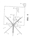
- FIG. 1 shows a printing device for monochrome and / or colored, printing on one or both sides of a ribbon-shaped carrier material, for example a paper web.
- the pressure device is of modular construction and has a feed module M1, a pressure module M2, a fixing module M3 and a post-processing module M4.
- the feed module M1 contains elements for feeding a continuous paper removed from a stacker to the printing module M2.
- This print module M2 contains the transfer station, which printed on the carrier material, which is then in the fixing module M3 fixed and cut in the post-processing module M4 and / or stacked.
- the printing module M2 contains those for printing a ribbon-shaped Carrier material 10 required with toner images Units on both sides of a transport channel 11 for the Carrier material 10 are arranged. These aggregates include essentially two differently configurable electrophotography modules E1 and E2 with associated transfer modules T1 and T2, which together form the transfer station T.
- the modules E1 and T1 are assigned to the front of the carrier material 10, the modules E2 and T2 on the back of the carrier material 10th
- the essentially identical electrophotography modules E1 and E2 contain a guided over deflection rollers 12 and preferably driven by an electric motor in the direction of the arrow seamless photoconductor tape 13, e.g. an organic Is photoconductor, also called OPC.
- seamless photoconductor tape 13 e.g. an organic Is photoconductor, also called OPC.
- OPC organic Is photoconductor
- the aggregates are outside of the photoconductor belt 13 arranged for the electrophotographic process. These aggregates serve 13 individual color separations on the photoconductor belt to generate assigned toner images.
- the Photoconductor 13 moved in the direction of the arrow initially using a Charger 14 is charged to a voltage of approximately -600 V. and depending on the characters to be printed using a consisting of an LED comb character generator 15 to about - Discharge 50 V.
- the latent thus produced, located on the photoconductor 13 Charge image is then 16/1 using developer stations up to 16/5 colored with toner. Then using the intermediate exposure device 17 the toner image is loosened and in an intermediate transfer area 18 on a transfer belt 19 of the transfer belt module T1 using a transfer corona device 20 transferred. Then the discharge corona device 21 the entire photoconductor band 13 over the unloaded entire width and via a cleaning device 22 cleaned from adhering toner dust with cleaning brushes. A subsequent intermediate exposure device 23 ensures appropriate charge conditioning of the photoconductor belt 13, which, as already described, evenly charged using the charger 14 becomes.
- the developer station contains 16/1 black toner, the developer station 16/2 color toner Yellow, the developer station 16/3 toner of magenta color, the Developer station 16/4 toner of the color cyan and for example the developer station 16/5 blue toner or toner one Spot color.
- Both single-component and as well as two-component toner developer stations be used.
- One-component toner developer stations are preferred used that work with fluidizing toner, such as this, for example, from US Patent 477106 (Applicant Fotland) are known. The subject of this U.S. patent is part of the present disclosure.
- the developer stations 16/1 to 16/5 by a single developer station creates a toner image that a single Color separation is assigned.
- This toner image is then over the transfer printing device 18 in connection with the transfer corona device 20 electrostatically on the transfer belt 19 transferred.
- the transfer module T1 contains this transfer band 19, which consists of a rubber-like substance, um several deflection devices guided and motor-driven is.
- the transfer belt 19 is similar to the photoconductor belt 13 preferably endless and without a seam.
- the transfer belt 19 in the transfer module T1 serves as a collector for the individual toner images assigned to the color separations, via the transfer device 18, 20 onto the transfer belt 19 are transmitted.
- the individual toner images are arranged one above the other so that a color image corresponding Total toner image is created.
- To the total toner image to be able to generate and then to the front of the To transfer carrier material 10 contains the transfer module T1 a switchable transfer printing station 24.
- This can, accordingly 1, several mechanically displaceable Transfer rollers 28 contain an associated transfer corona device 29. Are in the "Collect" operating state the transfer rollers 28 and the transfer corona device 29 accordingly the direction of the arrow moved upwards so that the Transfer belt 19 is spaced from the carrier material 10.
- the individual toner images are in this state by the electrophotography module E1 taken over and on the transfer belt 19 overlaid.
- the cleaning station 26 is by pivoting disabled.
- the carrier material 10 is in this Operating state in the area of the transfer printing station 24 at rest.
- the electrophotography module E2 and the transfer module T2 for the back of the record carrier 10 are corresponding the modules E1 and T1 constructed.
- a total toner image by collecting individual Generated toner images for the back, being in the operating state
- the corresponding transfer printing station 24 also "collects" here is pivoted away.
- the transfer the toner images from the transfer modules T1 and T2 the carrier material 10 thus takes place during a start-stop operation of the carrier material 10.
- the carrier material 11 is also moved in the paper conveyor belt With the help of motor-driven transport rollers 38.
- In the area between the transport rollers 38 and the transfer printing stations 24 can charge or corona devices 39 for paper conditioning be arranged so that the paper 10 before Transfer printing, e.g. is set evenly.
- the fixing module M3 serves this purpose. It contains an upper and a lower row of infrared radiators 32, between which the paper transport channel for the Carrier material 10 runs. That is both on the front as well as located on the back of the carrier material 10, toner image fixed by the infrared radiator 32 is still hot and soft and is made according to the infrared steel range 32 via a deflection roller arranged on the output side 33 guided without contact. The fixation takes place by the heat generated by the infrared radiators 32.
- the printer microprocessor-controlled control device ST which with the controlling and regulating components of feed module M1, Print module M2 and fixing module M3 or post-processing module M4 communicates. It is coupled within the modules with the individual units, e.g. with the electrophotography modules E1 and E2 and the transfer modules T1 and T2.
- a Control panel B Connected to the GS device controller or the controller ST, which can be part of the device control, is a Control panel B, through which the various operating states can be entered.
- the control panel B can have a touch screen Screen included or a personal computer with paired PC Keyboard.
- the control itself can be conventional be constructed.
- the Electrophotography modules E1 and E2 two independently of one another working, image-producing devices B1 and B2.
- the first imaging device B1 contains a character generator 15, a charging device 14, an intermediate exposure device 23, a cleaning device 22, a Unloading corotron device 21 and a developer station 16.1.
- the second imaging device B2 is analog built with charging device 14, character generator 15, a development station 16/2 and an intermediate exposure device 17.
- the developer station 16/1 can be a first Color, e.g. black, and the developer station 16/2 a second color, e.g. blue or another Colour. This makes it possible to use the electrophotography modules E1 or E2 first a first toner image Color black and this black toner image with the second imaging device B2 with a toner image overlay the additional color.
- the overlaid toner image (Spot color toner image) is then applied to the transfer modules T1 and T2 transferred and from there directly to the carrier material 10.
- the transfer modules T1 and T2 serve in both operating modes only for transferring the toner images without changing the operating mode "Collect" is necessary. However, it is also conceivable both imaging devices B1 and B2 alternately to actuate and transfer modules T1 and T2 as described at the beginning, to operate in the "Collect" operating mode.
- FIG. 3 shows an exemplary embodiment of the transfer station T, where two transfer rollers are used.
- the toner image 44 is located on the transfer belt 41 for the front of the carrier material 43.
- On the second Transfer belt 42 is the toner image 45 for the Back of the carrier material 43, which is preferably a paper web is.
- Both toner images 44 and 45 are for example using the electrophotographic devices E1 and E2 1 transferred to the transmission belts 41, 42 Service.
- a positive Toner system used i.e. after applying the toner images 44, 45 the toner particles have positive electrical charges, as indicated in Figure 3.
- the carrier material 43 is arranged, which is conveyed in the direction of arrow P1.
- the transmission bands 41, 42 can be made from one insulating material or made of a conductive material. It is desirable that the transfer belts 41, 42 and the substrate 43 the same surface speeds to have. Too much relative movement of the surfaces a mechanical blurring of the toner images 44, 45 and could have a negative impact on print quality.
- Figure 4 shows the operation of the simultaneous transfer printing when using a positive toner system. Because of the Charging corotron 47a generated electric field, the polarity that arranged on the lower transmission belt 42 Reverse toner particles, i.e. have the toner particles 46 no longer a positive charge, but a negative charge, as indicated in Figures 3 and 4. The toner particles of the toner image 44 are still positively charged. Because of the applied to the transfer rollers 49a, 49b Voltage U forms an electrostatic field F, whose field lines depend on the shape of the transfer rollers 49a, 49b, i.e. depending in particular on the radius of curvature.
- toner particles can occasionally accumulate solve early. Due to the inhomogeneity of the field and due to the increased distance between the surfaces of the carrier material 43 and the transfer belts 41, 42 the impact of the toner particles on the carrier material 43 not exactly determined; it can lead to a nebulizing effect come, which is known under the technical name "Fogging". This effect is discussed in more detail below.
- Figure 5 shows an electrical equivalent circuit, which as Circuit with series resistors R is shown.
- the flowing current i results from Ohm's law, i.e. the current i is the quotient divided by the voltage U. by the sum of the individual resistances R.
- the aim should be that the resistances R of the two transfer rollers 49a, 49b if possible are small. This can be done using conductive materials be realized, i.e. e.g. transfer rollers made of metal.
- the Resistances R of the transmission bands 41, 42 are as large as possible are so that the total current i remains small. With a large total current i becomes namely the wear of the transmission tapes 41, 42 enlarged.
- the resistance R of the transmission bands 41, 42 must, however, assume a finite value so that the electric field F with high intensity on the surface of the respective transmission bands 41, 42. is namely the resistance R of the transmission bands 41, 42 too is large, so is the effective distance for the electric field F increased; it extends from the surface of the transfer roller 49a to the surface of the transfer roller 49b. at same voltage U is then the field strength within the Field F weakened. With a certain conductivity of the Transfer bands 41, 42 is the effective distance for that electric field F between the transmission bands 41, 42 reduced and thus the field strength with otherwise the same voltage U enlarged.
- FIG. 6 shows essential parts of the transfer station T.
- a negative toner system i.e. where the charges the toner particles after being applied to the transfer belts 41, 42 are negatively charged.
- the polarity reversal is in turn caused by the transfer corotron 47a, which in this case, however, has positive potential.
- the transfer rollers 49a, 49b are driven with a voltage U, so that an electric field arises, its field strength compared to the exemplary embodiment according to FIG. 3 reverses.
- the function of the transfer printing corresponds to that described so far, only with the opposite sign of the charge and the field strength.
- Figure 7 shows the possible potential relationships on the Transfer rollers 49a, 49b.
- Figures 7a and 7b one of the transfer rollers 49a, 49b to ground.
- an electrode of the DC voltage source 40 is grounded.
- Figure 7c shows a symmetrical voltage control, wherein the center of tension is grounded.
- Figure 7d shows an asymmetrical voltage control for the transfer rollers 49a and 49b.
- FIG. 8 shows a development of the arrangement according to FIG. 3.
- the substrate 43 to be printed is transferred from the transfer rollers 49a and 49b guided so that there are the transfer rollers 49a, 49b in each case by a predetermined wrap angle wraps. This way the area in which the respective toner image 44 or 45 on the surfaces of the carrier material 43 rests, enlarged. inhomogeneities of the electric field F on its edge have less effect strong out; the fogging effect is reduced.
- Figure 9 shows an embodiment in which in the feed direction of the carrier material 43 seen in front of the transfer rollers 49a and 49b two guide rollers 49c, 49d are arranged, between which the transmission bands 41 and 42 and that Carrier material 43 are guided.
- the two guide rollers 49c and 49d are at ground potential while on the transfer rollers 49a and 49b the voltage U for generating the electric field is applied.
- the two guide rollers 49c, 49d bring the transfer belts 41 and 42 with the Carrier material 43 in contact or reduce the distance a minimum.
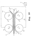
- FIG. 10 shows a detailed representation of the transfer printing area Figure 9.
- the electric field F is between the two transfer rollers 49a and 49b effective. Because of the touch of the toner particles on the transfer belts 41, 42 with the The surface of the carrier material takes place in an electrical field 41 a precise transfer printing.
- Figure 11 shows a variant of the embodiment Figure 9.
- the lower transfer roller 49b and the upper guide roller 49c are subjected to a voltage potential, so that the electric field F between the rollers 49b and 49c is effective.
- the transfer roller 49a and the Guide roller 49d are insulated and have a floating Potential. Due to the measures mentioned, it is possible to reprint required electric field F on a longer one Distance effective, so that the transfer printing process runs more gently, because the effective area on which the transfer of the Toner particles from the transfer belts 41, 42 to the Surface of the carrier material 43 takes place, is enlarged.
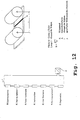
- Figure 13 shows a combination of the embodiments Figures 9 and 11.
- the feed rollers 49e and 49f carry ground potential, while the arrangement of the rollers 49a, 49b, 49c, 49d and the Potential management corresponds to that of Figure 11.
- the arrangement of the rollers 49a, 49b, 49c, 49d and the Potential management corresponds to that of Figure 11.
- the attraction of Neglect toner particles with different potential is. Early skipping of toner particles in the Area of increased distance between the transfer belts 41, 42 is avoided.
- Figure 14 shows a variant of the arrangement of Figure 9.
- the grounded guide rollers 49c, 49d are grounded Deflection bracket 49g, 49h used.
- This deflection bracket 49g, 49h can be placed near the transfer roller 49a, 49b whereby the length of contact of the transfer tapes 41, 42 shortened with the carrier material 43. If you compare them Arrangement according to FIG. 9 with that according to FIG. 14 is too recognize that in Figure 9 the minimum path in which contact between the transfer belts 41, 42 with the carrier material 43 is the sum of the radii of the transfer rollers 49a and 49b and the guide rollers 49c and 49d.
- the deflection bracket 49g, 49h with a friction-reducing Layer, e.g. with a Layer of a fluorine-containing plastic material, e.g. PFA, ETFE, FEP, PVDC, Teflon or polyimide (PI).
- a friction-reducing Layer e.g. with a Layer of a fluorine-containing plastic material, e.g. PFA, ETFE, FEP, PVDC, Teflon or polyimide (PI).
- the surface wear the deflection bracket 49g, 49h can thereby be reduced that hard, wear-resistant materials, e.g. Chrome-nickel steel, VA steel are used, or that the Deflection bracket 49g, 49h with a layer of wear-reducing Material, e.g. by nickel plating, by using silicate or by means of surface hardening.
- FIG. 15 shows the current conditions in the example according to FIG. 14, the deflection brackets 49g, 49h being at ground potential.
- the total current Iges results from the sum of the currents Ium at the transfer pressure point and the cross currents Iq1 and Iq2.
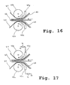
- the deflection brackets 49h, 49g can also be arranged in an electrically insulated manner so that they assume floating potential (cf. Figure 16).
- Figure 17 shows an embodiment in which the deflection bracket 49g, 49h are electrically conductive, but via a resistor R are led to ground potential. This too Embodiment according to Figure 17, the cross currents are reduced.
- FIG 18 shows a variant of the embodiment Figure 13.
- the feed rollers 49e, 49f are through deflection brackets 49i, 49j replaced.
- These deflection brackets 49i, 49j can be electrical be designed as in the examples according to the Figures 16 and 17 is indicated.
- Figure 19 shows various embodiments for the transfer rollers.
- the transfer roller is cylindrical and made of an electrically conductive metal as a solid component.
- the transfer roller is made of metal from a tube, ie hollow inside.
- the lower part of the figure in FIG. 19 shows a metallic core, which can consist of solid material or of a tube. This core is covered with a jacket made of high-resistance material.
- the use of a metallic core for the transfer roller is expedient since it has to be manufactured very precisely with little out-of-roundness. In order to minimize runout errors, the circumference of the transfer roller and the length of the transfer belt should be in an integer relationship.
- the transfer belts have a certain fluctuation in thickness, which interferes with the transfer printing process, for example local detachment of the transfer belts from the roller can occur. Therefore, an elastic coating is advantageously applied to the transfer roller, which can compensate for small mechanical tolerances of the components by elastic deformation.
- This coating should have an electrical conductivity in order to be able to build up a strong electrical field in the transfer printing zone on its outer skin.
- the electrical conductivity of the coating should be in the range from 0.5 x 10 -6 to 5 x 10 12 ⁇ cm, but preferably in the range from 0.5 x 10 5 to 5 x 10 9 ⁇ cm.
- the elastic coating should have a Shore hardness in the range from 10 to 90 Sh (A), preferably in the range from 20 to 70 Sh (A).
- the thickness of the elastic coating is 0.2 to 15 mm, preferably 0.5 to 2 mm.
- the elastic coating can additionally have a layer of fluorine-containing plastic material, preferably of PFA, ETFE, FEP, PVDC or Teflon, or of a polyimide layer.
- the additional layer can also be electrically insulating and have a maximum thickness of 40 ⁇ m, preferably from 0.1 to 20 ⁇ m.
- Conductive fillers preferably carbon black, silicates, oxides, can be added to the elastic layer, which enables an increased layer thickness.
- Figure 20 shows a transfer roller that has no continuous has metallic core, but lateral metallic contact cylinder 50.
- the central part 52 of the cylindrical The roller consists of a high-resistance material.
- the resistance R is plotted over the length 1 of the roller. It can be seen that the resistance R increases with increasing length 1 increases, whereby the local current i over the length 1 at applied voltage U drops. It thus result along the length 1 different potentials, which is undesirable.
- Figure 21 shows an embodiment of a transfer roller with a low-resistance, metallic core 56 on which one Coating 54 is applied, which is a relative high-resistance material.
- the core can also be electrical conductive plastic, e.g. from the Material PA that contains soot particles.
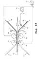
- FIG 22 In Figure 22 is a Umladekorotron Anlagen 110 with two Corotron wires 112 and with two blades Counter electrodes 114 shown.
- As an intermediate carrier is a Photoconductor tape 116 is provided. But it can also be a transfer belt be used.
- the photoconductor belt 116 with a toner image that has not yet been fixed 118, the positively charged toner particle 120 or after of the charge contains negatively charged toner particles 122 between the two corotron wires 112 and the two counter electrodes 114 performed, it being guided by deflection rollers 124 and is driven.
- the blades 114 are on one Bracket 126 attached, which is also the electrical connection to the ground potential of the printing and / or copying device 128 manufactures.
- the corotron wires 112 are on the photoconductor tape 116 opposite side surrounded by two screens 130.
- the photoconductor tape 116 is spaced in the range of 0.2 mm to 4 mm, preferably in the range from 0.2 mm to 1 mm, passed the counter electrodes 114.
- the negatively charged Toner particles 122 of the latent toner image 118 become by the electric field between the corotron wires 112 and recharged the counter electrodes 114.
- FIG. 23 shows a recharging corotron device 110 with a corotron wire 112 and a single blade used as counterelectrode 114, the field lines 132, 134 of the effective electric field being indicated.
- the counter electrode 114 has ground potential. Alternatively, the counter electrode can have a negative potential with respect to the ground potential.
- An electric field is formed between the corotron wire 112 and the counter electrode 114. This field 134 acts on the toner particles 122 which have a negative potential. The toner particles 122 are discharged as they pass the corotron wire 112 and charged to a positive potential.
- the magnitude of the potential of the now positively charged toner 120 depends on the duration of the toner in the electric field and on the density of the electric field.
- the photoconductor tape 116 is attracted by the counter electrode 114.
- ⁇ r is the dielectric constant of the air between photoconductor band 116 and counter electrode 114
- A is the surface 136 of the counter electrode 114 effective in the electric field
- U is the potential difference
- d is the distance between the underside of the photoconductor band 116 and the counter electrode 114.
- FIG. Another counter electrode 114 is shown in FIG. which is designed as a blade.
- This blade 114 has one rectangular cross section and is by a holder 126 in Printer and / or copier 128 attached.
- a blade 114 is shown, the cutting edge is jagged.
- the blade 114 is in the printer / copier 128 arranged so that the teeth 140 in the direction of the photoconductor belt 116 taper.
- the tines 140 are equidistant arranged. This arrangement ensures even transhipment of the latent toner image 118 guaranteed.
- the keeper 126 of the blade 114 is not shown in this figure 25.
- FIG. 26 shows a counter electrode 114 which consists of an arrangement of single pins 142.
- Pins 142 are arranged on a holder 126 at symmetrical intervals.
- the holder 126 is so in the printer and / or copier 128 arranged that the ends of the individual pins 142 in a parallel Level to the photoconductor tape 116 or to the corotron wire 112, and lie parallel to the corotron wire.
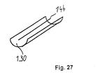
- FIG. 27 shows a counter electrode 114 which consists of there is a wire 144.
- the wire 144 is replaced by a suitable one Holding device 126 in the printer and / or copier 128 so arranged that it is in a plane parallel to the photoconductor belt 116 and parallel to the corotron wire 112.
- a screen 130 is arranged on the is the side of the wire 144 facing away from the photoconductor band 116 .
- the wire 144 is a corotron wire 112 similar wire 144 inserted.
- FIG. 28 shows a transfer printing corotron device 146 with a Corotron wire 112 and with a blade 114 Counter electrode shown.
- One more unfixed toner image 118a on the photoconductor belt 116a contains positively charged toner particles 120.
- Not yet contains fixed toner image 118b on the photoconductor belt 116b negatively charged toner particles 122.
- the photoconductor tapes 116a and 116b and a paper web 148 are between the corotron wire 112 and the blade 114 without touching them performed, the photoconductor belts 116a, 116b by deflection rollers 124 are guided and driven. The drive and the guidance of the paper web 148 is not in this figure shown.
- Corotone wire 112 has a positive potential and blade 114 has a negative potential to the ground potential.
- the corotron wire 112 is on the Photoconductor tape 116a facing away from a screen 130 surround.
- the positively charged latent toner particles 120 Toner image 118a are from the positively charged corotron wire 112 repelled and from the negatively charged toner particles 122 of the latent toner image 118b and of the negatively charged one Blade 114 tightened. Similarly, they become negative charged toner particle 122 of the latent toner image 118b of the negatively charged blade 114 and repelled by the positively charged toner particles 120 of the latent toner image 118a and attracted by the positively charged corotron wire 112.
- On the positively and negatively charged toner particles 120, 122 acts through the transfer corotron 146 a force that is greater than the binding forces between the toner particles 120, 122 and the photoconductor tapes 116a, 116b.
- the positive and negatively charged toner particles 120, 122 are replaced by the Field forces of the electric field are printed on the paper web 146.
- the toner particles remain on the paper web 146 120, 122 by the binding forces between the toner particles 120, 122 and the paper web 146 as well as by the attraction between the positively charged toner particles 120 one side of the paper and the negatively charged toner particles 122 stick on the other side of the paper.
Abstract
Description
Die Erfindung betrifft einen Drucker oder Kopierer mit einer Transferstation zum simultanen beidseitigen Bedrucken eines Trägermaterials. Ferner betrifft die Erfindung eine Korotroneinrichtung, die in der genannten Transferstation einsetzbar ist.The invention relates to a printer or copier with a Transfer station for simultaneous printing on both sides of a Support material. The invention further relates to a corotron device, which can be used in the transfer station mentioned is.
Hochleistungsdrucker und Hochleistungskopierer besitzen häufig die Fähigkeit, die Vorderseite und die Rückseite eines Trägermaterials, beispielsweise Papier, zu bedrucken. Diese Betriebsart wird auch Duplexdruck genannt. Es ist bekannt, zunächst eine Seite, beispielsweise die Vorderseite, mit einem Tonerbild zu bedrucken und anschließend das Trägermaterial zu wenden. Es wird dann erneut derselben Druckstation zugefördert, um dann die zweite Seite, üblicherweise die Rückseite, mit einem zweiten Tonerbild zu bedrucken. Diese Art des Duplexdrucks ist sowohl für bandförmiges Trägermaterial als auch für Einzelblatt-Trägermaterial bekannt. Bei einem solchen Druckbetrieb ist durch den zusätzlichen Transport und das Wenden des Trägermaterials der Gesamtdurchsatz nicht hoch. Bei einer anderen bekannten Lösung enthält ein Drucker- oder Kopiersystem zwei Druckwerke, wobei jedes Druckwerk eine Seite des Trägermaterials bedruckt. In diesem Fall wird innerhalb des Systems erheblicher Raum für die beiden Druckwerke benötigt und der technische Aufwand ist groß.High performance printers and high performance copiers often own the ability to face the front and back of a Backing material, such as paper, to be printed. This Operating mode is also called duplex printing. It is known, first a page, for example the front, with a Print the toner image and then the carrier material to turn. It is then fed again to the same printing station, around the second side, usually the back, to print with a second toner image. This kind of duplex printing is both for ribbon-shaped carrier material as well as known for single sheet carrier material. At a such printing operation is due to the additional transportation and the turning of the carrier material does not affect the total throughput high. In another known solution, a printer or copying system two printing units, each printing unit one Printed side of the carrier material. In this case, inside the system considerable space for the two printing units needed and the technical effort is great.
Bei einer aus der US-A-5,526,107 bekannten Druckeinrichtung wird Endlospapier einer Umdruckstelle eines Fotoleiterzylinders zugeführt, der auf zwei Flächen jeweils elektrofotografische Aggregate zur Erzeugung von verschiedenfarbigen Tonerbildern hat. An der Umdruckstelle wird das Endlospapier auf der Frontseite mit einer ersten Farbe bedruckt, danach wird das Endlospapier umgelenkt und einer der Umdruckstelle gegenüberliegenden Druckstelle am selben Fotoleiterzylinder zugeführt und dort mit der Rückseite bedruckt.In a printing device known from US-A-5,526,107 becomes continuous paper of a transfer location of a photoconductor cylinder fed, the electrophotographic on two surfaces Units for the generation of different colored toner images Has. The continuous paper is opened at the transfer location printed on the front with a first color, then the continuous paper is deflected and one opposite the transfer location Printing point fed to the same photoconductor cylinder and printed there with the back.
Aus der EP-A-0 320 985 ist es bekannt, ein Transferband zu verwenden, welches Tonerbilder trägt, die von einer Fotoleitertrommel auf das Transferband übertragen worden sind. Die Tonerbilder auf dem Transferband werden dann an der Umdruckstelle auf das Trägermaterial übertragen.From EP-A-0 320 985 it is known to provide a transfer belt use which carries toner images from a photoconductor drum have been transferred to the transfer belt. The Toner images on the transfer belt are then at the transfer location transferred to the carrier material.
Aus der DE-A-197 13 964, die inhaltsgleich zur US-A-5,797,077 ist, ist eine Transferstation zum gleichzeitigen Bedrucken beider Seiten eines Trägermaterials bekannt (Duplexdruck). Die Transferstation enthält eine schwenkbare Umdruckstation, die in einer ersten Stellung ein Übertragungsband vom Trägermaterial entfernt hält, so daß keine Tonerbilder auf dieses Trägermaterial übertragen werden. In dieser Stellung werden auf dem Übertragungsband Tonerbilder überlagernd erzeugt, um einen Mehrfarbendruck zu ermöglichen. In einer zweiten Stellung ist die Umdruckstation an das Trägermaterial angeschwenkt und überträgt das mehrfarbige Tonerbild.From DE-A-197 13 964, the same content as US-A-5,797,077 is a transfer station for simultaneous printing known on both sides of a carrier material (duplex printing). The transfer station contains a swiveling transfer printing station, in a first position a transfer belt from the carrier material stops so that no toner images on it Carrier material are transferred. Be in this position generated on the transfer belt overlaying toner images to enable multi-color printing. In a second position the transfer station is pivoted to the carrier material and transfers the multi-color toner image.
In der WO 87/02792 ist eine Korotroneinrichtung mit einer Korotronelektrode beschrieben, deren Gegenelektrode als Metallplatte ausgeführt ist. Diese Metallplatte liegt auf Massepotential. Das zwischen der Korotronelektrode und der Gegenelektrode erzeugte elektrische Feld führt zu einer Ladungsbeeinflussung der Tonerpartikel.WO 87/02792 describes a corotron device with a corotron electrode described, the counter electrode as a metal plate is executed. This metal plate is at ground potential. That between the corotron electrode and the counter electrode generated electric field leads to an influence on the charge the toner particles.
Es ist Aufgabe der Erfindung einen Drucker oder Kopierer zu schaffen, der ein gleichzeitiges Bedrucken von Vorderseite und Rückseite eines Trägermaterials bei geringem Aufwand und mit hoher Druckqualität ermöglicht. It is an object of the invention to provide a printer or copier create a simultaneous printing from the front and back of a carrier material with little effort and with high print quality.
Diese Aufgabe wird durch die Merkmale des Anspruchs 1 gelöst.
Vorteilhafte Weiterbildungen sind in den abhängigen Ansprüchen
angegeben.This object is solved by the features of
Gemäß der Erfindung stehen sich an der Umdruckstelle zwei übertragungsbänder gegenüber, deren Tonerteilchen unterschiedliche Polarität haben. Es wird nun ein elektrostatisches Feld erzeugt, das so gerichtet ist, daß die Tonerteilchen sowohl vom ersten Übertragungsband als auch vom zweiten Übertragungsband abgestoßen werden und sich auf den jeweiligen Oberflächen des Trägermaterials anlagern. Auf diese Weise wird ein gleichzeitiges Umdrucken erreicht. Der Transportweg des Trägermaterials bleibt kurz, da das Trägermaterial nicht an zwei Druckstationen bzw. an einer Druckstation zweimal vorbeigeführt werden muß. Zusätzlich entfällt eine Zwischenfixierung der auf das Trägermaterial übertragenen Tonerbilder, wodurch sich der technische Aufwand verringert und die Druckqualität hoch bleibt.According to the invention there are two at the transfer location transfer belts opposite, the toner particles different Have polarity. It now becomes an electrostatic one Generates field that is directed so that the toner particles both from the first transmission band and from the second Transfer belt are repelled and affect the respective Attach the surfaces of the carrier material. In this way a simultaneous transfer printing is achieved. The route of transportation of the carrier material remains short because the carrier material is not at two printing stations or twice at one printing station must be passed. There is also no intermediate fixation the toner images transferred to the carrier material, which reduces the technical effort and the Print quality remains high.
Bei einem bevorzugten Ausführungsbeispiel haben beide Übertragungsbänder in Zuführrichtung des Trägermaterials gesehen in einem Abschnitt vor der Umdruckstelle Tonerbilder mit Tonerteilchen gleicher Polarität, wobei vor der Umdruckstelle längs eines der übertragungsbänder ein Umladekorotron angeordnet ist, welches ein elektrisches Feld erzeugt, das die Polarität der Tonerteilchen auf diesem Übertragungsband durch Umladen umkehrt. Durch diese Maßnahmen kann für beide Ubertragungsbänder ein einheitliches Tonersystem, beispielsweise ein positives oder negatives Tonerystem mit positiver bzw. negativer Ladung des Tonerbildes, verwendet werden. Demgemäß ist die Druckqualität auf beiden Seiten des Trägermaterials nahezu identisch. In a preferred embodiment, both have transmission bands seen in the feed direction of the carrier material in a section in front of the transfer point, toner images with toner particles same polarity, before the transfer point A transfer corotron is arranged along one of the transfer belts is which creates an electric field that the Polarity of the toner particles on this transfer belt Reloading reverses. These measures can be used for both transmission bands a uniform toner system, for example a positive or negative toner system with positive or negative charge of the toner image can be used. Accordingly, is the print quality on both sides of the substrate almost identical.
Ein anderes Ausführungsbeispiel ist dadurch gekennzeichnet, daß sich an der Umdruckstelle zwei übertragungswalzen gegenüberstehen, und daß an die Übertragungswalzen eine Gleichspannung angelegt ist, die das elektrische Feld zum Umdrucken der Tonerteilchen erzeugt. Die Übertragungswalzen gewährleisten einerseits eine präzise Führung des Trägermaterials und der Übertragungsbänder im Bereich der Umdruckstelle. Andererseits ermöglichen sie auf einfache Weise den Aufbau eines elektrischen Feldes im Bereich der Umdruckstelle.Another embodiment is characterized in that that two transfer rollers face each other at the transfer location, and that to the transfer rollers a DC voltage is created, which is the electric field for transfer printing which creates toner particles. Ensure the transfer rollers on the one hand a precise guidance of the carrier material and the transfer belts in the area of the transfer printing point. on the other hand allow you to easily build a electrical field in the area of the transfer printing point.
In der Praxis hat sich ein Ausführungsbeispiel bewährt, bei dem in Zuführrichtung des Trägermaterials gesehen vor den Übertragungswalzen zwei Führungselemente angeordnet sind, zwischen denen die Übertragungsbänder und das Trägermaterial geführt ist. Auf diese Weise werden die übertragungsbänder und das Trägermaterial längs einer relativ großen Wegstrecke unter gegenseitiger Berührung geführt. An der Umdruckstelle wird der Fogging-Effekt reduziert, da die Tonerteilchen nur einen geringen oder keinen Abstand zur Oberfläche des Trägermaterials haben und so ein ortsgenaues Umdrucken erfolgt'.In practice, an embodiment has proven itself in seen in the feed direction of the carrier material before Transfer rollers two guide elements are arranged between which the transfer tapes and the carrier material is led. In this way, the transfer belts and the carrier material along a relatively large distance led by mutual contact. At the transfer location the fogging effect is reduced because the toner particles only a little or no distance from the surface of the carrier material have and so a precise transfer printing takes place '.
Gemäß einem weiteren Aspekt der Erfindung wird eine Korotroneinrichtung
mit den Merkmalen des Anspruchs 25 angegeben.
Diese Korotroneinrichtung läßt sich vorteilhaft in Verbindung
mit den genannten Transfermodulen verwenden.According to a further aspect of the invention, a corotron device
indicated with the features of
Zum Bedrucken eines Endbildträgers, z.B. Papier, wird ein Transfer eines auf einem Zwischenträger vorhandenen Tonerbildes auf den Endbildträger mechanisch, thermodynamisch oder elektrostatisch vorgenommen. Für einen elektrostatischen Transfer des Tonerbildes von einem Fotoleiterband auf einen Zwischenträger oder auf einen Endbildträger müssen die Tonerpartikel ein gewisses Spannungspotential besitzen. Der elektrostatische Transfer der Tonerpartikel erfolgt durch Kräfte im elektrischen Feld und beruht auf einer Potentialdifferenz zwischen den Tonerpartikeln und dem Endbildträger, auf den das Tonerbild übertragen werden soll. Die Kraft durch das elektrische Feld muß dabei größer sein als die Bindungskräfte, durch die die Tonerpartikel an dem Zwischenträger für Tonerbilder, von dem sie zu transferieren sind, gehalten werden.For printing on a final image carrier, e.g. Paper, becomes a Transfer of a toner image on an intermediate carrier on the final image carrier mechanically, thermodynamically or made electrostatically. For an electrostatic Transfer the toner image from a photoconductor belt to one The toner particles must be on an intermediate carrier or on a final image carrier have a certain potential for tension. The electrostatic The toner particles are transferred by forces in the electric field and is based on a potential difference between the toner particles and the final image carrier on which the toner image is to be transferred. The power through that electrical field must be greater than the binding forces, through which the toner particles on the intermediate carrier for Toner images from which they are to be transferred are held.
In elektrografischen Druck- und/oder Kopiereinrichtungen werden Trockentonerpartikel zum elektrografischen Transfer mit einem geeigneten Spannungspotential eingesetzt, so daß der Transfer der Tonerpartikel auf ein Material ohne zusätzliche Ladungsbeeinflussung der Tonerpartikel im Drucker oder Kopierer durchgeführt werden kann. Soll der Endbildträger auf beiden Seiten bedruckt werden (Duplexdruck), muß der Endbildträger gewendet werden, oder es erfolgt ein gleichzeitiger oder zeitversetzter Transfer der Tonerpartikel von beiden Seiten auf den Endbildträger. Um den Transfer ohne Zwischenfixierung des auf den Endbildträger übertragenen Tonerbildes zu realisieren, müssen die Tonerpartikel auf der ersten Seite des Zwischenträgers zu den Tonerpartikeln der zweiten Seite eine Potentialdifferenz aufweisen. Vorzugsweise werden die Tonerpartikel von einem positiven Spannungspotential zu einem negativen Spannungspotential, in bezug auf das Massepotential, umgeladen. Somit können die Tonerpartikel gleichzeitig oder zeitversetzt ohne Zwischenfixierung von dem Zwischenträger auf den Endbildträger von beiden Seiten übertragen werden. Die Tonerpartikel auf beiden Seiten des Endbildträgers ziehen sich durch ihre unterschiedlichen Potentiale durch den Endbildträger hindurch an und/oder werden durch die Potentialdifferenz zum Endbildträger angezogen, so daß sie auf dem Endbildträger haften.In electrographic printing and / or copying facilities Dry toner particles for electrographic transfer with a suitable voltage potential, so that the Transfer the toner particles to a material without additional Charge influence of the toner particles in the printer or copier can be carried out. Should the final image carrier on both Pages are printed (duplex printing), the final image carrier must be turned, or there is a simultaneous or time-delayed transfer of the toner particles from both sides on the final image carrier. To transfer without intermediate fixation to realize the toner image transferred to the final image carrier, the toner particles on the first page of the Intermediate carrier to the toner particles of the second side Show potential difference. Preferably the toner particles from a positive potential to a negative potential Voltage potential, in relation to the ground potential, transhipped. Thus, the toner particles can be simultaneously or staggered in time without intermediate fixation of the intermediate carrier be transferred from both sides to the final image carrier. Pull the toner particles on both sides of the final image carrier different potentials through the final image carrier through and / or through the potential difference attracted to the final image carrier so that they on the Final image carriers stick.
Nach dem Transferprozeß bleiben Tonerpartikel an dem Zwischenträger, von dem sie zu transferieren sind, haften, d.h. sie sind nicht erfolgreich transferiert worden. Es handelt sich dabei um Tonerpartikel von wenigen Prozent des Tonerbildes, meist erheblich weniger als 20 Prozent. Diese nicht transferierten Tonerpartikel besitzen meist ein geringes oder falsches Spannungspotential. Um einen weiteren Transfer dieser nicht transferierten Tonerpartikel, z.B. zum Reinigen des Zwischenträgers, mit einem hohen Wirkungsgrad durchzuführen, ist es notwendig, die Tonerpartikel auf ein definiertes Potential aufzuladen. Dieser Ladevorgang erfolgt mit einer Korotroneinrichtung. Der Zwischenträger bildet dabei die Gegenelektrode zu der Korotroneinrichtung. Handelt es sich bei dem Zwischenträger um ein leitfähiges Material, mit einem spezifischen Widerstand von kleiner 106 Ohm cm, so wird der Zwischenträger auf Massepotential oder auf ein anderes geeignetes Spannungspotential gelegt und dient dadurch als Gegenelektrode. Ist der Zwischenträger z.B. im Falle eines Fotoleiters mit einer lichtempfindlichen Deckschicht versehen, dessen Dunkelwiderstand sehr hochohmig ist (z.B. größer 106 Ohm cm), muß eine Gegenelektrode auf der Rückseite des Zwischenträgers angeordnet werden. Gegenelektroden sind vorzugsweise als Metallplatten oder als leitfähige Umlenkwalzen ausgeführt. Da Umlenkwalzen mit einem hohen mechanischen Aufwand, erhöhten Platzbedarf und hohen Kosten verbunden sind, werden vorrangig Metallplatten als Gegenelektroden eingesetzt.After the transfer process, toner particles adhere to the intermediate carrier from which they are to be transferred, ie they have not been successfully transferred. These are toner particles of a few percent of the toner image, usually considerably less than 20 percent. These untransferred toner particles usually have a low or incorrect voltage potential. In order to carry out a further transfer of these untransferred toner particles, for example for cleaning the intermediate carrier, with high efficiency, it is necessary to charge the toner particles to a defined potential. This loading process takes place with a corotron device. The intermediate carrier forms the counter electrode to the corotron device. If the intermediate carrier is a conductive material with a specific resistance of less than 10 6 ohm cm, the intermediate carrier is connected to ground potential or to another suitable voltage potential and thus serves as a counter electrode. If, for example in the case of a photoconductor, the intermediate carrier is provided with a light-sensitive cover layer whose dark resistance is very high-impedance (for example greater than 10 6 ohm cm), a counter electrode must be arranged on the back of the intermediate carrier. Counter electrodes are preferably designed as metal plates or as conductive deflection rollers. Since deflection rollers are associated with a high mechanical outlay, increased space requirement and high costs, metal plates are primarily used as counter electrodes.
Die Gegenelektrode soll einen geringen Übergangswiderstand zu dem Zwischenträger besitzen. Der Zwischenträger wird an der feststehenden Gegenelektrode berührungslos vorbeigeführt. Um den geringen Übergangswiderstand zu erzielen, muß der Zwischenträger in einem geringen Abstand an der festen Gegenelektrode vorbeigeführt werden. Dieser Abstand beträgt vorzugsweise 0,2 mm bis 1,0 mm. Die Kräfte zwischen zwei Körpern, durch deren Potentialdifferenz ein elektrisches Feld erzeugt wird, sind mit den Kräften zwischen zwei Platten eines Plattenkondensators vergleichbar, wobei eine Platte des Plattenkondensators durch die Gegenelektrode und die andere Platte durch die Unterseite des Zwischenträgers gebildet wird. Auf den Zwischenträger wirkt dann eine Kraft in Richtung der feststehenden Gegenelektrode. Diese Kraft führt dazu, daß der bandförmige Zwischenträger an der Gegenelektrode in deren Richtung auslenkt, sie berührt und ihr anhaftet. Durch den Kontakt zwischen dem bewegten bandförmigen Zwischenträger und der feststehenden Gegenelektrode entsteht Haft- und Gleitreibung. Die zusätzlich zum Antrieb des Zwischenträgers durch diese Reibung zwischen dem Zwischenträger und Gegenelektrode benötigte mechanische Energie muß von der Antriebseinheit des Zwischenträgers aufgebracht werden. Außerdem wird infolge der Gleitreibung der Zwischenträger und/oder die Gegenelektrode abgenutzt.The counter electrode should have a low contact resistance own the intermediate carrier. The intermediate carrier is on the fixed counter electrode passed without contact. Around The intermediate carrier must achieve the low contact resistance at a short distance on the fixed counter electrode to be led past. This distance is preferably 0.2 mm to 1.0 mm. The forces between two bodies an electric field due to their potential difference generated are one with the forces between two plates Plate capacitor comparable, with a plate of the Plate capacitor through the counter electrode and the other Plate formed by the underside of the intermediate carrier becomes. A force in the direction then acts on the intermediate carrier the fixed counter electrode. This force leads to the fact that the band-shaped intermediate carrier on the counter electrode deflects in their direction, touches it and clings to it. Through the contact between the moving band-shaped Intermediate carrier and the fixed counter electrode is created Static and sliding friction. The in addition to the drive of the intermediate carrier due to this friction between the intermediate carrier and counterelectrode required mechanical energy must be from the Drive unit of the intermediate carrier are applied. Moreover becomes the intermediate carrier due to the sliding friction and / or the counter electrode is worn.
Aufgabe ist es daher, eine Korotroneinrichtung anzugeben, bei der zwischen dem Zwischenträger für Tonerbilder und der Gegenelektrode geringe Anziehungskräfte auftreten und der Ladungsträgeraustausch gewährleistet ist.The task is therefore to specify a corotron device at between the intermediate support for toner images and the counter electrode low attraction forces occur and the charge carrier exchange is guaranteed.
Gemäß der neuartigen Korotroneinrichtung hat die Gegenelektrode leitende Erhebungen, deren Endpunkte in Richtung des Korotrondrahtes ragen und die in einer Ebene parallel zur Längsachse des Korotrondrahtes liegen. Durch diese Ausbildung der Gegenelektrode wird erreicht, daß die Anziehungskraft zwischen dem Zwischenträger und der Gegenelektrode erheblich verringert ist. Diese Anziehungskraft hängt entscheidend von der wirksamen Fläche ab. Die maßgebende wirksame Fläche ist die dem Zwischenträger zugewandte Fläche der Gegenelektrode. Durch die Anordnung von elektrisch leitenden Erhebungen, deren Endpunkte die maßgebende wirksame Fläche darstellen, ist gewährleistet, daß die wirksame Fläche und somit auch die Anziehungskräfte zwischen dem Zwischenträger und der Gegenelektrode gering sind. Durch diese Anordnung wird auch erreicht, daß durch die Krümmungen an den Erhebungen es zu einem verstärkten Austausch von Ladungsträgern infolge von Spitzenentladung kommt.According to the new corotron device, the counter electrode leading surveys, the endpoints of which are towards the Corotron wire protrude and in a plane parallel to Longitudinal axis of the corotron wire. Through this training the counter electrode is achieved that the attractive force between the intermediate carrier and the counter electrode considerably is reduced. This attraction depends crucially on the effective area. The relevant effective area is the surface of the counter electrode facing the intermediate carrier. By arranging electrically conductive elevations, the Endpoints are the relevant effective area ensures that the effective area and thus also the attractive forces between the intermediate carrier and the counter electrode are low. This arrangement also achieves that the curvatures on the elevations intensified it Exchange of carriers due to peak discharge comes.
Eine bevorzugte Ausführungsform sieht vor, daß die Erhebungen der Gegenelektrode entlang der Längsachse des Korotrondrahtes angeordnet sind. Dadurch wird erreicht, daß das elektrische Feld zum Beeinflussen der Ladung der Tonerpartikel gleichmäßig ausgebildet und die Anordnung der Gegenelektrode platzsparend möglich ist.A preferred embodiment provides that the surveys the counter electrode along the longitudinal axis of the corotron wire are arranged. This ensures that the electrical Field for influencing the charge of the toner particles evenly trained and the arrangement of the counter electrode to save space is possible.
Eine weitere Ausführungsform ist dadurch gekennzeichnet, daß die Gegenelektrode als Erhebungen Einzelstifte enthält. Dadurch wird erreicht, daß die Gegenelektrode aus standardisierten Bauteilen kostengünstig hergestellt werden kann.Another embodiment is characterized in that the counter electrode contains individual pins as elevations. Thereby it is achieved that the counter electrode from standardized Components can be manufactured inexpensively.
Eine weitere bevorzugte Ausführungsvariante besteht darin, daß die Gegenelektrode spitz zulaufende Erhebungen enthält. Dadurch wird erreicht, daß die wirksame Fläche der Gegenelektrode und somit die Anziehungskraft zwischen dem Zwischenträger für Tonerbilder und Gegenelektrode weiter herabgesetzt wird.Another preferred embodiment variant consists in that the counter electrode contains tapered bumps. This ensures that the effective area of the counter electrode and thus the attraction between the intermediate carrier for toner images and counterelectrode further reduced becomes.
Gemäß einem weiteren Aspekt ist bei einer Korotroneinrichtung für eine elektrografische Druck- und/oder Kopiereinrichtung vorgesehen, daß die Gegenelektrode nach Art einer Klinge mit einer Schneide ausgebildet ist, wobei die Schneide parallel zur Längsachse des Korotrondrahtes angeordnet ist. Mit dieser Ausgestaltung wird erreicht, daß z.B. eine Blechplatte, die senkrecht zum Zwischenträger für Tonerbilder angeordnet ist und über die Breite des Zwischenträgers für Tonerbilder verläuft, als Gegenelektrode eingesetzt wird. Eine solche Anordnung ist platzsparend und kostengünstig. Durch diese Anordnung wird auch erreicht, daß es durch die Krümmungen an der Schneide zu einem selbständigen Austausch von Ladungsträgern (zu einer Spitzenentladung) kommt. According to a further aspect, a corotron device for an electrographic printing and / or copying device provided that the counter electrode in the manner of a blade with a cutting edge is formed, the cutting edge being parallel is arranged to the longitudinal axis of the corotron wire. With this Design is achieved that e.g. a sheet metal plate, which are arranged perpendicular to the intermediate carrier for toner images is and across the width of the intermediate carrier for toner images runs, is used as a counter electrode. Such an arrangement is space-saving and inexpensive. By this arrangement is also achieved by the curvatures the cutting edge for an independent exchange of load carriers (to a peak discharge).
Eine weitere günstige Ausgestaltungsform der Korotroneinrichtung sieht vor, daß die Schneide der Gegenelektrode gezackt ist und daß sich die Zacken in Richtung des Korotrondrahtes verjüngen, so daß die Endpunkte und/oder Endflächen der Zakken in Richtung des Korotrondrahtes ragen und parallel zur Längsachse des Korotrondrahtes liegen. Dadurch wird erreicht, daß die wirksame Fläche, von der der Betrag der Anziehungskraft zwischen dem Zwischenträger für Tonerbilder und Gegenelektrode abhängig ist, gegenüber der durchgehenden Klinge herabgesetzt ist, wodurch die Anziehungskraft weiter verringert wird. Die Spitzenentladung wird weiter begünstigt.Another cheap embodiment of the corotron device provides that the cutting edge of the counter electrode is serrated is and that the prongs are in the direction of the corotron wire taper so that the end points and / or end faces of the zakken protrude in the direction of the corotron wire and parallel to Longitudinal axis of the corotron wire. This ensures that the effective area from which the amount of attraction between the intermediate carrier for toner images and counter electrode is dependent on the continuous blade is reduced, which further reduces the attraction becomes. The peak discharge is further favored.
Gemäß einem weiteren Aspekt ist bei einer Korotroneinrichtung für eine elektrografische Druck- und/oder Kopiereinrichtung vorgesehen, daß die Gegenelektrode durch einen Draht ausgebildet ist, dessen Längsachse parallel zur Längsachse des Korotrondrahtes angeordnet ist. Mit dieser Ausgestaltung wird erreicht, daß z.B. auch ein Korotrondraht als Gegenelektrode angeordnet wird. Dieser Draht verläuft über Breite des Zwischenträgers. Eine solche Anordnung ist platzsparend und reduziert die Anzahl der eingesetzten Bauteile.According to a further aspect, a corotron device for an electrographic printing and / or copying device provided that the counter electrode is formed by a wire is, whose longitudinal axis is parallel to the longitudinal axis of the Corotron wire is arranged. With this configuration achieves that e.g. also a corotron wire as a counter electrode is arranged. This wire runs across the width of the intermediate carrier. Such an arrangement is space-saving and reduced the number of components used.
Ausführungsbeispiele der Erfindung werden im folgenden anhand der Zeichnungen erläutert. Darin zeigt
Figur 1- eine schematische Schnittdarstellung eines elektrofotografischen Druckgeräts zum monochromen und/oder farbigen, ein- oder beidseitigen Bedrucken eines bandförmigen Trägermaterials, bei dem die Transferstation nach der Erfindung eingesetzt werden kann,
Figur 2- eine schematische Schnittdarstellung eines Druckgeräts nach Figur 1, welches das Trägermaterial beidseitig bedruckt,
Figur 3- schematisch eine Anordnung wesentlicher Teile der Transferstation mit Umladung der Tonerteilchen,
Figur 4- eine Detaildarstellung der Anordnung nach Figur 3 zur Erläuterung der Wirkungsweise,
- Figur 5
- ein elektrisches Ersatzschaltbild, das die Widerstandsverhältnisse und Stromverhältnisse an der Umdruckstelle wiedergibt,
- Figur 6
- eine Anordnung ähnlich der nach Figur 3 mit negativem Tonersystem,
Figur 7- schematisch die möglichen Potentialverhältnisse an den Umdruckwalzen,
- Figur 8
- ein Ausführungsbeispiel, bei dem die Übertragungsbänder die Übertragungswalzen teilweise umschlingen,
- Figur 9
- ein Ausführungsbeispiel mit Führungswalzen,
Figur 10- eine Detaildarstellung der Anordnung nach Figur 9,
Figur 11- eine Anordnung ähnlich der nach Figur 9, bei der das zum Umdrucken erforderliche elektrische Feld zwischen der Führungswalze und der Übertragungswalze aufgebaut wird,
Figur 12- ein elektrisches Ersatzschaltbild zum Ausführungsbeispiel nach Figur 11,
Figur 13- eine
Anordnung nach Figur 11, wobei zusätzlich Zuführwalzen vorgesehen sind, Figur 14- ein Ausführungsbeispiel mit Umlenkbügeln,
Figur 15- die Stromverhältnisse beim Ausführungsbeispiel nach Figur 14,
- Figur 16
- das
Ausführungsbeispiel nach Figur 14 mit isolierten Umlenkbügeln, Figur 17- ein Ausführungsbeispiel mit elektrisch leitenden Umlenkbügeln, die über einen Widerstand gegen Massepotential geführt sind,
Figur 18- ein Ausführungsbeispiel ähnlich
dem nach Figur 13, Figur 19- mehrere Ausführungsbeispiele für eine Übertragungswalze,
Figur 20- eine Übertragungswalze aus einem hochohmigen Material mit seitlichen Elektrodenanschlüssen,
Figur 21- eine Übertragungswalze mit einem elektrisch leitenden Kern und einer hochohmigen Beschichtung,
Figur 22- eine Umladekorotroneinrichtung mit zwei Korotrondrähten und mit zwei als Klingen ausgebildeten Gegenelektroden,
Figur 23- ein Umladekorotron mit einem Korotrondraht und einer als Gegenelektrode eingesetzten Klinge, wobei die Feldlinien des wirksamen elektrischen Feldes angedeutet sind,
Figur 24- die Darstellung einer Gegenelektrode, die als Klinge ausgeführt ist,
Figur 25- die Darstellung einer Klinge, wobei die Schneide gezackt ist,
Figur 26- die Darstellung einer Gegenelektrode, die aus einer Anordnung von Einzelstiften besteht,
Figur 27- die Darstellung einer Gegenelektrode, die aus einem Draht besteht, und
Figur 28- eine Umdruckkorotroneinrichtung mit einem Korotrondraht und mit einer als Klinge ausgebildeten Gegenelektrode.
- Figure 1
- 2 shows a schematic sectional illustration of an electrophotographic printing device for monochrome and / or colored printing on one or both sides of a strip-shaped carrier material, in which the transfer station according to the invention can be used,
- Figure 2
- 2 shows a schematic sectional illustration of a printing device according to FIG. 1, which prints the carrier material on both sides,
- Figure 3
- schematically an arrangement of essential parts of the transfer station with transfer of the toner particles,
- Figure 4
- 3 shows a detailed representation of the arrangement according to FIG. 3 to explain the mode of operation,
- Figure 5
- an electrical equivalent circuit diagram that shows the resistance and current conditions at the transfer location,
- Figure 6
- an arrangement similar to that of Figure 3 with a negative toner system,
- Figure 7
- schematically the possible potential relationships on the transfer rollers,
- Figure 8
- an embodiment in which the transfer belts partially wrap around the transfer rollers,
- Figure 9
- an embodiment with guide rollers,
- Figure 10
- 9 shows a detailed representation of the arrangement according to FIG. 9,
- Figure 11
- an arrangement similar to that according to FIG. 9, in which the electric field required for transfer printing is built up between the guide roller and the transfer roller,
- Figure 12
- an electrical equivalent circuit diagram to the embodiment of Figure 11,
- Figure 13
- 11 shows an arrangement according to FIG. 11, feed rollers additionally being provided,
- Figure 14
- an embodiment with deflection brackets,
- Figure 15
- the current conditions in the embodiment of Figure 14,
- Figure 16
- the embodiment of Figure 14 with insulated deflection brackets,
- Figure 17
- an embodiment with electrically conductive deflection brackets, which are guided via a resistance to ground potential,
- Figure 18
- an embodiment similar to that of Figure 13,
- Figure 19
- several embodiments for a transfer roller,
- Figure 20
- a transfer roller made of a high-resistance material with side electrode connections,
- Figure 21
- a transfer roller with an electrically conductive core and a high-resistance coating,
- Figure 22
- a recharging corotron device with two corotron wires and with two counter electrodes designed as blades,
- Figure 23
- a recharging corotron with a corotron wire and a blade used as a counter electrode, the field lines of the effective electric field being indicated,
- Figure 24
- the representation of a counter electrode, which is designed as a blade,
- Figure 25
- the representation of a blade with the cutting edge serrated,
- Figure 26
- the representation of a counter electrode, which consists of an arrangement of individual pins,
- Figure 27
- the representation of a counter electrode, which consists of a wire, and
- Figure 28
- a transfer printing corotron device with a corotron wire and with a counter electrode designed as a blade.
Figur 1 zeigt ein Druckgerät zum monochromen und/oder farbigen, ein- oder beidseitigen Bedrucken eines bandförmigen Trägermaterials, beispielsweise einer Papierbahn. Das Druckgerät ist modular aufgebaut und hat ein Zuführmodul M1, ein Druckmodul M2, ein Fixiermodul M3 und ein Nachverarbeitungsmodul M4. Das Zuführmodul M1 enthält Elemente zur Zuführung eines von einem Stapler abgezogenen Endlospapiers zum Druckmodul M2. Dieses Druckmodul M2 enthält die Transferstation, welche das Trägermaterial bedruckt, das anschließend im Fixiermodul M3 fixiert und im Nachverarbeitungsmodul M4 geschnitten und/oder gestapelt wird.FIG. 1 shows a printing device for monochrome and / or colored, printing on one or both sides of a ribbon-shaped carrier material, for example a paper web. The pressure device is of modular construction and has a feed module M1, a pressure module M2, a fixing module M3 and a post-processing module M4. The feed module M1 contains elements for feeding a continuous paper removed from a stacker to the printing module M2. This print module M2 contains the transfer station, which printed on the carrier material, which is then in the fixing module M3 fixed and cut in the post-processing module M4 and / or stacked.
Das Druckmodul M2 enthält die für das Bedrucken eines bandförmigen
Trägermaterials 10 mit Tonerbildern erforderlichen
Aggregate, die beidseitig eines Transportkanals 11 für das
Trägermaterial 10 angeordnet sind. Diese Aggregate umfassen
im wesentlichen zwei verschieden konfigurierbare Elektrofotografiermodule
E1 und E2 mit zugehörigen Transfermodulen T1
und T2, die zusammen die Transferstation T bilden. Die Module
E1 und T1 sind der Vorderseite des Trägermaterials 10 zugeordnet,
die Module E2 und T2 der Ruckseite des Trägermaterials
10.The printing module M2 contains those for printing a ribbon-shaped
Die im wesentlichen identisch aufgebauten Elektrofotografiemodule
E1 und E2 enthalten ein über Umlenkwalzen 12 geführtes
und elektromotorisch in Pfeilrichtung angetriebenes, vorzugsweise
nahtloses Fotoleiterband 13, das z.B. ein organischer
Fotoleiter, auch OPC genannt, ist. Entlang der lichtempfindlichen
Außenseite des Fotoleiterbandes 13 sind die Aggregate
für den elektrofotografischen Prozeß angeordnet. Diese Aggregate
dienen dazu, auf dem Fotoleiterband 13 einzelnen Farbauszügen
zugeordnete Tonerbilder zu erzeugen. Hierzu wird der
in Pfeilrichtung bewegte Fotoleiter 13 zunächst mithilfe einer
Ladeeinrichtung 14 auf eine Spannung von ca. -600 V aufgeladen
und abhängig von zu druckenden Zeichen mithilfe eines
aus einem LED-Kamm bestehenden Zeichengenerators 15 auf etwa
- 50 V entladen.The essentially identical electrophotography modules
E1 and E2 contain a guided over
Das so erzeugte, auf dem Fotoleiter 13 befindliche latente
Ladungsbild wird dann mithilfe von Entwicklerstationen 16/1
bis 16/5 mit Toner eingefärbt. Danach wird mithilfe der Zwischenbelichtungseinrichtung
17 das Tonerbild gelockert und in
einem Zwischenumdruckbereich 18 auf ein Übertragungsband 19
des Transferbandmoduls T1 mithilfe einer Übertragungskoronaeinrichtung
20 übertragen. Danach wird mithilfe der Entladekoronaeinrichtung
21 das gesamte Fotoleiterband 13 über die
gesamte Breite entladen und über eine Reinigungseinrichtung
22 mit Reinigungsbürsten von anhaftendem Tonerstaub gereinigt.
Eine nachfolgende Zwischenbelichtungseinrichtung 23
sorgt für eine entsprechende ladungsmäßige Konditionierung
des Fotoleiterbandes 13, welches dann, wie bereits beschrieben,
mithilfe der Ladeeinrichtung 14 gleichmäßig aufgeladen
wird.The latent thus produced, located on the
Mittels des Elektrofotografiemoduls E1 bzw. E2 werden einzelnen Farbauszügen zugeordnete Tonerbilder erzeugt, deren Gesamtheit das zu druckende Farbbild bildet. Hierzu sind die Entwicklerstationen 16/1 bis 16/5 schaltbar ausgebildet. Sie enthalten jeweils den einem einzelnen Farbauszug zugeordneten Toner. Beispielsweise enthält die Entwicklerstation 16/1 schwarzen Toner, die Entwicklerstation 16/2 Toner der Farbe Gelb, die Entwicklerstation 16/3 Toner der Farbe Magenta, die Entwicklerstation 16/4 Toner der Farbe Cyan und beispielsweise die Entwicklerstation 16/5 blauen Toner oder Toner einer Sonderfarbe. Als Entwicklerstationen können sowohl Einkomponenten- als auch Zweikomponenten-Toner-Entwicklerstationen verwendet werden. Vorzugsweise werden Einkomponenten-Toner-Entwicklerstationen eingesetzt, die mit Fluidizing-Toner arbeiten, wie diese beispielsweise aus dem US-Patent 477106 (Anmelder Fotland) bekannt sind. Der Gegenstand dieses US-Patentes ist Bestandteil der vorliegenden Offenbarung.Using the electrophotography module E1 or E2 individual Color separations associated with toner images generated, their entirety forms the color image to be printed. For this are the Developer stations 16/1 to 16/5 switchable. she each contain the one assigned to a single color separation Toner. For example, the developer station contains 16/1 black toner, the developer station 16/2 color toner Yellow, the developer station 16/3 toner of magenta color, the Developer station 16/4 toner of the color cyan and for example the developer station 16/5 blue toner or toner one Spot color. Both single-component and as well as two-component toner developer stations be used. One-component toner developer stations are preferred used that work with fluidizing toner, such as this, for example, from US Patent 477106 (Applicant Fotland) are known. The subject of this U.S. patent is part of the present disclosure.
Um die Schaltbarkeit der Entwicklerstationen zu erreichen,
d.h. um jede einzelne Entwicklerstation individuell betätigen
zu können, können diese Stationen bei der Verwendung von
Fluidizing-Toner entsprechend der deutschen Patentanmeldung
DE 196 52 866 ausgebildet sein. Das Schalten der Entwicklerstation
erfolgt demgemäß durch Änderung der elektrischen Vorspannung
der Transferwalze bzw. durch Änderung der elektrischen
Vorspannung der Applikatorwalze. Es ist außerdem möglich,
die Entwicklerstationen dadurch zu schalten, daß sie
mechanisch verschoben und dadurch in Kontakt mit dem Fotoleiterband
13 gebracht werden. Ein derartiges Prinzip ist z.B.
aus der DE-A-196 18 324 bekannt.To achieve the switchability of the developer stations,
i.e. to operate each individual developer station individually
to be able to use these stations when using
Fluidizing toner according to the German patent application
DE 196 52 866 may be formed. Switching the developer station
accordingly takes place by changing the electrical bias
the transfer roller or by changing the electrical
Preloading the applicator roller. It is also possible
to switch the developer stations in that they
mechanically shifted and thereby in contact with the
Beim Betrieb der Druckeinrichtung wird mithilfe der Entwicklerstationen
16/1 bis 16/5 durch jeweils eine einzige Entwicklerstation
ein Tonerbild erzeugt, das einem einzelnen
Farbauszug zugeordnet ist. Dieses Tonerbild wird dann über
die Umdruckeinrichtung 18 in Verbindung mit der Übertragungskoronaeinrichtung
20 elektrostatisch auf das Übertragungsband
19 übertragen. Das Transfermodul T1 enthält dieses Übertragungsband
19, das aus einer gummiartigen Substanz besteht, um
mehrere Umlenkeinrichtungen geführt und motorisch angetrieben
ist. Das Übertragungsband 19 ist ähnlich dem Photoleiterband
13 vorzugsweise endlos und ohne Naht ausgebildet. Es wird in
Pfeilrichtung bewegt und zwar ausgehend vom Transferbereich
mit der Walze 18 und der Übertragungskoronaeinrichtung 20 zu
einer Umdruckstation 24 mit Übertragungswalzen, von dort weiter
um eine Umlenkwalze 25 zu einer Reinigungsstation 26 und
von dort wiederum zum Transferbereich 18, 20 mit der dort angeordneten
Umlenkwalze 27.When operating the printing device, the developer stations
16/1 to 16/5 by a single developer station
creates a toner image that a single
Color separation is assigned. This toner image is then over
the
Das Übertragungsband 19 im Transfermodul T1 dient als Sammler
für die einzelnen, den Farbauszügen zugeordneten Tonerbilder,
die über die Transfereinrichtung 18, 20 auf das Übertragungsband
19 übertragen werden. Die einzelnen Tonerbilder werden
dabei übereinander angeordnet, so daß ein dem Farbbild entsprechendes
Gesamttonerbild entsteht. Um das Gesamttonerbild
erzeugen zu können und um es dann auf die Vorderseite des
Trägermaterials 10 zu übertragen, enthält das Transfermodul
T1 eine schaltbare Umdruckstation 24. Diese kann, entsprechend
der Darstellung in Fig. 1, mehrere, mechanisch verschiebbare
Umdruckwalzen 28 enthalten mit zugehöriger Umdruckkoronaeinrichtung
29. Im Betriebszustand "Sammeln" sind
die Umdruckwalzen 28 und die Umdruckkoronaeinrichtung 29 entsprechend
der Pfeilrichtung nach oben verschoben, so daß das
Übertragungsband 19 zum Trägermaterial 10 beabstandet ist.
Die einzelnen Tonerbilder werden in diesem Zustand vom Elektrophotographiemodul
E1 übernommen und auf dem Übertragungsband
19 überlagert. Die Reinigungsstation 26 ist durch Abschwenken
deaktiviert. Das Trägermaterial 10 ist in diesem
Betriebszustand im Bereich der Umdruckstation 24 in Ruhe.The
Das Elektrophotographiemodul E2 und das Transfermodul T2 für
die Rückseite des Aufzeichnungsträgers 10 sind entsprechend
den Modulen E1 und T1 aufgebaut. Auch hier wird auf dem Übertragungsband
ein Gesamttonerbild durch Aufsammeln einzelner
Tonerbilder für die Rückseite erzeugt, wobei im Betriebszustand
"Sammeln" auch hier die entsprechende Umdruckstation 24
abgeschwenkt ist.The electrophotography module E2 and the transfer module T2 for
the back of the
Zum gleichzeitigen Bedrucken der Vorder- und Rückseite des
Trägermaterials 10 werden die Übertragungsbänder 19 der
Transfermodule T1 und T2 im Bereich ihrer Umdruckstationen 24
gleichzeitig in Berührung mit dem Trägermaterial 10 gebracht
und dabei das Trägermaterial 10 bewegt. Gleichzeitig sind die
Reinigungsstationen 26 der Transfermodule T1 und T2 angeschwenkt
und aktiviert. Nach Übertragung der beiden Tonerbilder
auf die Vorder- bzw. die Rückseite des Trägermaterials 10
werden auf den Übertragungsbändern 19 anhaftende Tonerbildreste
von den Reinigungsstationen 26 entfernt. Danach schließt
sich wieder ein Sammelzyklus zur Erzeugung neuer Tonerbilder
an, bei dem die Übertragungsbänder 19 abgeschwenkt sind und
das Trägermaterial 10 sich im Stillstand befindet. Die Übertragung
der Tonerbilder von den Transfermodulen T1 und T2 auf
das Trägermaterial 10 erfolgt also bei einem Start-Stopp-Betrieb
des Trägermaterials 10.For simultaneous printing on the front and back of the
Bewegt wird das Trägermaterial 11 im Papiertransportband mit
Hilfe von motorisch angetriebenen Transportwalzen 38. Im Bereich
zwischen den Transportwalzen 38 und den Umdruckstationen
24 können Lade- bzw. Koronaeinrichtungen 39 zur Papierkonditionierung
angeordnet sein, damit das Papier 10 vor dem
Umdruck ladungsmäßig z.B. gleichmäßig eingestellt ist.The
Damit bei dem genannten Start-Stopp-Betrieb das aus Papier
bestehende Trägermaterial 10 nicht reißt und außerdem kontinuierlich
zugeführt werden kann, enthält das Zuführungsmodul
M1 einen Schlaufenzieher 30. Dieser als Bandspeicher fungierende
Schlaufenzieher 30 puffert das von einer Stapeleinrichtung
31 kontinuierlich abgezogene Trägermaterial 10.So with the start-stop operation mentioned, that is made of paper
existing
Nach dem Umdruck beider farbiger Tonerbilder im Bereich der
Umdruckstationen 24 auf das Trägermaterial 10 müssen diese
noch fixiert werden. Diesem Zweck dient das Fixiermodul M3.
Es enthält eine obere und eine untere Reihe von Infrarotstrahlern
32, zwischen denen der Papiertransportkanal für das
Trägermaterial 10 verläuft. Das sich sowohl auf der Vorderseite
als auch auf der Rückseite des Trägermaterials 10 befindliche,
durch die Infrarotstrahler 32 fixierte Tonerbild
ist noch heiß und weich und wird nach dem Bereich der Infrarotstahler
32 über eine ausgangsseitig angeordnete Umlenkwalze
33 berührungslos frei geführt. Die Fixierung erfolgt
durch die von den Infrarotstrahlern 32 erzeugte Wärme. In einer
sich an die Infrarotstrahler 32 anschließenden Abkühlstrecke
mit Kühlelementen 34 und Umlenkwalzen 35 erfolgt
eine Abkühlung des Trägermaterials 10 sowie eine Glättung,
z.B. über entsprechende Decurler-Einrichtungen. Als Kühlelemente
34 können gebläsegetriebene Luftkammern dienen. Nach
Fixierung beider Tonerbilder und Abkühlung erfolgt eine entsprechende
Nachverarbeitung des Trägermaterials 10 innerhalb
des Nachverarbeitungsmoduls M4, das z.B. eine Schneideeinrichtung
36 mit Stapeleinrichtung 37 enthalten kann.After the transfer of both colored toner images in the area of
Um die verschiedenen Betriebszustände realisieren zu können, dient eine mit der Gerätesteuerung GS des Druckers gekoppelte mikroprozessorgesteuerte Steuereinrichtung ST, die mit den zu steuernden und regelnden Komponenten von Zuführungsmodul M1, Druckmodul M2 und Fixiermodul M3 bzw. Nachverarbeitungsmodul M4 in Verbindung steht. Innerhalb der Module ist sie gekoppelt mit den einzelnen Aggregaten, so z.B. mit den Elektrophotographiemodulen E1 und E2 und den Transfermodulen T1 und T2. Verbunden mit der Gerätesteuerung GS bzw. der Steuerung ST, die Bestandteil der Gerätesteuerung sein kann, ist ein Bedienfeld B, über das die verschiedenen Betriebszustände eingebbar sind. Das Bedienfeld B kann einen Touch-Screen Bildschirm enthalten bzw. einen Personal Computer PC mit gekoppelter Tastatur. Die Steuerung selbst kann konventionell aufgebaut sein.In order to be able to implement the different operating states, serves a coupled with the device control GS of the printer microprocessor-controlled control device ST, which with the controlling and regulating components of feed module M1, Print module M2 and fixing module M3 or post-processing module M4 communicates. It is coupled within the modules with the individual units, e.g. with the electrophotography modules E1 and E2 and the transfer modules T1 and T2. Connected to the GS device controller or the controller ST, which can be part of the device control, is a Control panel B, through which the various operating states can be entered. The control panel B can have a touch screen Screen included or a personal computer with paired PC Keyboard. The control itself can be conventional be constructed.
Bei der Ausführungsform entsprechend Fig. 2 enthalten die
Elektrophotographiemodule E1 und E2 zwei unabhängig voneinander
arbeitende, Bilder erzeugende Einrichtungen B1 und B2.
Die erste bilderzeugende Einrichtung B1 enthält einen Zeichengenerator
15, eine Ladeeinrichtung 14, eine Zwischenbelichtungseinrichtung
23, eine Reinigungseinrichtung 22, eine
Entladekorotroneinrichtung 21 und eine Entwicklerstation
16/1. Die zweite bilderzeugende Einrichtung B2 ist analog
dazu aufgebaut mit Ladeeinrichtung 14, Zeichengenerator 15,
einer Entwicklungsstation 16/2 und einer Zwischenbelichtungseinrichtung
17. Die Entwicklerstation 16/1 kann einer ersten
Farbe zugeordnet sein, z.B. schwarz, und die Entwicklerstation
16/2 einer zweiten Farbe, z.B. blau oder einer anderen
Farbe. Damit ist es möglich, mithilfe der Elektrophotographiemodulen
E1 oder E2 zunächst ein erstes Tonerbild der
Farbe schwarz zu erzeugen und diesem schwarzen Tonerbild mit
der zweiten bilderzeugenden Einrichtung B2 ein Tonerbild mit
der Zusatzfarbe zu überlagern. Das so überlagerte Tonerbild
(Spot-Color-Tonerbild) wird dann auf die Transfermodule T1
und T2 übertragen und von dort unmittelbar auf das Trägermaterial
10. Dadurch ist es möglich, auf das kontinuierlich bewegte
Trägermaterial 10 zweifarbige Tonerbilder beidseitig
aufzutragen. Wird nur eine der bilderzeugenden Einrichtungen
B1 oder B2 aktiviert, wird kontinuierlich monochrom gedruckt.
In beiden Betriebsarten dienen die Transfermodule T1 und T2
allein zum Übertragen der Tonerbilder, ohne daß die Betriebsart
"Sammeln" notwendig ist. Es ist jedoch auch vorstellbar,
beide bilderzeugenden Einrichtungen B1 und B2 abwechselnd zu
betätigen und die Transfermodule T1 und T2 wie eingangs beschrieben,
in der Betriebsart "Sammeln" zu betreiben.2 contain the
Electrophotography modules E1 and E2 two independently of one another
working, image-producing devices B1 and B2.
The first imaging device B1 contains a
Die in den Figuren 1 und 2 gezeigten Transfereinrichtungen T1
und T2 gehören zur Transferstation T, deren wesentliche Teile
im folgenden anhand der Figuren 3 bis 21 erläutert werden.
Figur 3 zeigt ein Ausführungsführungsbeispiel der Transferstation
T, bei dem zwei Übertragungswalzen eingesetzt werden.
Auf dem Übertragungsband 41 befindet sich das Tonerbild 44
für die Vorderseite des Trägermaterials 43. Auf dem zweiten
Übertragungsband 42 befindet sich das Tonerbild 45 für die
Rückseite des Trägermaterials 43, das vorzugsweise eine Papierbahn
ist. Beide Tonerbilder 44 und 45 sind beispielsweise
mithilfe der elektrofotografischen Einrichtungen E1 und E2
gemäß Figur 1 auf die Übertragungsbänder 41, 42 übertragen
worden. Im vorliegenden Fall gemäß Figur 3 wird ein positives
Tonersystem verwendet, d.h. nach dem Aufbringen der Tonerbilder
44, 45 haben die Tonerteilchen positive elektrische Ladungen,
wie dies in Figur 3 angedeutet ist. Zwischen den beiden
Ubertragungsbändern 41, 42 ist das Trägermaterial 43 angeordnet,
das in Richtung des Pfeils P1 gefördert wird.The transfer devices T1 shown in Figures 1 and 2
and T2 belong to the transfer station T, its essential parts
are explained below with reference to FIGS. 3 to 21.
FIG. 3 shows an exemplary embodiment of the transfer station
T, where two transfer rollers are used.
The
Zwei elektrisch leitfähige Übertragungswalzen 49a, 49b führen
die Übertragungsbänder 41, 42 derart, daß sie das Trägermaterial
43 berühren. An den Übertragungswalzen 49a, 49b ist eine
elektrische Gleichspannung U angelegt, die aus einer Gleichspannungsquelle
40 gepeist wird. Im Bereich der einander zugewandten
Übertragungswalzen 49a, 49b erfolgt der Umdruckvorgang,
bei dem Tonerteilchen von den Übertragungsbändern 41,
42 auf die jeweilige Oberfläche des Trägermaterials 43 übertragen
werden. Dieser Bereich wird auch als Umdruckstelle bezeichnet.
Vor der Umdruckstelle ist am Übertragungsband 42
ein Umladekorotron 47a angeordnet, welches mit negativer
Gleichspannung gegenüber Masse aus einer Gleichspannungsquelle
48 gespeist wird. Dem Umladekorotron 47a steht eine Masseelektrode
47b gegenüber.Guide two electrically
Grundsätzlich können die Übertragungsbänder 41, 42 aus einem
isolierenden Material oder aus einem leitfähigen Material bestehen.
Es ist anzustreben, daß die Übertragungsbänder 41, 42
sowie das Trägermaterial 43 dieselben Oberflächengeschwindigkeiten
haben. Eine zu große Relativbewegung der Oberflächen
zueinander würde ein mechanisches Verwischen der Tonerbilder
44, 45 bewirken und könnte so die Druckqualität negativ beeinflussen.In principle, the
Figur 4 zeigt die Wirkungsweise des gleichzeitigen Umdrucks
bei Verwendung eines positiven Tonersystems. Aufgrund des vom
Umladekorotron 47a erzeugten elektrischen Feldes wird die Polarität
der auf dem unteren Übertragungsband 42 angeordneten
Tonerteilchen umgekehrt, d.h. die Tonerteilchen 46 haben
nicht mehr eine positive Ladung, sondern eine negative Ladung,
wie dies in den Figuren 3 und 4 angedeutet ist. Die Tonerteilchen
des Tonerbildes 44 sind weiterhin positiv geladen.
Aufgrund der an den Übertragungswalzen 49a, 49b angelegten
Spannung U bildet sich ein elektrostatisches Feld F aus,
dessen Feldlinien abhängig von der Form der Übertragungswalzen
49a, 49b verlaufen, d.h. insbesondere abhängig vom Krümmungssradius.
In der Figur 4 ist angedeutet, daß das elektrische
Feld F in der Ebene der Mittelachsen der Übertragungswalzen
49a, 49b weitgehend homogen ist und zum Rand hin entlang
der Ebene des Trägermaterials 43 inhomogener wird. Abhängig
von der durch die Spannung U einstellbaren elektrischen
Feldstärke lösen sich die Tonerteilchen des oberen Tonerbildes
44 vom Übertragungsband 41 ab und lagern sich auf
der Vorderseite des Trägermaterials 43 an. Da das Potential
der oberen Übertragungswalze 49a positiv ist, ergibt sich für
die Tonerteilchen des Tonerbildes 44 eine Abstoßungskraft,
die das Anlagern der Tonerteilchen auf der Oberfläche des
Trägermaterials 43 bewirkt. Die untere Übertragungswalze 49b
hat negatives Spannungspotential bezogen auf das Potential
der Tonerteilchen 46 mit negativer Ladung. Demgemäß werden
diese Tonerteilchen 46 von der Oberfläche des unteren Übertragungsbandes
42 abgestoßen, wandern entgegen der Richtung
des elektrischen Feldes F zur Rückseite des Trägermaterials
43 und lagern sich dort an.Figure 4 shows the operation of the simultaneous transfer printing
when using a positive toner system. Because of the
Im inhomogenen Bereich, z.B. im Bereich der Feldlinie F1, des
elektrischen Feldes F können sich vereinzelt Tonerteilchen
bereits fruh lösen. Aufgrund der Inhomogenität des Feldes und
aufgrund des vergrößerten Abstandes zwischen den Oberflächen
des Trägermaterials 43 und den Ubertragungsbändern 41, 42 ist
der Auftreffort der Tonerteilchen auf dem Trägermaterial 43
nicht exakt bestimmt; es kann zu einem Vernebelungseffekt
kommen, der unter der Fachbezeichnung "Fogging" bekannt ist.
Weiter unten wird auf diesen Effekt noch näher eingegangen. In the inhomogeneous area, e.g. in the field line F1, des
electrical field F, toner particles can occasionally accumulate
solve early. Due to the inhomogeneity of the field and
due to the increased distance between the surfaces
of the
Figur 5 zeigt ein elektrisches Ersatzschaltbild, das als
Stromkreis mit Serienwiderständen R dargestellt ist. Der
fließende Strom i ergibt sich aus dem Ohmschen Gesetz, d.h.
der Strom i ist der Quotient aus der Spannung U dividiert
durch die Summe der Einzelwiderstände R. Anzustreben ist, daß
die Widerstände R der beiden Übertragungswalzen 49a, 49b möglichst
klein sind. Dies kann mithilfe von leitfähigen Materialien
realisiert werden, d.h. es werden z.B. Übertragungswalzen
aus Metall verwendet. Ferner ist vorzusehen, daß die
Widerstände R der Übertragungsbänder 41, 42 möglichst groß
sind, damit der Gesamtstrom i klein bleibt. Bei großem Gesamtstrom
i wird nämlich die Abnutzung der Übertragungsbänder
41, 42 vergrößert. Der Widerstand R der Übertragungsbänder
41, 42 muß jedoch einen endlichen Wert annehmen, damit das
elektrische Feld F sich mit hoher Intensität an der Oberfläche
der jeweiligen Übertragungsbänder 41, 42 ausbildet. Ist
nämlich der Widerstand R der übertragungsbänder 41, 42 zu
groß, so ist der wirksame Abstand für das elektrische Feld F
vergrößert; er reicht von der Oberfläche der Übertragungswalze
49a bis zur Oberfläche der Übertragungswalze 49b. Bei
gleicher Spannung U ist dann die Feldstärke innerhalb des
Feldes F abgeschwächt. Bei einer gewissen Leitfähigkeit der
Übertragungsbänder 41, 42 ist der effektive Abstand für das
elektrische Feld F zwischen den Übertragungsbändern 41, 42
verringert und somit die Feldstärke bei sonst gleicher Spannung
U vergrößert.Figure 5 shows an electrical equivalent circuit, which as
Circuit with series resistors R is shown. The
flowing current i results from Ohm's law, i.e.
the current i is the quotient divided by the voltage U.
by the sum of the individual resistances R. The aim should be that
the resistances R of the two
Figur 6 zeigt wesentliche Teile der Transferstation T bei
Verwendung eines negativen Tonersystems, d.h. bei dem die Ladungen
der Tonerteilchen nach dem Aufbringen auf die Ubertragungsbänder
41, 42 negativ geladen sind. Die Polaritätsumkehr
wird wiederum durch das Umladekorotron 47a bewirkt, welches
in diesem Fall jedoch positives Potential hat. Ebenso werden
die Übertragungswalzen 49a, 49b mit einer Spannung U angesteuert,
so daß ein elektrisches Feld entsteht, dessen Feldstärke
sich gegenüber dem Ausführungsbeispiel nach Figur 3
umkehrt. Die Funktion des Umdrucks entspricht der bisher beschriebenen,
lediglich mit umgekehrtem Vorzeichen der Ladung
und der Feldstärke.FIG. 6 shows essential parts of the transfer station T.
Use of a negative toner system, i.e. where the charges
the toner particles after being applied to the
Figur 7 zeigt die möglichen Potentialverhältnisse an den
Übertragungswalzen 49a, 49b. In den Figuren 7a und 7b ist
eine der Übertragungswalzen 49a, 49b an Masse. Ebenso ist
eine Elektrode der Gleichspannungsquelle 40 an Masse gelegt.
Figur 7c zeigt eine symmetrische Spannungsansteuerung, wobei
der Spannungsmittelpunkt auf Masse gelegt ist. Figur 7d zeigt
eine unsymmetrische Spannungsansteuerung für die Übertragungswalzen
49a und 49b.Figure 7 shows the possible potential relationships on the
Figur 8 zeigt eine Weiterbildung der Anordnung nach Figur 3.
Das zu bedruckende Trägermaterial 43 wird von den Übertragungswalzen
49a und 49b so geführt, daß es die Übertragungswalzen
49a, 49b jeweils um einen vorbestimmten Umschlingungswinkel
umschlingt. Auf diese Weise wird der Bereich, in welchem
das jeweilige Tonerbild 44 bzw. 45 an den Oberflächen
des Trägermaterials 43 anliegt, vergrößert. Inhomogenitäten
des elektrischen Feldes F an dessen Rand wirken sich weniger
stark aus; der Fogging-Effekt ist reduziert.FIG. 8 shows a development of the arrangement according to FIG. 3.
The
Figur 9 zeigt ein Ausführungsbeispiel, bei dem in Zuführrichtung
des Trägermaterials 43 gesehen vor den Übertragungswalzen
49a und 49b zwei Führungswalzen 49c, 49d angeordnet sind,
zwischen denen die Übertragungsbänder 41 und 42 sowie das
Trägermaterial 43 geführt sind. Die beiden Führungswalzen 49c
und 49d sind auf Massepotential gelegt, während an die Übertragungswalzen
49a und 49b die Spannung U zum Erzeugen des
elektrischen Feldes angelegt ist. Die beiden Führungswalzen
49c, 49d bringen die Übertragungsbänder 41 und 42 mit dem
Trägermaterial 43 in Kontakt bzw. verringern den Abstand auf
ein Minimum. Wenn die Tonerbilder 44, 46 beim Vorwärtstransport
den inhomogenen Bereich (vgl. Figur 4) des elektrischen
Feldes erreichen und erste Tonerteilchen auf die Oberfläche
des Trägermaterials 43 übertragen werden, so ist die Flugstrecke
für diese Tonerteilchen minimal bzw. gleich Null und
es erfolgt eine ortsgenaue Tonerübertragung. Auf diese Weise
wird der genannte Fogging-Effekt vermieden und es wird eine
hohe Druckqualität erreicht.Figure 9 shows an embodiment in which in the feed direction
of the
Figur 10 zeigt eine Detaildarstellung des Umdruckbreichs nach
Figur 9. Das elektrische Feld F ist zwischen den beiden Übertragungswalzen
49a und 49b wirksam. Aufgrund der Berührung
der Tonerteilchen auf den Übertragungsbändern 41, 42 mit der
Oberfläche des Trägermaterials erfolgt im elektrischen Feld
41 ein ortsgenaues Umdrucken.FIG. 10 shows a detailed representation of the transfer printing area
Figure 9. The electric field F is between the two
Figur 11 zeigt eine Variante des Ausführungsbeispiels nach
Figur 9. Die untere Übertragungswalze 49b und die obere Führungswalze
49c werden mit einem Spannungspotential beaufschlagt,
so daß das elektrische Feld F zwischen den Walzen
49b und 49c wirksam ist. Die Übertragungswalze 49a und die
Führungswalze 49d sind isoliert gelagert und haben schwimmendes
Potential. Durch die genannten Maßnahmen ist das zum Umdrucken
erforderliche elektrische Feld F auf einer längeren
Wegstrecke wirksam, so daß der Umdruckvorgang schonender verläuft,
weil die effektive Fläche, auf der die Übertragung der
Tonerteilchen von den Ubertragungsbändern 41, 42 auf die
Oberfläche des Trägermaterials 43 erfolgt, vergrößert ist.Figure 11 shows a variant of the embodiment
Figure 9. The
Figur 12 zeigt schematisch die physikalischen Zusammenhänge
anhand eines elektrischen Ersatzschaltbildes. Ist der spezifische
Materialwiderstand p der verwendeten Übertragungsbänder
41, 42 gering, dann ergeben sich aufgrund des Ohmschen
Gesetzes relativ hohe Ströme i. Dies kann bei einer fest angelegten
Spannung U eine unerwünscht hohe elektrische Leistung
P ergeben gemäß der Beziehung:
Aufgrund von Inhomogenitäten der Materialien für die Übertragungsbänder
41, 42 sind lokale Stromspitzen möglich, welche
kurzzeitig das elektrische Feld zusammenbrechen lassen und
somit den Prozeß des Umdruckens stören. Durch eine Vergrößerung
des Abstandes zwischen den Walzen, die die Elektroden
für das elektrische Feld bilden, vergrößert sich der elektrische
Widerstand R der Übertragungsbänder 41, 42 und auch der
des Trägermaterials 43. Entsprechend reduziert sich der fließende
Strom i aufgrund der Beziehung
Figur 13 zeigt eine Kombination der Ausführungsbeispiele nach
den Figuren 9 und 11. Vor den Führungswalzen 49c und 49d sind
zwei Zuführwalzen 49e und 49f angeordnet, zwischen denen die
Übertragungsbänder 41, 42 und das Trägermaterial 43 geführt
sind. Die Zuführwalzen 49e und 49f führen Massepotential,
während die Anordnung der Walzen 49a, 49b, 49c, 49d sowie die
Potentialführung derjenigen nach Figur 11 entspricht. Auf
diese Weise entsteht im Bereich der Zuführwalzen 49e, 49f
eine elektrisch neutrale Zone, wobei die Anziehungskräfte der
Tonerteilchen mit unterschiedlichem Potential zu vernachlässigen
ist. Ein frühzeitiges Überspringen von Tonerteilchen im
Bereich vergrößerten Abstandes zwischen den Übertragungsbändern
41, 42 wird so vermieden.Figure 13 shows a combination of the embodiments
Figures 9 and 11. In front of the
Figur 14 zeigt eine Variante der Anordnung nach Figur 9. Anstelle
der geerdeten Führungswalzen 49c, 49d werden geerdete
Umlenkbügel 49g, 49h verwendet. Diese Umlenkbügel 49g, 49h
können nahe der Übertragungswalze 49a, 49b angeordnet werden,
wodurch sich die Länge des Kontaktes der Übertragungsbänder
41, 42 mit dem Trägermaterial 43 verkürzt. Vergleicht man die
Anordnung nach der Figur 9 mit der nach Figur 14, so ist zu
erkennen, daß bei Figur 9 der minimale Weg, in welchem Kontakt
zwischen den Ubertragungsbändern 41, 42 mit dem Trägermaterial
43 besteht, die Summe der Radien der Übertragungswalzen
49a bzw. 49b und der Führungswalzen 49c bzw. 49d ist.
Wenn nun Geschwindigkeitsunterschiede dv zwischen der Geschwindigkeit
der übertragungsbänder 41, 42 und dem Trägermaterial
43 auftreten, so führt dies zu einem mechanischen
Schlupf und damit zu einem unerwünschten Verwischen der zu
übertragenden Tonerbilder. Je länger der Kontaktweg ist, bzw.
je größer der Geschwindigkeitsunterschied ist, umso größer
ist der Wischeffekt. Die Reduzierung der Geschwindigkeitsdifferenz
zwischen den Übertragungsbändern 41, 42 und dem Trägermaterial
43 ist in der Praxis kaum möglich, da Längentoleranzen
bei vorgedruckten Formularen zu kompensieren sind. Um
dennoch den Wischeffekt klein zu halten, wird gemäß dem Ausführungsbeispiel
nach Figur 14 die Länge des Kontaktes von
Übertragungsband 41, 42 und dem Trägermaterial 43 reduziert,
indem schmale Umlenkbügel 49g, 49h verwendet werden, deren
Gleitflächen nahe der Oberfläche der Übertragungswalzen 49a,
49b angeordnet werden können. Um Reibungskräfte zu reduzieren,
ist es sinnvoll, die Umlenkbügel 49g, 49h mit einer reibungsvermindernden
Schicht zu versehen, z.B. mit einer
Schicht aus einem fluorhaltigen Kunststoffmaterial, z.B. PFA,
ETFE, FEP, PVDC, Teflon oder aus Polyimide (PI). Der Oberflächenverschleiß
der Umlenkbügel 49g, 49h kann dadurch reduziert
werden, daß harte, verschleißfeste Materialien, z.B.
Chrom-Nickel-Stahl, VA-Stahl verwendet werden, oder daß die
Umlenkbügel 49g, 49h mit einer Schicht aus einem verschleißmindernden
Material versehen werden, z.B. durch Vernickelung,
durch Verwendung von Silikat oder mithilfe einer Oberflächenhärtung.Figure 14 shows a variant of the arrangement of Figure 9. Instead
of the grounded
Figur 15 zeigt die Stromverhältnisse beim Beispiel nach Figur
14, wobei die Umlenkbügel 49g, 49h auf Massepotential liegen.
Der Gesamtstrom Iges ergibt sich aus der Summe der Ströme Ium
an der Umdruckstelle und den Querströmen Iq1 und Iq2. Es ist
anzustreben, daß
Figur 17 zeigt ein Ausführungsbeispiel, bei dem die Umlenkbügel
49g, 49h elektrisch leitend sind, jedoch über einen Widerstand
R gegen Massepotential geführt sind. Auch bei diesem
Ausführungsbeispiel nach Figur 17 sind die Querströme reduziert. Figure 17 shows an embodiment in which the
Figur 18 zeigt eine Variante des Ausführungsbeispiels nach
Figur 13. Die Zuführwalzen 49e, 49f sind durch Umlenkbügel
49i, 49j ersetzt. Diese Umlenkbügel 49i, 49j können elektrisch
so ausgebildet sein, wie es in den Beispielen nach den
Figuren 16 und 17 angegeben ist.Figure 18 shows a variant of the embodiment
Figure 13. The
Figur 19 zeigt verschiedene Ausführungsformen für die Übertragungswalzen. Im oberen Bildteil ist die Übertragungswalze zylindrisch und aus einem elektrisch leitenden Metall als massives Bauteil gefertigt. Im mittleren Abschnitt der Figur 19 ist die Übertragungswalze rohrförmig aus Metall gefertigt, d.h. innen hohl. Der untere Bildteil der Figur 19 zeigt einen metallischen Kern, der aus massivem Material oder aus einem Rohr bestehen kann. Dieser Kern ist mit einem Mantel aus hochohmigem Material versehen. Die Verwendung eines metallischen Kerns für die Übertragungswalze ist zweckmäßig, da sie sehr präzise mit geringen Unrundheiten gefertigt sein muß. Um Rundlauffehler zu minimieren, sollte der Umfang der Übertragungswalze und die Länge des Übertragungsbandes in einem ganzzahligen Verhältnis zueinander stehen. Die Ubertragungsbänder haben jedoch eine gewisse Dickenschwankung, die sich störend auf den Umdruckprozeß auswirkt, beispielsweise kann ein lokales Ablösen der Übertragungsbänder von der Walze auftreten. Vorteilhafterweise wird daher auf die Übertragungswalze eine elastische Beschichtung aufgebracht, die kleine mechanische Toleranzen der Bauteile durch elastische Verformung kompensieren kann. Diese Beschichtung sollte eine elektrische Leitfähigkeit haben, um ein starkes elektrisches Feld in der Umdruckzone an ihrer Außenhaut aufbauen zu können. Die elektrische Leitfähigkeit der Beschichtung sollte im Bereich von 0,5 x 10⁻⁶ bis 5 x 10¹² Ωcm, vorzugsweise jedoch im Bereich von 0,5 x 10⁵ bis 5 x 10⁹ Ωcm liegen. Die elastische Beschichtung sollte eine Shore-Härte im Bereich von 10 bis 90 Sh(A) haben, vorzugsweise im Bereich von 20 bis 70 Sh(A) liegen. Als Dicke der elastischen Beschichtung ist 0,2 bis 15 mm, vorzugsweise 0,5 bis 2 mm einzustellen. Die elastische Beschichtung kann zusätzlich eine Schicht aus fluorhaltigem Kunststoffmaterial, vorzugsweise aus PFA, ETFE, FEP, PVDC oder Teflon haben, oder aus einer Polyimidschicht bestehen. Die zusätzliche Schicht kann auch elektrisch isolierend sein und eine maximale Dicke von 40 µm, vorzugsweise von 0,1 bis 20 µm haben. Der elastischen Schicht können leitfähige Füllstoffe, vorzugsweise Ruß, Silikate, Oxide zugesetzt sein, was eine vergrößerte Schichtdicke ermöglicht.Figure 19 shows various embodiments for the transfer rollers. In the upper part of the picture, the transfer roller is cylindrical and made of an electrically conductive metal as a solid component. In the middle section of FIG. 19, the transfer roller is made of metal from a tube, ie hollow inside. The lower part of the figure in FIG. 19 shows a metallic core, which can consist of solid material or of a tube. This core is covered with a jacket made of high-resistance material. The use of a metallic core for the transfer roller is expedient since it has to be manufactured very precisely with little out-of-roundness. In order to minimize runout errors, the circumference of the transfer roller and the length of the transfer belt should be in an integer relationship. However, the transfer belts have a certain fluctuation in thickness, which interferes with the transfer printing process, for example local detachment of the transfer belts from the roller can occur. Therefore, an elastic coating is advantageously applied to the transfer roller, which can compensate for small mechanical tolerances of the components by elastic deformation. This coating should have an electrical conductivity in order to be able to build up a strong electrical field in the transfer printing zone on its outer skin. The electrical conductivity of the coating should be in the range from 0.5 x 10 -6 to 5 x 10 12 Ωcm, but preferably in the range from 0.5 x 10 5 to 5 x 10 9 Ωcm. The elastic coating should have a Shore hardness in the range from 10 to 90 Sh (A), preferably in the range from 20 to 70 Sh (A). The thickness of the elastic coating is 0.2 to 15 mm, preferably 0.5 to 2 mm. The elastic coating can additionally have a layer of fluorine-containing plastic material, preferably of PFA, ETFE, FEP, PVDC or Teflon, or of a polyimide layer. The additional layer can also be electrically insulating and have a maximum thickness of 40 μm, preferably from 0.1 to 20 μm. Conductive fillers, preferably carbon black, silicates, oxides, can be added to the elastic layer, which enables an increased layer thickness.
Figur 20 zeigt eine Übertragungswalze, die keinen durchgehenden
metallischen Kern hat, sondern seitliche metallische Kontaktierungszylinder
50. Der Mittelteil 52 der zylindrischen
Walze besteht aus einem hochohmigen Material. In der Figur
ist der Widerstand R über die Länge 1 der Walze aufgetragen.
Zu erkennen ist, daß der Widerstand R mit zunehmender Länge 1
ansteigt, wodurch der örtliche Strom i über die Länge 1 bei
angelegter Spannung U absinkt. Es ergeben sich somit entlang
der Länge 1 unterschiedliche Potentiale, was unerwünscht ist.Figure 20 shows a transfer roller that has no continuous
has metallic core, but lateral
Figur 21 zeigt ein Ausführungsbeipiel einer Übertragungswalze
mit einem niederohmigen, metallischen Kern 56, auf dem eine
Beschichtung 54 aufgebracht ist, die aus einem relativ
hochohmigen Material besteht. Entlang der Länge 1 bleibt der
Widerstand R konstant, wodurch sich auch entlang der Länge 1
ein konstantes Potential auf der Oberfläche der hochohmigen
Mantelbeschichtung ergibt. Der Kern kann auch aus einem elektrisch
leitenden Kunststoff hergestellt sein, z.B. aus dem
Material PA, das Rußteilchen enthält.Figure 21 shows an embodiment of a transfer roller
with a low-resistance,
In Figur 22 ist eine Umladekorotroneinrichtung 110 mit zwei
Korotrondrähten 112 und mit zwei als Klingen ausgebildeten
Gegenelektroden 114 dargestellt. Als Zwischenträger ist ein
Fotoleiterband 116 vorgesehen. Es kann aber auch ein Transferband
eingesetzt werden.In Figure 22 is a
Das Fotoleiterband 116 mit einem noch nicht fixierten Tonerbild
118, das positiv geladene Tonerpartikel 120 bzw. nach
der Umladung negativ geladene Tonerpartikel 122 enthält, wird
zwischen den zwei Korotrondrähten 112 und den zwei Gegenelektroden
114 durchgeführt, wobei es von Umlenkwalzen 124 geführt
und angetrieben wird. Die Klingen 114 sind an einer
Halterung 126 befestigt, die auch die elektrische Verbindung
zum Massepotential der Druck- und/oder Kopiereinrichtung 128
herstellt. Die Korotrondrähte 112 sind auf der vom Fotoleiterband
116 abgewandten Seite von zwei Schirmen 130 umgeben.
Das Fotoleiterband 116 wird in einem Abstand im Bereich von
0,2 mm bis 4 mm, vorzugsweise im Bereich von 0,2 mm bis 1 mm,
an den Gegenelektroden 114 vorbeigeführt. Die negativ geladenen
Tonerpartikel 122 des latenten Tonerbildes 118 werden
durch das elektrische Feld zwischen den Korotrondrähten 112
und den Gegenelektroden 114 umgeladen.The
In Figur 23 ist eine Umladekorotroneinrichtung 110 mit einem
Korotrondraht 112 und einer als Gegenelektrode 114 eingesetzten
einzelnen Klinge dargestellt, wobei die Feldlinien 132,
134 des wirksamen elektrischen Feldes angedeutet sind. Die
wirksame Fläche, von der der Betrag der Anziehungskraft zwischen
Fotoleiterband 116 und Gegenelektrode 114 abhängig ist,
ist mit 136 bezeichnet. Die Gegenelektrode 114 besitzt Massepotential.
Alternativ kann die Gegenelektrode negatives Potential
in bezug auf das Massepotential besitzen. Es bildet
sich ein elektrisches Feld zwischen Korotrondraht 112 und Gegenelektrode
114 aus. Dieses Feld 134 wirkt auf die Tonerpartikel
122, die negatives Potential besitzen. Die Tonerpartikel
122 werden beim Vorbeilauf am Korotrondraht 112 entladen
und auf ein positives Potential aufgeladen. Der Betrag des
Potentials des nun positiv geladenen Toners 120 hängt von der
Verweildauer des Toners im elektrischen Feld und von der
Dichte des elektrischen Feldes ab. Dabei wird das Fotoleiterband
116 von der Gegenelektrode 114 angezogen. Die Anziehungskraft
F ermittelt sich aus der Beziehung:
In Figur 24 ist eine weitere Gegenelektrode 114 dargestellt,
die als Klinge ausgeführt ist. Diese Klinge 114 besitzt einen
rechteckigen Querschnitt und ist durch einen Halter 126 im
Drucker und/oder Kopierer 128 befestigt.Another
In Figur 25 ist eine Klinge 114 dargestellt, deren Schneide
gezackt ist. Die Klinge 114 wird in dem Drucker/Kopierer 128
so angeordnet, daß die Zacken 140 in Richtung Fotoleiterband
116 spitz zulaufen. Die Zacken 140 sind in gleichen Abständen
angeordnet. Durch diese Anordnung ist eine gleichmäßige Umladung
des latenten Tonerbildes 118 gewährleistet. Der Halter
126 der Klinge 114 ist in dieser Figur 25 nicht dargestellt.In Figure 25, a
In Figur 26 ist eine Gegenelektrode 114 dargestellt, die aus
einer Anordnung von Einzelstiften 142 besteht. Die Stifte 142
sind auf einem Halter 126 in symmetrischen Abständen angeordnet.
Der Halter 126 wird im Drucker und/oder Kopierer 128 so
angeordnet, daß die Enden der Einzelstifte 142 in einer parallelen
Ebene zum Fotoleiterband 116 bzw. zum Korotrondraht
112, und parallel zum Korotrondraht liegen. FIG. 26 shows a
In Figur 27 ist eine Gegenelektrode 114 dargestellt, die aus
einem Draht 144 besteht. Der Draht 144 wird durch eine geeignete
Haltevorrichtung 126 im Drucker und/oder Kopierer 128 so
angeordnet, daß er in einer parallelen Ebene zum Fotoleiterband
116 sowie parallel zum Korotrondraht 112 liegt. Auf der
vom Fotoleiterband 116 abgewandten Seite des Drahtes 144 ist
ein Schirm 130 angeordnet. Als Draht 144 ist ein dem Korotrondraht
112 ähnlicher Draht 144 eingesetzt.FIG. 27 shows a
In Figur 28 ist eine Umdruckkorotroneinrichtung 146 mit einem
Korotrondraht 112 und mit einer als Klinge 114 ausgebildeten
Gegenelektrode dargestellt. Als Zwischenträger sind zwei Fotoleiterbänder
116a und 116b vorgesehen. Es können aber alternativ
auch zwei Transferbänder eingesetzt werden. Ein noch
nicht fixiertes Tonerbild 118a auf dem Fotoleiterband 116a
enthält positiv geladene Tonerpartikel 120. Ein noch nicht
fixiertes Tonerbild 118b auf dem Fotoleiterband 116b enthält
negativ geladene Tonerpartikel 122. Die Fotoleiterbänder 116a
und 116b sowie eine Papierbahn 148 werden zwischen dem Korotrondraht
112 und der Klinge 114 ohne diese zu berühren
durchgeführt, wobei die Fotoleiterbänder 116a, 116b von Umlenkwalzen
124 geführt und angetrieben werden. Der Antrieb
und die Führung der Papierbahn 148 ist in dieser Figur nicht
dargestellt. Der Korotondraht 112 besitzt ein positives Potential
und die Klinge 114 ein negatives Potential in bezug
auf das Massepotential. Der Korotrondraht 112 ist auf der vom
Fotoleiterband 116a abgewandten Seite von einem Schirm 130
umgeben. Die positiv geladenen Tonerpartikel 120 des latenten
Tonerbildes 118a werden vom positiv geladenen Korotrondraht
112 abgestoßen und von den negativ geladenen Tonerpartikeln
122 des latenten Tonerbildes 118b sowie von der negativ geladenen
Klinge 114 angezogen. Analog dazu werden die negativ
geladenen Tonerpartikel 122 des latenten Tonerbildes 118b von
der negativ geladenen Klinge 114 abgestoßen und von den positiv
geladenen Tonerpartikeln 120 des latenten Tonerbildes
118a sowie von dem positiv geladenen Korotrondraht 112 angezogen.
Auf die positiv und negativ geladenen Tonerpartikel
120, 122 wirkt durch das Umdruckkorotron 146 eine Kraft, die
größer ist als die Bindungskräfte zwischen den Tonerpartikeln
120, 122 und den Fotoleiterbändern 116a, 116b. Die positiv
und negativ geladenen Tonerpartikel 120, 122 werden durch die
Feldkräfte des elektrischen Feldes auf die Papierbahn 146 umgedruckt.
Auf der Papierbahn 146 bleiben die Tonerpartikel
120, 122 durch die Bindungskräfte zwischen den Tonerpartikeln
120, 122 und der Papierbahn 146 sowie durch die Anziehungskraft
zwischen den positiv geladenen Tonerpartikeln 120 auf
der einen Papierseite und den negativ geladenen Tonerpartikeln
122 auf der anderen Papierseite haften. FIG. 28 shows a transfer
- M1M1
- Zuführungsmodulfeeder module
- M2M2
- Druckmodulprint module
- M3M3
- Fixiermodulfuser
- M4M4
- Nachverarbeitungsmodulpost-processing
- 1010
- Aufzeichnungsträger, Papier, Einzelblatt bzw. EndlospapierRecord carrier, paper, single sheet or continuous paper
- 1111
- Transportkanaltransport channel
- E1E1
- Elektrophotographiemodul, FrontseiteElectrophotography module, front
- E2E2
- Elektrophotographiemodul, RückseiteElectrophotography module, back
- T1T1
- Transfermodul, FrontseiteTransfer module, front
- T2T2
- Transfermodul, RückseiteTransfer module, rear
- 1212
- Umlenkwalzendeflection rollers
- 1313
- Photoleiterphotoconductor
- 1414
- Ladeeinrichtungloader
- 1515
- Zeichengeneratorcharacter generator
- 16/1 bis 16/516/1 to 16/5
- Entwicklerstationendeveloper stations
- 1717
- ZwischenbelichtungseinrichtungBetween exposure device
- 1818
- Umdruckeinrichtung, TransferbereichTransfer device, transfer area
- 1919
- Transferbandtransfer tape
- 2020
- ÜbertragungskoronaeinrichtungTransfer corona device
- 2121
- EndladekoronaeinrichtungEndladekoronaeinrichtung
- 2222
- Reinigungsstationcleaning station
- 2323
- ZwischenbelichtungseinrichtungBetween exposure device
- 2424
- Umdruckstationtransfer station
- 2525
- Umlenkwalzedeflecting
- 2626
- Reinigungsstationcleaning station
- 2727
- Umlenkwalzedeflecting
- 2828
- Umdruckwalzetransfer printing
- 2929
- UmdruckkorotronUmdruckkorotron
- 3030
- Schlaufenzieherloop puller
- 3131
- Stapeleinrichtung stacker
- 3232
- Infrarotstrahlerinfrared Heaters
- 3333
- Umlenkwalzedeflecting
- 3434
- Kühlelementcooling element
- 3535
- Umlenkwalzedeflecting
- 3636
- Schneideeinrichtungcutter
- 3737
- Stapeleinrichtungstacker
- GSGS
- Gerätesteuerungdevice control
- STST
- Steuereinrichtungcontrol device
- BB
- Bedienteilcontrol panel
- 3838
- Transportwalzentransport rollers
- 3939
- Lade-KoronaeinrichtungCharging corona device
- B1B1
- Bilderzeugende EinrichtungImaging facility
- B2B2
- Bilderzeugende EinrichtungImaging facility
- 4040
- GleichspannungsquelleDC voltage source
- 4141
- oberes Übertragungsbandupper transmission band
- 4242
- unteres Übertragungsbandlower transfer belt
- 4343
- Trägermaterialsupport material
- 4444
- Tonerbildtoner image
- 4545
- Tonerbildtoner image
- 4646
- umgeladene Tonerteilchenreloaded toner particles
- 47a47a
- UmladekorotronUmladekorotron
- 47b47b
- Masseelektrodeground electrode
- 4848
- GleichspannungsquelleDC voltage source
- 49a, 49b49a, 49b
- Übertragungswalzentransfer rollers
- 49c, 49d49c, 49d
- Führungswalzenguide rollers
- 49e, 49f49e, 49f
- Zuführwalzenfeed rollers
- 49g, 49h49g, 49h
- Umlenkbügelguide yoke
- 49i, 49j49i, 49j
- Umlenkbügel gegen Masse geführtDeflection bracket guided against ground
- P1P1
- Transportpfeiltransportation arrow
- TT
- Transferstationtransfer station
- 5050
- Kontaktierungcontact
- 5252
- Mittelteilmidsection
- 5454
- Beschichtungcoating
- 5656
- Kerncore
- FF
- elektrisches Feldelectric field
- F1F1
- Feldliniefield line
- RR
- Widerstandresistance
- UU
- Spannungtension
- ii
- Stromelectricity
- 11
- Längelength
- AA
- effektive Flächeeffective area
- ρρ
- spezifischer Widerstandspecific resistance
- 110110
- UmladekorotroneinrichtungUmladekorotroneinrichtung
- 112112
- Korotrondrahtcorotron
- 114114
- Gegenelektrodecounter electrode
- 116116
- FotoleiterbandPhotoconductor belt
- 118118
- latentes Tonerbildlatent toner image
- 120120
- positiv geladene Tonerpartikelpositively charged toner particles
- 122122
- negativ geladene Tonerpartikelnegatively charged toner particles
- 124124
- Umlenkwalzedeflecting
- 126126
- Halterholder
- 128128
- Druck- und/oder KopiereinrichtungPrinting and / or copying device
- 130130
- Schirmumbrella
- 132132
- Feldlinienfield lines
- 134134
- Feldlinienfield lines
- 136136
- im elektrischen Feld wirksame Fläche der Gegenelektrodeeffective area of the electric field counter electrode
- 140140
- ZackenPink
- 142142
- EinzelstifteSingle pins
- 144144
- Drahtwire
- 146146
- UmdruckkorotronUmdruckkorotron
- 148148
- Papierbahnpaper web
Claims (16)
mit mindestens einem Korotrondraht (112) mit einem ersten Potential,
mit mindestens einer Gegenelektrode (114) mit einem vom ersten Potential verschiedenen zweiten Potential,
und mit mindestens einem zwischen Korotrondraht (112) und Gegenelektrode (114) geführten Zwischenträger (116) für Tonerbilder,
dadurch gekennzeichnet, daß
die Gegenelektrode (114) elektrisch leitende Erhebungen (140, 142) hat, deren Endpunkte in Richtung des Korotrondrahtes (112) ragen und die in einer Ebene parallel zur Längsachse des Korotrondrahtes (112) und parallel zum Zwischenträger (116) liegen.Printing or copying device with a corotron device (110),
with at least one corotron wire (112) with a first potential,
with at least one counter electrode (114) with a second potential different from the first potential,
and with at least one intermediate carrier (116) for toner images, which is guided between the corotron wire (112) and the counter electrode (114),
characterized in that
the counter electrode (114) has electrically conductive elevations (140, 142), the end points of which protrude in the direction of the corotron wire (112) and which lie in a plane parallel to the longitudinal axis of the corotron wire (112) and parallel to the intermediate carrier (116).
mit mindestens einem Korotrondraht (112) mit einem ersten Potential,
mit mindestens einer Gegenelektrode (114) mit einem vom ersten Potential verschiedenen zweiten Potential,
und mit mindestens einem zwischen Korotrondraht (112) und Gegenelektrode (114) geführten Zwischenträger (116) für Tonerbilder,
dadurch gekennzeichnet, daß
die Gegenelektrode (114) nach Art einer Klinge mit einer Schneide ausgebildet ist, wobei die Schneide parallel zur Längsachse des Korotrondrahtes (112) angeordnet ist.Printing or copying device with a corotron device (110),
with at least one corotron wire (112) with a first potential,
with at least one counter electrode (114) with a second potential different from the first potential,
and with at least one intermediate carrier (116) for toner images, which is guided between the corotron wire (112) and the counter electrode (114),
characterized in that
the counter electrode (114) is designed in the manner of a blade with a cutting edge, the cutting edge being arranged parallel to the longitudinal axis of the corotron wire (112).
mit mindestens einem Korotrondraht (112) mit einem ersten Potential,
mit mindestens einer Gegenelektrode (114) mit einem vom ersten Potential verschiedenen zweiten Potential,
und mit mindestens einem zwischen Korotrondraht (112) und Gegenelektrode (114) geführten Zwischenträger (116) für Tonerbilder,
dadurch gekennzeichnet, daß
die Gegenelektrode (114) als Draht (144) ausgebildet ist, wobei die Längsachse des Drahtes (144) parallel zur Längsachse des Korotrondrahtes (112) angeordnet ist.Printing or copying device with a corotron device (110),
with at least one corotron wire (112) with a first potential,
with at least one counter electrode (114) with a second potential different from the first potential,
and with at least one intermediate carrier (116) for toner images, which is guided between the corotron wire (112) and the counter electrode (114),
characterized in that
the counter electrode (114) is designed as a wire (144), the longitudinal axis of the wire (144) being arranged parallel to the longitudinal axis of the corotron wire (112).
Applications Claiming Priority (3)
| Application Number | Priority Date | Filing Date | Title |
|---|---|---|---|
| DE19840201 | 1998-09-03 | ||
| DE19840201 | 1998-09-03 | ||
| EP99947276A EP1110125B1 (en) | 1998-09-03 | 1999-09-03 | Printer or copier for simultaneously printing a supporting material on both sides |
Related Parent Applications (2)
| Application Number | Title | Priority Date | Filing Date |
|---|---|---|---|
| EP99947276.4 Division | 1999-09-03 | ||
| EP99947276A Division-Into EP1110125B1 (en) | 1998-09-03 | 1999-09-03 | Printer or copier for simultaneously printing a supporting material on both sides |
Publications (2)
| Publication Number | Publication Date |
|---|---|
| EP1465023A1 true EP1465023A1 (en) | 2004-10-06 |
| EP1465023B1 EP1465023B1 (en) | 2010-11-10 |
Family
ID=7879705
Family Applications (2)
| Application Number | Title | Priority Date | Filing Date |
|---|---|---|---|
| EP99947276A Expired - Lifetime EP1110125B1 (en) | 1998-09-03 | 1999-09-03 | Printer or copier for simultaneously printing a supporting material on both sides |
| EP04012249A Expired - Lifetime EP1465023B1 (en) | 1998-09-03 | 1999-09-03 | Corotron with counter electrode |
Family Applications Before (1)
| Application Number | Title | Priority Date | Filing Date |
|---|---|---|---|
| EP99947276A Expired - Lifetime EP1110125B1 (en) | 1998-09-03 | 1999-09-03 | Printer or copier for simultaneously printing a supporting material on both sides |
Country Status (4)
| Country | Link |
|---|---|
| US (1) | US6556804B1 (en) |
| EP (2) | EP1110125B1 (en) |
| DE (2) | DE59915218D1 (en) |
| WO (1) | WO2000014607A2 (en) |
Cited By (2)
| Publication number | Priority date | Publication date | Assignee | Title |
|---|---|---|---|---|
| DE102004057999A1 (en) * | 2004-12-01 | 2006-06-08 | OCé PRINTING SYSTEMS GMBH | Toner image transferring device, has unit for producing electric field that exerts force on electrically charged toner particles of toner image in direction of toner image carrier, where force prevents loosening of particles from carrier |
| DE102005023462A1 (en) * | 2005-05-20 | 2006-11-23 | OCé PRINTING SYSTEMS GMBH | Apparatus and method for double-sided printing of a recording medium with reloading and reloading device |
Families Citing this family (20)
| Publication number | Priority date | Publication date | Assignee | Title |
|---|---|---|---|---|
| FI118542B (en) * | 2002-03-14 | 2007-12-14 | Metso Paper Inc | Finishing process |
| FI121123B (en) * | 2002-03-14 | 2010-07-15 | Metso Paper Inc | A method for coating a continuous web surface with a dry coating powder |
| US6671486B1 (en) * | 2002-06-06 | 2003-12-30 | Xerox Corporation | Common polarity toner duplexing electrostatographic reproduction machine |
| US7039349B2 (en) * | 2002-10-31 | 2006-05-02 | Ricoh Company, Ltd. | Image forming apparatus transferring toner images to both surfaces of a recording medium |
| US7054587B2 (en) * | 2003-06-23 | 2006-05-30 | Ricoh Company, Ltd. | Image forming apparatus for recording on two sides in a single pass |
| KR100532114B1 (en) * | 2004-01-19 | 2005-11-29 | 삼성전자주식회사 | Developing apparatus and electrophotographic image forming apparatus using the same |
| DE102004003543A1 (en) * | 2004-01-23 | 2005-10-27 | OCé PRINTING SYSTEMS GMBH | Endless intermediate image carrier for an electrophotographic printer or copier |
| DE102004005965A1 (en) * | 2004-02-06 | 2005-09-08 | OCé PRINTING SYSTEMS GMBH | Apparatus for driving a tape in an electrographic printing or copying device |
| US7295799B2 (en) * | 2004-03-29 | 2007-11-13 | Eastman Kodak Company | Synchronous duplex printing systems using pulsed DC fields |
| US7391425B2 (en) * | 2004-03-29 | 2008-06-24 | Eastman Kodak Company | Synchronous duplex printing systems using directed charged particle of aerosol toner development |
| JP2006267779A (en) * | 2005-03-25 | 2006-10-05 | Pfu Ltd | Liquid development electrophotographic device |
| NL1029189C2 (en) * | 2005-06-06 | 2006-12-14 | Oce Tech Bv | Printing process in combination with a toner suitable for use in this process. |
| JP2006341958A (en) * | 2005-06-09 | 2006-12-21 | Konica Minolta Business Technologies Inc | Paper conveying device |
| US20070135979A1 (en) * | 2005-12-09 | 2007-06-14 | Smartdrive Systems Inc | Vehicle event recorder systems |
| JP2008026494A (en) * | 2006-07-19 | 2008-02-07 | Toshiba Corp | Image forming apparatus and method |
| DE102008016163A1 (en) * | 2008-03-28 | 2009-10-08 | OCé PRINTING SYSTEMS GMBH | Device for simultaneous two-side printing of print substrate in electro photographic printing or copying device, comprises rotating transfer belt, on which toner image comprising toner of polarity is applied |
| JP2010008968A (en) * | 2008-06-30 | 2010-01-14 | Ricoh Co Ltd | Transfer device and image forming apparatus including the same |
| DE102010016856A1 (en) | 2010-05-10 | 2011-11-10 | OCé PRINTING SYSTEMS GMBH | Printing device i.e. cyan, magenta, yellow and black color printing device, for reciprocal printing of paper web, has pressure module arranged on top surface of print material to print images on back side of material |
| DE102013107451A1 (en) | 2013-07-15 | 2015-01-15 | Océ Printing Systems GmbH & Co. KG | Printing device for double-sided printing of a strip-shaped substrate |
| US9429883B1 (en) * | 2015-11-10 | 2016-08-30 | Kabushiki Kaisha Toshiba | Image forming apparatus and image forming method |
Citations (6)
| Publication number | Priority date | Publication date | Assignee | Title |
|---|---|---|---|---|
| DE3146826A1 (en) * | 1981-11-26 | 1983-06-01 | Klaus 4803 Steinhagen Kalwar | Device for surface treatment of film-like materials using corona discharges |
| WO1987002792A1 (en) | 1985-11-04 | 1987-05-07 | Eastman Kodak Company | Electrographic reproduction apparatus |
| EP0320985A2 (en) | 1987-12-18 | 1989-06-21 | Colorocs Corporation | Vertical print engine for electrophotographic apparatus |
| US5477315A (en) * | 1994-07-05 | 1995-12-19 | Xerox Corporation | Electrostatic coupling force arrangement for applying vibratory motion to a flexible planar member |
| US5521383A (en) * | 1993-06-18 | 1996-05-28 | Sharp Kabushiki Kaisha | Corona discharge device |
| DE19713964A1 (en) | 1996-04-04 | 1997-11-20 | Fuji Xerox Co Ltd | Generating two sided images using electrographic apparatus |
Family Cites Families (5)
| Publication number | Priority date | Publication date | Assignee | Title |
|---|---|---|---|---|
| JPH06102778A (en) * | 1992-09-18 | 1994-04-15 | Ricoh Co Ltd | Image forming method |
| KR970028908A (en) * | 1995-11-24 | 1997-06-24 | 엘 드 샴펠라에레 | Single Pass Multicolor Blackout Photo Printer |
| EP0775948A1 (en) * | 1995-11-24 | 1997-05-28 | Xeikon Nv | Single pass, multi-colour electrostatographic printer |
| DE59702478D1 (en) * | 1997-03-03 | 2000-11-16 | Oce Printing Systems Gmbh | PRINTING AND COPYING MACHINE FOR PERFORMANCE-ADJUSTED, MONOCHROME AND / OR COLORED, SINGLE OR DOUBLE-SIDED PRINTING OF A RECORDING MEDIUM |
| JPH11212308A (en) * | 1998-01-27 | 1999-08-06 | Fuji Xerox Co Ltd | Both-side image forming device |
-
1999
- 1999-09-03 DE DE59915218T patent/DE59915218D1/en not_active Expired - Lifetime
- 1999-09-03 DE DE59911378T patent/DE59911378D1/en not_active Expired - Lifetime
- 1999-09-03 EP EP99947276A patent/EP1110125B1/en not_active Expired - Lifetime
- 1999-09-03 US US09/786,257 patent/US6556804B1/en not_active Expired - Fee Related
- 1999-09-03 EP EP04012249A patent/EP1465023B1/en not_active Expired - Lifetime
- 1999-09-03 WO PCT/EP1999/006487 patent/WO2000014607A2/en active IP Right Grant
Patent Citations (7)
| Publication number | Priority date | Publication date | Assignee | Title |
|---|---|---|---|---|
| DE3146826A1 (en) * | 1981-11-26 | 1983-06-01 | Klaus 4803 Steinhagen Kalwar | Device for surface treatment of film-like materials using corona discharges |
| WO1987002792A1 (en) | 1985-11-04 | 1987-05-07 | Eastman Kodak Company | Electrographic reproduction apparatus |
| EP0320985A2 (en) | 1987-12-18 | 1989-06-21 | Colorocs Corporation | Vertical print engine for electrophotographic apparatus |
| US5521383A (en) * | 1993-06-18 | 1996-05-28 | Sharp Kabushiki Kaisha | Corona discharge device |
| US5477315A (en) * | 1994-07-05 | 1995-12-19 | Xerox Corporation | Electrostatic coupling force arrangement for applying vibratory motion to a flexible planar member |
| DE19713964A1 (en) | 1996-04-04 | 1997-11-20 | Fuji Xerox Co Ltd | Generating two sided images using electrographic apparatus |
| US5797077A (en) | 1996-04-04 | 1998-08-18 | Fuji Xerox Co., Ltd. | Double-sided images forming apparatus and method using the same |
Cited By (3)
| Publication number | Priority date | Publication date | Assignee | Title |
|---|---|---|---|---|
| DE102004057999A1 (en) * | 2004-12-01 | 2006-06-08 | OCé PRINTING SYSTEMS GMBH | Toner image transferring device, has unit for producing electric field that exerts force on electrically charged toner particles of toner image in direction of toner image carrier, where force prevents loosening of particles from carrier |
| DE102004057999B4 (en) * | 2004-12-01 | 2007-02-15 | OCé PRINTING SYSTEMS GMBH | Apparatus and method for transferring a toner image of electrically charged toner particles from a toner image carrier to a substrate |
| DE102005023462A1 (en) * | 2005-05-20 | 2006-11-23 | OCé PRINTING SYSTEMS GMBH | Apparatus and method for double-sided printing of a recording medium with reloading and reloading device |
Also Published As
| Publication number | Publication date |
|---|---|
| DE59911378D1 (en) | 2005-02-03 |
| EP1110125B1 (en) | 2004-12-29 |
| DE59915218D1 (en) | 2010-12-23 |
| EP1465023B1 (en) | 2010-11-10 |
| EP1110125A2 (en) | 2001-06-27 |
| WO2000014607A2 (en) | 2000-03-16 |
| US6556804B1 (en) | 2003-04-29 |
| WO2000014607A3 (en) | 2000-08-24 |
Similar Documents
| Publication | Publication Date | Title |
|---|---|---|
| EP1110125B1 (en) | Printer or copier for simultaneously printing a supporting material on both sides | |
| DE4420667C2 (en) | Voltage cleaning system, electrostatic printing device and method for operating the system and the device | |
| EP0965070B1 (en) | Printer and copier for performance-adjusted monochrome and/or colour printing on one or both sides of recording medium | |
| DE69927324T2 (en) | Image forming apparatus | |
| DE19618905C2 (en) | Electrostatic imaging device | |
| DE19501544C2 (en) | Imaging device | |
| DE19523767A1 (en) | Device for transferring an image and method for cleaning a transfer belt | |
| DE2842516B2 (en) | Developing device for an electrophotographic copier | |
| DE19617152A1 (en) | Developing unit for electrophotographic image recording unit with two toner rollers | |
| DE4324148C2 (en) | Belt transmission device for electrophotographic equipment | |
| EP0570419A1 (en) | Copying machine with a belt-type image-carrier transfer element. | |
| DE19611967A1 (en) | Image generator for printer, copier, etc. with toner cleaning | |
| DE3833302A1 (en) | PAPER TRANSPORT FOR ELECTROPHOTOGRAPHIC IMAGE GENERATION | |
| DE2058481A1 (en) | Method and apparatus for transferring an electrophotographic toner image | |
| DE2359532A1 (en) | DEVICE FOR ELECTRIC CHARGING OF A AREA, THE CHARGE AVAILABILITY OF WHICH DEPENDS ON THE TEMPERATURE | |
| DE10351219A1 (en) | Transfer of toner with a time-variable transfer station stream | |
| DE60219787T2 (en) | DEVELOPMENT DEVICE with electric field in the form of traveling waves | |
| DE19813205A1 (en) | Image transfer system for copier or printer | |
| DE69735690T2 (en) | Apparatus for imaging using an intermediate transfer member | |
| WO2006122847A1 (en) | Device and method for printing on both faces of a recording medium, comprising a charge shifting and recharging device | |
| DE2410741A1 (en) | CONTROLLER FOR REPRODUCTION EQUIPMENT | |
| DE19524512A1 (en) | Image prodn. system for copier, laser printer | |
| DE3436648A1 (en) | ELECTROSTATIC RECORDING DEVICE | |
| EP1527375B1 (en) | Method and device for minimizing unwanted transfer of toner in a transfer printing station of an electrographic printing machine | |
| EP1668425B1 (en) | Method and device for controlling the circulation speed of an endless belt and arrangement for generation of a braking force on an endless belt |
Legal Events
| Date | Code | Title | Description |
|---|---|---|---|
| PUAI | Public reference made under article 153(3) epc to a published international application that has entered the european phase |
Free format text: ORIGINAL CODE: 0009012 |
|
| AC | Divisional application: reference to earlier application |
Ref document number: 1110125 Country of ref document: EP Kind code of ref document: P |
|
| AK | Designated contracting states |
Kind code of ref document: A1 Designated state(s): BE DE FR GB |
|
| 17P | Request for examination filed |
Effective date: 20040929 |
|
| AKX | Designation fees paid |
Designated state(s): BE DE FR GB |
|
| 17Q | First examination report despatched |
Effective date: 20100121 |
|
| GRAP | Despatch of communication of intention to grant a patent |
Free format text: ORIGINAL CODE: EPIDOSNIGR1 |
|
| GRAS | Grant fee paid |
Free format text: ORIGINAL CODE: EPIDOSNIGR3 |
|
| GRAA | (expected) grant |
Free format text: ORIGINAL CODE: 0009210 |
|
| AC | Divisional application: reference to earlier application |
Ref document number: 1110125 Country of ref document: EP Kind code of ref document: P |
|
| AK | Designated contracting states |
Kind code of ref document: B1 Designated state(s): BE DE FR GB |
|
| REG | Reference to a national code |
Ref country code: GB Ref legal event code: FG4D Free format text: NOT ENGLISH |
|
| REF | Corresponds to: |
Ref document number: 59915218 Country of ref document: DE Date of ref document: 20101223 Kind code of ref document: P |
|
| PLBE | No opposition filed within time limit |
Free format text: ORIGINAL CODE: 0009261 |
|
| STAA | Information on the status of an ep patent application or granted ep patent |
Free format text: STATUS: NO OPPOSITION FILED WITHIN TIME LIMIT |
|
| 26N | No opposition filed |
Effective date: 20110811 |
|
| REG | Reference to a national code |
Ref country code: DE Ref legal event code: R097 Ref document number: 59915218 Country of ref document: DE Effective date: 20110811 |
|
| BERE | Be: lapsed |
Owner name: OCE PRINTING SYSTEMS G.M.B.H. Effective date: 20110930 |
|
| PG25 | Lapsed in a contracting state [announced via postgrant information from national office to epo] |
Ref country code: BE Free format text: LAPSE BECAUSE OF NON-PAYMENT OF DUE FEES Effective date: 20110930 |
|
| PGFP | Annual fee paid to national office [announced via postgrant information from national office to epo] |
Ref country code: GB Payment date: 20120926 Year of fee payment: 14 |
|
| PGFP | Annual fee paid to national office [announced via postgrant information from national office to epo] |
Ref country code: FR Payment date: 20121008 Year of fee payment: 14 Ref country code: DE Payment date: 20121129 Year of fee payment: 14 |
|
| REG | Reference to a national code |
Ref country code: DE Ref legal event code: R082 Ref document number: 59915218 Country of ref document: DE Representative=s name: PATENTANWAELTE SCHAUMBURG, THOENES, THURN, LAN, DE |
|
| REG | Reference to a national code |
Ref country code: DE Ref legal event code: R082 Ref document number: 59915218 Country of ref document: DE Representative=s name: PATENTANWAELTE SCHAUMBURG, THOENES, THURN, LAN, DE Effective date: 20130819 Ref country code: DE Ref legal event code: R081 Ref document number: 59915218 Country of ref document: DE Owner name: OCE PRINTING SYSTEMS GMBH & CO. KG, DE Free format text: FORMER OWNER: OCE PRINTING SYSTEMS GMBH, 85586 POING, DE Effective date: 20130819 |
|
| GBPC | Gb: european patent ceased through non-payment of renewal fee |
Effective date: 20130903 |
|
| REG | Reference to a national code |
Ref country code: FR Ref legal event code: TP Owner name: OCE PRINTING SYSTEMS GMBH & CO. KG, DE Effective date: 20140513 |
|
| REG | Reference to a national code |
Ref country code: FR Ref legal event code: ST Effective date: 20140530 |
|
| REG | Reference to a national code |
Ref country code: DE Ref legal event code: R119 Ref document number: 59915218 Country of ref document: DE Effective date: 20140401 |
|
| PG25 | Lapsed in a contracting state [announced via postgrant information from national office to epo] |
Ref country code: GB Free format text: LAPSE BECAUSE OF NON-PAYMENT OF DUE FEES Effective date: 20130903 |
|
| PG25 | Lapsed in a contracting state [announced via postgrant information from national office to epo] |
Ref country code: FR Free format text: LAPSE BECAUSE OF NON-PAYMENT OF DUE FEES Effective date: 20130930 Ref country code: DE Free format text: LAPSE BECAUSE OF NON-PAYMENT OF DUE FEES Effective date: 20140401 |
|
| REG | Reference to a national code |
Ref country code: GB Ref legal event code: 732E Free format text: REGISTERED BETWEEN 20140904 AND 20140910 |