EP1463623B1 - Verfahren zum anpassen einer folie an eine fläche - Google Patents
Verfahren zum anpassen einer folie an eine fläche Download PDFInfo
- Publication number
- EP1463623B1 EP1463623B1 EP02806484A EP02806484A EP1463623B1 EP 1463623 B1 EP1463623 B1 EP 1463623B1 EP 02806484 A EP02806484 A EP 02806484A EP 02806484 A EP02806484 A EP 02806484A EP 1463623 B1 EP1463623 B1 EP 1463623B1
- Authority
- EP
- European Patent Office
- Prior art keywords
- film
- probe
- detached
- substrate
- vacuum
- Prior art date
- Legal status (The legal status is an assumption and is not a legal conclusion. Google has not performed a legal analysis and makes no representation as to the accuracy of the status listed.)
- Expired - Lifetime
Links
- 238000000034 method Methods 0.000 title claims abstract description 43
- 239000000523 sample Substances 0.000 claims abstract description 115
- 239000000758 substrate Substances 0.000 claims abstract description 40
- 239000000853 adhesive Substances 0.000 claims description 24
- 230000001070 adhesive effect Effects 0.000 claims description 24
- 239000012790 adhesive layer Substances 0.000 claims description 16
- 239000002313 adhesive film Substances 0.000 claims description 14
- 239000010410 layer Substances 0.000 claims description 5
- 239000012530 fluid Substances 0.000 claims description 3
- 238000010438 heat treatment Methods 0.000 description 23
- 238000012360 testing method Methods 0.000 description 20
- 230000035515 penetration Effects 0.000 description 12
- 229920001169 thermoplastic Polymers 0.000 description 12
- 239000004416 thermosoftening plastic Substances 0.000 description 12
- 230000008569 process Effects 0.000 description 11
- 230000000052 comparative effect Effects 0.000 description 9
- 125000000391 vinyl group Chemical group [H]C([*])=C([H])[H] 0.000 description 9
- 229920002554 vinyl polymer Polymers 0.000 description 9
- 238000007373 indentation Methods 0.000 description 8
- 229910001220 stainless steel Inorganic materials 0.000 description 8
- 239000010935 stainless steel Substances 0.000 description 8
- 230000008901 benefit Effects 0.000 description 7
- 239000000463 material Substances 0.000 description 7
- 238000003825 pressing Methods 0.000 description 6
- 229910052782 aluminium Inorganic materials 0.000 description 5
- XAGFODPZIPBFFR-UHFFFAOYSA-N aluminium Chemical compound [Al] XAGFODPZIPBFFR-UHFFFAOYSA-N 0.000 description 5
- 230000001788 irregular Effects 0.000 description 5
- 238000010030 laminating Methods 0.000 description 5
- 238000003475 lamination Methods 0.000 description 5
- 238000012876 topography Methods 0.000 description 5
- 101000709029 Toxoplasma gondii Rhomboid-like protease 5 Proteins 0.000 description 4
- 230000007547 defect Effects 0.000 description 4
- 230000001627 detrimental effect Effects 0.000 description 4
- 229910052751 metal Inorganic materials 0.000 description 4
- 239000002184 metal Substances 0.000 description 4
- 230000001681 protective effect Effects 0.000 description 4
- 230000009467 reduction Effects 0.000 description 4
- 230000000007 visual effect Effects 0.000 description 4
- 230000037303 wrinkles Effects 0.000 description 4
- 230000000694 effects Effects 0.000 description 3
- 238000003384 imaging method Methods 0.000 description 3
- 238000005259 measurement Methods 0.000 description 3
- 238000005299 abrasion Methods 0.000 description 2
- 239000011521 glass Substances 0.000 description 2
- 238000003780 insertion Methods 0.000 description 2
- 230000037431 insertion Effects 0.000 description 2
- 229920003023 plastic Polymers 0.000 description 2
- 239000004033 plastic Substances 0.000 description 2
- 229920000098 polyolefin Polymers 0.000 description 2
- 238000007789 sealing Methods 0.000 description 2
- 238000012935 Averaging Methods 0.000 description 1
- 229920012485 Plasticized Polyvinyl chloride Polymers 0.000 description 1
- 239000004820 Pressure-sensitive adhesive Substances 0.000 description 1
- 229920003182 Surlyn® Polymers 0.000 description 1
- 239000005035 Surlyn® Substances 0.000 description 1
- 230000002411 adverse Effects 0.000 description 1
- 230000032683 aging Effects 0.000 description 1
- 230000000712 assembly Effects 0.000 description 1
- 238000000429 assembly Methods 0.000 description 1
- 239000011324 bead Substances 0.000 description 1
- 239000011230 binding agent Substances 0.000 description 1
- 230000015572 biosynthetic process Effects 0.000 description 1
- 230000001680 brushing effect Effects 0.000 description 1
- 238000002485 combustion reaction Methods 0.000 description 1
- 238000004891 communication Methods 0.000 description 1
- 230000001143 conditioned effect Effects 0.000 description 1
- 230000003750 conditioning effect Effects 0.000 description 1
- 238000010276 construction Methods 0.000 description 1
- 229920001577 copolymer Polymers 0.000 description 1
- 238000005336 cracking Methods 0.000 description 1
- 238000005520 cutting process Methods 0.000 description 1
- 239000000446 fuel Substances 0.000 description 1
- 238000009998 heat setting Methods 0.000 description 1
- 238000007641 inkjet printing Methods 0.000 description 1
- 238000009434 installation Methods 0.000 description 1
- 230000003993 interaction Effects 0.000 description 1
- 230000007774 longterm Effects 0.000 description 1
- 238000004519 manufacturing process Methods 0.000 description 1
- 230000007246 mechanism Effects 0.000 description 1
- 239000004005 microsphere Substances 0.000 description 1
- 238000013021 overheating Methods 0.000 description 1
- 239000003973 paint Substances 0.000 description 1
- 230000000149 penetrating effect Effects 0.000 description 1
- 229920000728 polyester Polymers 0.000 description 1
- 229920000642 polymer Polymers 0.000 description 1
- 238000007639 printing Methods 0.000 description 1
- 238000006748 scratching Methods 0.000 description 1
- 230000002393 scratching effect Effects 0.000 description 1
- 239000002356 single layer Substances 0.000 description 1
- 230000035882 stress Effects 0.000 description 1
- 238000010023 transfer printing Methods 0.000 description 1
- 239000012780 transparent material Substances 0.000 description 1
- 239000003981 vehicle Substances 0.000 description 1
Images


Classifications
-
- B—PERFORMING OPERATIONS; TRANSPORTING
- B29—WORKING OF PLASTICS; WORKING OF SUBSTANCES IN A PLASTIC STATE IN GENERAL
- B29C—SHAPING OR JOINING OF PLASTICS; SHAPING OF MATERIAL IN A PLASTIC STATE, NOT OTHERWISE PROVIDED FOR; AFTER-TREATMENT OF THE SHAPED PRODUCTS, e.g. REPAIRING
- B29C65/00—Joining or sealing of preformed parts, e.g. welding of plastics materials; Apparatus therefor
-
- B—PERFORMING OPERATIONS; TRANSPORTING
- B29—WORKING OF PLASTICS; WORKING OF SUBSTANCES IN A PLASTIC STATE IN GENERAL
- B29C—SHAPING OR JOINING OF PLASTICS; SHAPING OF MATERIAL IN A PLASTIC STATE, NOT OTHERWISE PROVIDED FOR; AFTER-TREATMENT OF THE SHAPED PRODUCTS, e.g. REPAIRING
- B29C63/00—Lining or sheathing, i.e. applying preformed layers or sheathings of plastics; Apparatus therefor
- B29C63/0073—Lining or sheathing, i.e. applying preformed layers or sheathings of plastics; Apparatus therefor of non-flat surfaces, e.g. curved, profiled
- B29C63/0078—Lining or sheathing, i.e. applying preformed layers or sheathings of plastics; Apparatus therefor of non-flat surfaces, e.g. curved, profiled having local protrusions, e.g. rivet heads
-
- B—PERFORMING OPERATIONS; TRANSPORTING
- B29—WORKING OF PLASTICS; WORKING OF SUBSTANCES IN A PLASTIC STATE IN GENERAL
- B29C—SHAPING OR JOINING OF PLASTICS; SHAPING OF MATERIAL IN A PLASTIC STATE, NOT OTHERWISE PROVIDED FOR; AFTER-TREATMENT OF THE SHAPED PRODUCTS, e.g. REPAIRING
- B29C63/00—Lining or sheathing, i.e. applying preformed layers or sheathings of plastics; Apparatus therefor
- B29C63/0047—Preventing air-inclusions
-
- B—PERFORMING OPERATIONS; TRANSPORTING
- B29—WORKING OF PLASTICS; WORKING OF SUBSTANCES IN A PLASTIC STATE IN GENERAL
- B29C—SHAPING OR JOINING OF PLASTICS; SHAPING OF MATERIAL IN A PLASTIC STATE, NOT OTHERWISE PROVIDED FOR; AFTER-TREATMENT OF THE SHAPED PRODUCTS, e.g. REPAIRING
- B29C65/00—Joining or sealing of preformed parts, e.g. welding of plastics materials; Apparatus therefor
- B29C65/48—Joining or sealing of preformed parts, e.g. welding of plastics materials; Apparatus therefor using adhesives, i.e. using supplementary joining material; solvent bonding
- B29C65/52—Joining or sealing of preformed parts, e.g. welding of plastics materials; Apparatus therefor using adhesives, i.e. using supplementary joining material; solvent bonding characterised by the way of applying the adhesive
-
- B—PERFORMING OPERATIONS; TRANSPORTING
- B32—LAYERED PRODUCTS
- B32B—LAYERED PRODUCTS, i.e. PRODUCTS BUILT-UP OF STRATA OF FLAT OR NON-FLAT, e.g. CELLULAR OR HONEYCOMB, FORM
- B32B37/00—Methods or apparatus for laminating, e.g. by curing or by ultrasonic bonding
-
- B—PERFORMING OPERATIONS; TRANSPORTING
- B29—WORKING OF PLASTICS; WORKING OF SUBSTANCES IN A PLASTIC STATE IN GENERAL
- B29C—SHAPING OR JOINING OF PLASTICS; SHAPING OF MATERIAL IN A PLASTIC STATE, NOT OTHERWISE PROVIDED FOR; AFTER-TREATMENT OF THE SHAPED PRODUCTS, e.g. REPAIRING
- B29C2791/00—Shaping characteristics in general
- B29C2791/004—Shaping under special conditions
- B29C2791/006—Using vacuum
-
- B—PERFORMING OPERATIONS; TRANSPORTING
- B29—WORKING OF PLASTICS; WORKING OF SUBSTANCES IN A PLASTIC STATE IN GENERAL
- B29C—SHAPING OR JOINING OF PLASTICS; SHAPING OF MATERIAL IN A PLASTIC STATE, NOT OTHERWISE PROVIDED FOR; AFTER-TREATMENT OF THE SHAPED PRODUCTS, e.g. REPAIRING
- B29C63/00—Lining or sheathing, i.e. applying preformed layers or sheathings of plastics; Apparatus therefor
- B29C63/02—Lining or sheathing, i.e. applying preformed layers or sheathings of plastics; Apparatus therefor using sheet or web-like material
-
- Y—GENERAL TAGGING OF NEW TECHNOLOGICAL DEVELOPMENTS; GENERAL TAGGING OF CROSS-SECTIONAL TECHNOLOGIES SPANNING OVER SEVERAL SECTIONS OF THE IPC; TECHNICAL SUBJECTS COVERED BY FORMER USPC CROSS-REFERENCE ART COLLECTIONS [XRACs] AND DIGESTS
- Y10—TECHNICAL SUBJECTS COVERED BY FORMER USPC
- Y10T—TECHNICAL SUBJECTS COVERED BY FORMER US CLASSIFICATION
- Y10T156/00—Adhesive bonding and miscellaneous chemical manufacture
- Y10T156/10—Methods of surface bonding and/or assembly therefor
- Y10T156/1002—Methods of surface bonding and/or assembly therefor with permanent bending or reshaping or surface deformation of self sustaining lamina
- Y10T156/1028—Methods of surface bonding and/or assembly therefor with permanent bending or reshaping or surface deformation of self sustaining lamina by bending, drawing or stretch forming sheet to assume shape of configured lamina while in contact therewith
-
- Y—GENERAL TAGGING OF NEW TECHNOLOGICAL DEVELOPMENTS; GENERAL TAGGING OF CROSS-SECTIONAL TECHNOLOGIES SPANNING OVER SEVERAL SECTIONS OF THE IPC; TECHNICAL SUBJECTS COVERED BY FORMER USPC CROSS-REFERENCE ART COLLECTIONS [XRACs] AND DIGESTS
- Y10—TECHNICAL SUBJECTS COVERED BY FORMER USPC
- Y10T—TECHNICAL SUBJECTS COVERED BY FORMER US CLASSIFICATION
- Y10T156/00—Adhesive bonding and miscellaneous chemical manufacture
- Y10T156/10—Methods of surface bonding and/or assembly therefor
- Y10T156/1052—Methods of surface bonding and/or assembly therefor with cutting, punching, tearing or severing
- Y10T156/1056—Perforating lamina
- Y10T156/1057—Subsequent to assembly of laminae
Definitions
- This invention relates to methods for applying adhesive films to surfaces. More particularly, the present invention relates to methods for applying adhesive films to surfaces in such a manner that the resultant shape of the film closely matches the shape of the underlying surface.
- Adhesive films find many uses in modem commerce. For example, large graphic images used in advertising and other public displays are printed on films adhered to walls and other surfaces by means of pressure activated adhesives.
- pressure activated adhesive will include conventional tacky pressure sensitive adhesives as well as adhesives (including repositionable adhesives) which may contain particulates, adhesive microspheres, microreplicated topographies, or other like adhesive systems in which adhesion is initiated by pressure applied between the adhesive and the substrate to be adhered.
- thermoplastic films which can be made conformable by heating. It is common practice in the installation of such materials to first laminate the film to a surface using reasonable care to produce a smooth lamination, without wrinkles, followed by more localized lamination procedures such as pressing with pads or brushes and piercing areas of entrapped air. In the case of thermoplastic films, conformance can be further aided by selective heating of the film in areas of surface irregularity while applying pressure by means of resilient tools such as pads and brushes in order to conform the film to the surface.
- a method of applying a film to a substrate includes the following:
- the present invention is also directed to a method of conforming an adhesive film to a substrate that comprises the following:
- the present invention is also directed toward assemblies of a film and a substrate, wherein the films are applied by either of the methods set out above.
- the method involves heating the film in areas adjacent certain regions, hereinafter called detached regions, where the film does not conform to the underlying surface to which it is to be adhered, and penetrating the detached film section with an aspirator probe at a suitable location so as to remove the entrapped air from the detached region at a rate sufficient to reduce the air pressure beneath the film to a level which enables atmospheric pressure to press the film into conformance and complemental contact with the underlying surface.
- the term aspirator probe will refer to any device having an aperture connected to a vacuum source.
- the aspirator probes are capable of forming apertures in the film to be adhered when applied to heat softened detached regions of such films.
- the aspirator probes are capable of piercing apertures in unheated films. The apertures so formed match the shape and size of the probe sufficiently well to provide a pressure reduction beneath the detached region which is effective in allowing atmospheric pressure to press the detached film against the surface in a tightly fitted, conformed relationship.
- vacuum is used to describe negative pressure as compared to ambient pressure.
- the term does not require that an absolute or extremely negative pressure vacuum be drawn or maintained, although in some instances it may be possible and/or desirable to achieve large negative pressures in connection with the present invention.
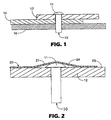
- Figure 1 portrays an exemplary substrate or structure to which adhesive films are commonly applied. Structures of this sort may occur, for example, in truck bodies, especially van and semi-trailer bodies, wherein overlapping panels 12 and 14 are aluminum side panels and member 16 is a vertical frame member inside the van body. The structure is held together by rivet 10, having head 11, which protrudes above the exterior surface of panel 12.
- film 20 comprises a backing and a pressure activated adhesive layer, wherein the adhesive layer is adjacent to surface 23 of panel 12.
- film 20 comprises a thermoplastic backing, which is durable at room temperature but soft and conformable at elevated temperatures. It has been found that commonly used thermoplastic film materials, such as plasticized polyvinyl chloride, polyolefin polymers and copolymers, and a variety of polyesters, exhibit a range of suitable temperatures above their softening points at which the method of the present invention can be used. It will be understood that some film materials having softening points at or below room temperature may be suitable for some applications of the present invention without the heating step.
- multilayer films such as those comprising an overlaminate, as well as single layer films, have been found useful in the present invention.
- Suitable adhesive films are commercially available from 3M Company, and are commonly called marking films. Examples include 3MTM ScotchcalTM Marking Film, available from 3M Company, St. Paul, MN, and thermoformable 3MTM ScotchliteTM Reflective Sheeting, also available from 3M Company. It is an advantage of the present invention that film materials which might not have been previously suitable as adhesive laminating films can now be used, due to greater latitude in heating which is made possible by the reduced mechanical contact occurring during the conforming process.
- Film 20 is applied by, for example, hand lamination, over surface 23 and rivet head 11.
- detached region 24 is formed by a detached section 21 of film 20 which is held away from panel 12 by rivet head 11, a phenomenon referred to as tenting.
- bridging occurs, wherein film 20 covers the depression without conforming to it. While film tenting and bridging may or may not have significant effects on the appearance of the laminated film, they can have a detrimental effect on the long-term durability of the film. For example, if weathering or other adverse conditions cause embrittlement or cracking of film 20, the unsupported section 21 may tear or be removed entirely, while damage to the attached portion of film 20 may be much less visible due to the fact that it is supported and held in place by surface 23.
- the present invention is useful for conforming relatively small detached sections of film to a surface
- the methods of the present invention are not so limited. It has been found that larger detached sections of film can be conformed to a surface by the method of the present invention using easily learned techniques.
- detached sections near the periphery of the detached region are first heat softened and aspirated, followed by repeated application of heat and aspiration to the remaining detached region. The volume of the detached region becomes progressively smaller, until the entire detached film section has been conformed and adhered to the surface.
- An alternative technique which has been found useful for conforming large detached sections of film is to insert the aspirator probe into the film in the detached region, without applying vacuum, then start the vacuum, and finally heat portions of the film adjacent the detached region, beginning in the areas farthest from the aspirator probe, while maintaining aspiration. In the case of film which is highly conformable at room temperature, heating may not be necessary to produce acceptable conformance.
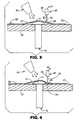
- the apparatus includes heat source 30 and aspirator probe 32.
- Heat source 30 may be, for example, a source of heated air which is blown at detached film section 21, a radiant heat source, or any other heat source capable of heating detached film section 21 to a suitable temperature without scorching, burning, or otherwise damaging the film.
- Energy for heat source 30 may be from an electrical source, from combustion of a fuel, or from any other suitable source. It is preferred that detached film section 21 be heated to a temperature above its softening point, and preferably to a temperature where most, and preferably all, residual stresses are relieved, but not so hot that the film 20 loses its integrity, becomes scorched, or is otherwise damaged.
- aspirator probe 32 comprises a contact portion 34 and a connector portion 36.
- Contact portion 34 may be, for example, a metal tube or hollow needle having end 33 squarely cut off in a plane perpendicular to the central cylindrical axis of the tube. It has been found that metal tubes having outer and inner diameters similar to 10 to 22 gauge hypodermic syringe needles are particularly suitable. Tubing of this sort is available from Aldrich Scientific, 1001 West Saint Paul Avenue, Milwaukee, WI 53233. As specified by Aldrich, hypodermic tubing of the 10 gauge size has an inside diameter of about 2.7 millimeters and an outside diameter of about 3.4 millimeters. Hypodermic tubing of the 20 gauge size has an inside diameter of about 0.58 millimeters and an outside diameter of about 0.90 millimeters.
- the optimal gauge depends on several factors, including the heat source type and temperature, film type, film thickness, the amount of detached film, and vacuum level and airflow characteristics of the vacuum source. It has been found that 15-20 gauge tubing is preferred for typical graphic marking films applied over rivets. Smaller diameter tubes tend to reduce the flow rate of the probe. Reduced flow rates can, in some cases, have a detrimental effect on the net pressure differential achievable in pressing film section 21 against rivet head 11 and surface 23. Reduced flow rates may also reduce the speed at which conformance of film section 21 against rivet head 11 and panel 12 is achieved. Larger diameter tubes, on the other hand, tend to produce larger apertures in the film 20, which may have a detrimental effect on appearance.
- tubes are not critical, though metal tubes, particularly tubes made of stainless steel hypodermic needle tubing, have the advantage of durability. It will be appreciated that while cylindrical tubing has been found suitable, other cross-sectional shapes may also be used, and may in some instances offer advantages, which would cause them to be preferred. Moreover, while cylindrical tubes of constant cross section have the advantage of simplicity, it may be useful in some instances to use tubes of varying or adjustable cross sectional dimension. For example, a short tube of small diameter which contacts the film might then expand or be replaced by a larger diameter tube for enhanced airflow and less risk of clogging. Also, different probe tip configurations may be appropriate for different applications.
- probe tips which are squarely cut in a plane perpendicular to the axis of the tube to produce a flat tip, have been found suitable for applications wherein the film is heated prior to aspiration.
- a probe with a beveled, serrated, or similar configuration that is better capable of cutting the film might be more useful. It is contemplated that assortments of probes of different configurations may be provided and that probes will be easily removed and installed, so that the user can select the most appropriate probe for any particular task and, if necessary, try a variety of probe tips before deciding on the one which is most suitable.
- aspiration of entrapped air from detached region 24 is initiated by contacting aspirator probe 32 onto detached film section 21, and continuing to urge it against the film section 21, to form indentation 40.
- this downward urging is performed after heat softening of film section 21.
- the level of heat softening and the downward force on probe 32 reach levels sufficient to produce penetration of film section 21, thereby forming aperture 50, as portrayed in Figure 5.
- this penetration is produced simply by exerting sufficient probe force against sufficiently heat softened film section 21, while in an alternative embodiment, a predetermined probe force is first exerted and maintained, prior to heat softening, and the film section 21 is then heated until sufficient softening occurs to allow penetration of the probe through the film section 21 and consequent formation of aperture 50.
- the probe tip is able to penetrate the film section 21 without heat, and the film is conformed to the surface with or without heating, as needed, depending on the properties of the film 20 being used.
- the inventors do not wish to be bound by any particular theory as to the exact mechanism of probe penetration through the heat softened film, and in fact observation of the penetration phenomenon under various conditions suggests that more than one mode of penetration may occur. In some instances, it appears that penetration may be aided by heat-softened film section being drawn into the probe by the vacuum applied to the probe. In other cases, the probe may mechanically cut at least a portion of the film section prior to penetration. Likewise, the exact nature of the seal between contact portion 34 of probe 32 and film section 21 is not known. Moreover, it is not known whether a significant amount of sealing occurs, or, if it does occur, the time duration of any such sealing.
- probe 32 is retracted, leaving aperture 50, which can, by suitable choice of the size of contact portion 34, is preferably sufficiently small to be essentially inconspicuous.
- vacuum source may include any device, including any volume or enclosure that preferably provides a reduced air pressure therein which is capable of generating a flow of air sufficient to produce an effective level of vacuum in the detached region 24 when aspirated by an aspirator probe connected to the vacuum source.
- Vacuum sources may be continuous or intermittent. Examples of continuous vacuum sources include piston type vacuum pumps, rotary vane type vacuum pumps, turbine type vacuum apparatus such as those used in vacuum cleaners, hydrodynamic flow generating devices such as venturi devices, and other continuous airflow apparatus which produce reduced air pressures while generating an effective level of airflow. Examples of intermittent vacuum sources include spring actuated or manually actuated pistons and diaphragms, elastic bulbs, as well as other devices which produce reduced pressure by an expansion of an enclosed volume. Vacuum tanks and other enclosed volumes from which a quantity or air has been removed can also function as vacuum sources. Vacuum sources can also include combinations of the above devices and apparatus.
- vacuum valve will mean any valve interposed between an aspirator probe and a vacuum source. Vacuum valves may be used to control the application of vacuum to the aspirator probe.
- aspirator probe 32 is provided as a handheld device. More particularly, probe 32 is provided as a handheld probe preferably having approximately the size, shape, and general configuration of a writing instrument such as a pencil or pen, so as to take advantage of the dexterity already developed by many people in using devices of this configuration.
- heating of the film can be provided by an electrically powered heat gun. Since heat guns of this sort are commercially available with air temperature sensing instrumentation and air temperature controlling systems, it has been found that operators can develop a high level of skill in producing an effective heating and aspirating sequence to achieve conformance of film section 21 around rivets and other surface irregularities without significant damage to the film 20.
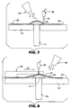
- probe 32 can be positioned and urged against detached film section 21 by use of a mechanical holding and moving means, as portrayed schematically in Figure 8.
- Probe 32 is positioned in the horizontal direction, relative to, for example, rivet head 11, by probe holder 80, represented schematically in sectional side view, which rests on film 20 and is slidable thereon to position probe 32 in the horizontal direction.
- Figure 8 portrays fixture 80 prior to positioning, being moved in a direction along the arrow designated by the numeral 81 for final positioning prior to aspiration.
- Figure 9 portrays probe 32 in position for aspirating detached film section 21 prior to contacting the film 20. It is preferred that probe holder 80 be configured so as not to contact any portion of film 20 which is in a heat softened state, as this may produce mechanical damage to the film surface. Probe holder 80 may include locating means such as notches or other features, which engage specific mechanical features of the substrate to which film 20 is being laminated, for the purpose of locating holder 80 relative to the rivet 10 or other feature to which detached film section 21 is being conformed. For example, holder 80 may comprise one or more notches which receive other rivets in areas where film 20 is unheated, so as to be positively located relative to rivet 10. Additionally, some or all of holder 80 may be made of a transparent material to enable better viewing of the area proximate to detached region 24.
- locating means such as notches or other features, which engage specific mechanical features of the substrate to which film 20 is being laminated, for the purpose of locating holder 80 relative to the rivet 10 or other feature to which detached film section 21 is being
- Heat source 30 is portrayed only schematically, and may take many forms, such as a hand held heat gun or a heating device incorporated into probe holder 80.
- the heat source may be connected with the probe as a single, handheld unit.
- the hand held unit may include a self-contained vacuum source such as a vacuum pump.
- Figure 10 portrays aspirator probe 32 in contact with detached film 21, just prior to penetration of film 21 and beginning of aspiration.
- the probe 32 is moved in the direction of the arrow 91 in order to penetrate the film.
- Vertical motion and urging of probe 32 against detached film 21 may be produced and controlled by any suitable means, not shown.
- Such urging means include manual actuation, fluid or vacuum operated actuators, mechanical linkages, electromechanical devices such as motors and solenoids, as well as springs and other resilient mechanical components.
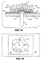
- an array 142 of aspirator probes 32 may be provided.
- array 142 may also include array 140 of heating elements 146.
- heating elements 146 are shown as separate elements, they may optionally be all part of a single heat source. For example, they could be nozzles in a single manifold carrying heated air.
- Heat source 140 may be a source of heated forced air, radiant heat, or other suitable heat source.
- probes 32 are preferably independently movable and resiliently mounted so that when array 142 is lowered onto detached film section 21, each of probes 32 contacts detached film section 21 with a suitable force, without either causing or preventing other probes from also contacting film section 21.
- one or more of probes 32 may penetrate film 21. Probes which contact the film in areas which are not detached will not penetrate, while those contacting detached areas may be expected to penetrate, as portrayed at penetration point 164.
- conformance of thermoplastic adhesive films to test plates was visually evaluated for degree of conformance, avoidance of air entrapment, absence of wrinkles, and other damage to the film, which may have occurred during the conforming process.
- a useful measure of conformance is lifting distance d, which is the distance from the point of detachment on a protrusion to the point at which the detached film section contacts the surface to which it is being adhered.
- lifting distance d is the distance from the point of detachment on a protrusion to the point at which the detached film section contacts the surface to which it is being adhered.
- complete conformance with no tenting the film is attached completely up to the edge of the protrusion (such as the edge of a rivet head), resulting in a lifting distance of 0.
- detached film section 21 is portrayed as having outer detachment boundary 171 and inner detachment boundary 173, wherein film 20 is attached to surface 23 outside of boundary 171 and attached to rivet head 11 inside of boundary 173, but detached in region 172, which is inside boundary 171 and outside of boundary 173.
- Lifting distance d is measured at several sample points, producing distances d1, d2, d3, and d4, for example. Average lifting distance D may then be reported as the average of measurements d1-d4. Since the effects of film detachment are primarily visual, the location of boundaries 171 and 173 are determined visually, and sufficiently precise measurements can usually be made with a millimeter scale.
- a typical location may be selected for taking a single measurement, d, based upon the overall visual effect of the tenting. This process, referred to as visual averaging, has been found in many cases to give a fair portrayal of the level of conformance to the film to the surface in the areas around rivets.
- Air entrapment Another defect arising from incomplete film attachment is air entrapment, which occurs as bubbled or wrinkled film at points near, but not adjacent to, protrusions. Wrinkles may be the result of air entrapment or of film deformation, which leaves an excess amount of film in a particular location. Air entrapment may not be permanent. If the amount of entrapped air is sufficiently small, the air may dissipate over time, thereby allowing film in the affected area to adhere uniformly to the substrate without the appearance of visual defects from the entrapped air.
- thermoplastic adhesive films commercially available from 3M Company, St. Paul, MN
- laminating them to painted aluminum test plates having dimensions of 10.2 X 30.4 centimeters, into which four test rivets had been inserted at a spacing of 7.7 centimeters, with the rivet nearest the end of the panel being at a distance of 3.5 centimeters from the end of the plate.
- the rivet spacing was chosen to place the rivets sufficiently far apart to avoid interaction between them during the laminating process.
- the test plates were painted with a standard white vehicle paint of the type commonly used on semi-trailers.
- the rivets were of a type commonly used in the fabrication of aluminum semi-trailer bodies, having a rivet head diameter of 12 millimeters, and a rivet head height of about 1.5 millimeters. The rivets were tightly pressed into the test panels so that the heads were seated firmly against the painted surface.
- Table 1 Descriptions of the films used in the following examples are given in Table 1.
- Table 1 the first column gives the use of each film and the type of adhesive used for that film.
- protective overlaminates are transparent films, which are laminated over graphic films, usually after imaging but before application to a surface, to provide protection for images on the graphic film.
- Graphic films are films, which are capable of receiving a graphic image by such imaging means as ink jet printing, electrostatic printing, thermal transfer printing, or other graphic imaging techniques.
- Changeable graphic films are those having a reduced level of adhesion, so as to allow them to be removed without the use of special equipment such as heat guns or other removal equipment.
- Films having ComplyTM performance are films in which the topography of the adhesive surface includes channels for the egress of air or other fluids. Adhesive surfaces having topographies of this sort are disclosed in U.S. Patent 6,197,397 B1.
- ControltacTM adhesive systems comprise adhesive layers having isolated protrusions, either tacky or non-tacky, on the adhesive surface. These protrusions limit initial adhesion so as to allow repositioning on a substrate prior to forming a pressure-activated bond.
- Adhesive systems of this type are disclosed in U.S. Patent 5,296,277 and U.S. Patent 5,362,516. Note: The films listed in this table are commercially available from 3M Company, St. Paul, MN.
- the film samples were laminated to the rivet head side of the test plates using a 3M PA-1 squeegee type applicator, available from 3M Company, taking care to avoid wrinkling, but allowing smooth tenting of film 20 to occur over rivet head 11, to form detached film portion 21.
- a typical distance d for the tented film was in the range of 8-10 millimeters after this initial application.
- Heating of laminated film samples was performed using a heavy-duty heat gun, available from McMaster-Carr, Atlanta, GA, and designated as McMaster-Carr catalog number 3433K21. Unless otherwise noted, an air temperature setting of 427° C (800° F) was used. Samples were placed on a laboratory workbench during heating and aspiration. The detached film section around each rivet was heated with the heat gun, using a predetermined air temperature setting, holding the heat gun at a distance of approximately 2-7 centimeters from the film surface, for about 0.5-4.0 seconds, or until softening of the film became visible. It was found that different types of films and different thicknesses of films required different amounts of heating, but that skill in judging a sufficient amount of heating could easily be learned.
- the aspirator probe which was connected to a vacuum pump, was applied to each of the tented regions at a location near the edge of the rivet head, while simultaneously removing the heat gun. After the aspirator probe had penetrated the film and conformance had been achieved, the probe was removed. Conformance of the detached film sections against the test panel was typically so rapid that a snapping sound was generated as the film became adhered to the test panel surface. The heating and aspiration process was then repeated for the remaining three rivets on each test panel. The riveted areas were then conditioned at 66°C (150°F) for 7 days. Each rivet on each sample was then tested for quality of conformance, as measured by detached film distance d, and absence of damage or other defects.
- Comparative examples were prepared using the 3M multipin punch, MPP-1 in combination with either the 3M rivet brush applicator, RBA-3, or the 3M rivet finishing pad, CMP-1.
- MPP-1 3M multipin punch
- RBA-3 3M rivet brush applicator
- CMP-1 3M rivet finishing pad
- Results for Examples 1-27 are shown in Table 2 and results for Comparative Examples C1-C16 are shown in Table 3.
- the average lifting distance, d, and the ranges of visible whole sizes for each test panel are reported.
- Descriptions of the film materials used in the examples reported in Tables 2 and 3 are given in Table 1.
- the tubing used was stainless steel hypodermic tubing obtained from Aldrich Scientific.
- the visible hole size in column 6 refers to the apertures produced by the aspirator probes, while in Table 3, the visible hole size refers to holes produced by the 3M MPP-1 multipin punch used prior to heating the detached sections or holes created when pressing the detached sections down with the RBA-3 brush or the CMP-1 rivet finishing pad.
- Examples 1-9 demonstrate the that lifting distances d of less than 2.0 mm can be achieved with a changeable adhesive, as is used on 3MTM ScotchcalTM 3500C Marking Film. Moreover, as demonstrated by Examples 4-6 and Examples 7-9, lifting distances of less than 2.0 mm can, with suitable choice of probe diameter, also be achieved when an overlaminate is present. Historically, it has been noted that good conformance, as measured by lifting distance d, has been more difficult to achieve when changeable adhesives are used, due to the lower adhesion of such adhesives. Likewise, it has been found that films having an overlaminate are more difficult to conform to irregular surfaces, due to their increased thickness, which results in increased stiffness.
- Comparative examples C1 and C2 demonstrate that, even without an overlaminate, the use of a brush to conform 3MTM ScotchcalTM 3500C Marking Film to a rivet head does not achieve a lifting distance in the range of 2.0 mm, while the use of pad or brush for this purpose produces significant surface damage and wrinkling. Comparative Examples C3-C6 further demonstrate that when overlaminates are present, lifting distances in the range of 2.0 mm are not achieved using the brush or the pad, and that significant surface damage and wrinkling can occur.
- Examples 10-12 demonstrate the method of the present invention in conforming 3MTM ScotchcalTM 3540C Marking Film to rivet heads.
- the adhesive layer of 3540C Marking Film has a surface topography of the type disclosed in U.S. Patent 6,197,397, to allow egress of trapped air.
- probe diameters can be chosen to achieve lifting distances d of less than 2.0 mm with relatively little surface damage.
- Examples 13-16 demonstrate that with suitable choice of probe diameter, the present invention can be used to achieve lifting distances of 1.0 mm or less with a thinner vinyl backing, namely one having a thickness of 0.05 mm (2 mils), even with 3MTM ScotchcalTM 180-10 Marking Film, wherein the adhesive layer does not have a surface topography incorporating air egress channels. It was noted that when using 180-10 film, there was a noticeable amount of trapped air in the areas around each rivet, and it was speculated that this was due to the absence of air egress channels in the adhesive layer. Referring to Table 3, Comparative Examples C9 and C10, using 3MTM ScotchcalTM 180-10 Marking Film, show somewhat greater lifting distances d than those produced by the present invention in examples 13-16.
- Examples 17-20 illustrate that when air egress channels are added to the adhesive layer, as is done in 3MTM ScotchcalTM 180-10C Marking Film, the amount of trapped air is reduced, and, with suitable choice of probe diameter, lifting distance d can be reduced to below 1.0 mm. Comparative examples C11 and C12 show comparable to somewhat larger lifting distances for this film, with a type of wrinkling not seen in samples produced in Examples 17-20.
- Examples 21-24 demonstrate the use of a backing having a thickness of 0.05 mm (2 mils) with a vinyl overlaminate having a backing thickness of 0.05 mm (2 mils), resulting in a film having a total backing thickness of approximately 0.1 mm (4 mils).
- a lifting distance d of 0.5 mm can be achieved, whereas, as shown in Table 3, Comparative Examples C 13 and C 14, both the brush and pad were unable to achieve lifting distances below 2.0 mm.
- Example 24 which produced the lowest value of d also did not produce any noticeable film damage.
- Examples 25-29 demonstrate that a variety of different types of tubing can be used as aspirator probes, and that the tubes need not be circular in cross section, nor do they need to be made of metal.
- a heat gun setting of 260°C (500° F) was used in these examples.
- a non-circular probe was made by flattening a 13 gauge stainless steel hypodermic syringe needle with a pliers to form an oblong cross section at the end of the tube. This flattened tube was then successfully used to aspirate detached film regions near several rivets.
- a 13 gauge syringe needle with a sharp beveled tip of the type used in hypodermic medical applications was used to aspirate several detached regions near rivet heads. While the aspiration and conformance of the film to the area around the rivet head was successful, the needle tended to scratch the film if not used with extreme care. It was also found that because of the beveled tip and the resulting elongated aperture at the end of the probe, the probe had to be inserted a greater distance into the detached region to achieve aspiration.
- a nonmetallic probe in the form of a glass eyedropper tube having an inside diameter of about 1.5 mm and an outside diameter of about 2.5 mm was connected to a vacuum source via a vacuum line and used successfully to aspirate detached regions around several rivet heads.
- a nonmetallic probe in the form of a plastic tube from a laboratory squirt bottle having an inside diameter of about 0.8 mm was successfully used to aspirate detached regions around several rivet heads.
- the plastic tube showed a tendency to clog after several aspirations, and also suffered heat damage, which may have contributed to the clogging.
- a nonmetallic probe in the form of a length of flexible vacuum hose, was used to aspirate detached regions around several rivet heads. While the detached regions were successfully aspirated, there was a tendency for portions of the film to be sucked into the hose, and holes in the film having a diameter on the order of 3 mm were sometimes produced.
- Examples 30 and 31 demonstrate that the order in which the steps of heating, probe insertion, and application of vacuum are performed can have a significant effect on the level of conformance achieved.
- a 13 gauge square tipped stainless steel tube was inserted into a detached region of laminated film prior to application of heat or vacuum.
- the probe was connected, via a flexible vacuum hose, to a closed vacuum valve, which was in turn connected to a vacuum source.
- the detached region of the film was then heat softened, after which the vacuum valve was opened, so as to apply vacuum to the detached region. Good conformance was achieved.
- a detached section of laminated film was first heat softened using a heat gun, after which a 13 gauge square tipped stainless steel needle, connected, via a flexible vacuum hose, to a closed vacuum valve, which was in turn connected to a vacuum source, was inserted into the detached region. The vacuum valve was then opened and the detached region aspirated. Limited conformance was achieved, due, at least in part, to the difficulty of achieving an adequate flow restriction or seal between the probe and the film. It was speculated that insertion of the probe into heated film, without the simultaneous application of vacuum, may have had a detrimental effect on the flow restriction or seal that could be achieved.
- a detached section over a rivet was heated with the heat gun used in Examples 1-24, but using a heat setting of 399° C (750° F) for a time of 1-3 seconds.
- a flat tipped 13 gauge needle attached via a vacuum hose to a vacuum pump was placed against the detached film section near a rivet edge and urged against the rivet base.
- the reflective sheeting rapidly collapsed around the rivet head to produce good conformance.
- Test panels were prepared as in Examples 7-9, using 3MTMScotchcalTM 3500C Marking Film with 3MTMScotchcalTM 8910 vinyl overlaminate laminated thereon.
- a shell and tip of a Pentel 0.5 mm P215 mechanical pencil was used as an aspirator probe.
- the shell and tip were connected to a vacuum hose which was in turn connected to a to a vacuum pump. Removal of detached regions and conformance around rivet heads proceeded rapidly, and the probe was found easy to maneuver around rivets, due to its familiar shape.
- the average value for lifting distance d after aging of the conformed film for 18 hours at room temperature was 0.7 mm, and the average size of the hole left in the film after aspiration was 0.8 mm. No film damage was observed.
- Two test panels were prepared as in Examples 7-9, using 3MTM ScotchcalTM 3500C Marking Film with 3MTMScotchcalTM 8910 vinyl overlaminate laminated thereon.
- a "goot” TM TP-100 desoldering gun produced by Taiyo Electric Ind. Co. Ltd., Japan, and commercially available from Radio Shack Retail Stores, was used as the aspirator device.
- a flat tipped, 18 gauge stainless steel tube having a length of 1 centimeter was attached to the end of the desoldering gun and used as the aspirator probe.
- the TP-100 desoldering gun contains a vacuum source in the form a diaphragm.
- a 4 centimeter by 12 centimeter sheet of 3MTMScotchcalTM 180-10 Marking Film was applied to a flat, painted, aluminum sheet in a manner which left detached regions having areas in the range of 4-100 square millimeters trapped between the film and the painted sheet.
- Each detached film section was heated using a heat gun setting of 399° C (750° F).
- the detached regions were aspirated with a flat tipped 18 gauge aspirator probe connected to a vacuum pump. At each detached region, the aspirator probe formed an aperture in the film, the trapped air was quickly aspirated away, and the film conformed to the surface.
- the only visible indication of the aspiration was the presence of small marks having diameters of about 0.1-1.0 mm in diameter, corresponding to the points of contact of the needle with the film.
- a test panel was prepared by laminating a 4 centimeter x 12 centimeter sheet of 3MTM ScotchcalTM 3500C Marking Film onto an aluminum sheet having 3 circular indentations such that the film bridged the indentations.
- Each indentation was about 6 mm deep and about 28 mm in diameter.
- the film section bridging each of the indentations was heated using a heat gun air temperature setting of 399° C (750° F) and aspirated with an 18 gauge stainless steel probe connected to a vacuum source by slowly moving the probe into contact with the detached section. As each detached region was aspirated, the probe was moved toward the indentation to follow the film section as it conformed to the indentation, so as to maintain communication between the detached region and the probe. In each case, the film section was successfully conformed to the indentation.
Landscapes
- Engineering & Computer Science (AREA)
- Manufacturing & Machinery (AREA)
- Mechanical Engineering (AREA)
- Lining Or Joining Of Plastics Or The Like (AREA)
- Mechanical Treatment Of Semiconductor (AREA)
- Application Of Or Painting With Fluid Materials (AREA)
- Magnetic Heads (AREA)
- Adhesive Tapes (AREA)
- Adhesives Or Adhesive Processes (AREA)
Claims (10)
- Verfahren zum Aufbringen einer Folie auf ein Substrat, das aufweist:Bereitstellen einer Folie, die eine Klebeschicht aufweist;Anordnen der Folie auf ein Substrat, so dass ein Abschnitt der Klebeschicht mit dem Substrat in Kontakt steht;Auswählen eines Bereichs zwischen der Folie und dem Substrat, in dem die Klebeschicht nicht mit dem Substrat in Kontakt steht;Bereitstellen einer Öffnung in der Folie, die benachbart zu dem ausgewählten Bereich liegt; undAnwenden eines Vakuums auf den ausgewählten Bereich durch die Öffnung, um Luft aus dem Bereich abzusaugen und die Folie, die benachbart zu dem ausgewählten Bereich liegt, zu dem Substrat zu drängen.
- Verfahren zum Anpassen einer Klebefolie an ein Substrat nach Anspruch 1, wobei das Anwenden des Vakuums auf den ausgewählten Bereich das Bewegen mindestens einer Absaugsonde mindestens teilweise in den Bereich aufweist.
- Verfahren zum Anpassen einer Klebefolie an ein Substrat nach Anspruch 2, wobei das Bereitstellen einer Öffnung in der Folie durch das Drängen mindestens einer der Sonden gegen die Folie ausgeführt wird, bis die Folie durchstoßen ist.
- Verfahren zum Aufbringen einer Folie auf ein Substrat nach Anspruch 1, wobei die Öffnung in der Folie in einem Abschnitt der Folie bereitgestellt wird, der von dem Substrat abgetrennt ist.
- Verfahren zum Aufbringen einer Folie auf ein Substrat nach Anspruch 1, das das Aufweichen der Folie, die benachbart zu dem ausgewählten Bereich liegt, vor dem Anwenden des Vakuums auf den ausgewählten Bereich aufweist.
- Verfahren zum Aufbringen einer Folie auf ein Substrat nach Anspruch 1, wobei das Bereitstellen einer Öffnung in der Folie durch das Drängen mindestens einer Sonde gegen einen Abschnitt der Folie ausgeführt wird, der benachbart zu dem ausgewählten Bereich liegt.
- Verfahren zum Aufbringen einer Folie auf ein Substrat nach Anspruch 6, wobei das Anwenden eines Vakuums auf den ausgewählten Bereich durch das Anwenden eines Vakuums auf einen Kanal in mindestens einer der Sonden ausgeführt wird.
- Verfahren zum Aufbringen einer Folie auf ein Substrat nach Anspruch 6, das das Leiten von Hitze zu einem Abschnitt der Folie aufweist, der benachbart zu dem ausgewählten Bereich liegt.
- Verfahren zum Aufbringen einer Folie auf ein Substrat nach Anspruch 1, wobei die Klebeschicht Kanäle zum Austritt von Luft oder anderen Fluiden aufweist.
- Verfahren zum Aufbringen einer Folie auf ein Substrat nach Anspruch 1, wobei die Folie des weiteren ein grafisches Bild aufweist, das darauf aufgebracht ist.
Applications Claiming Priority (3)
| Application Number | Priority Date | Filing Date | Title |
|---|---|---|---|
| US34657202P | 2002-01-08 | 2002-01-08 | |
| US346572P | 2002-01-08 | ||
| PCT/US2002/040894 WO2003059602A1 (en) | 2002-01-08 | 2002-12-19 | Method of conforming a film to a surface |
Publications (2)
| Publication Number | Publication Date |
|---|---|
| EP1463623A1 EP1463623A1 (de) | 2004-10-06 |
| EP1463623B1 true EP1463623B1 (de) | 2005-06-08 |
Family
ID=23360040
Family Applications (1)
| Application Number | Title | Priority Date | Filing Date |
|---|---|---|---|
| EP02806484A Expired - Lifetime EP1463623B1 (de) | 2002-01-08 | 2002-12-19 | Verfahren zum anpassen einer folie an eine fläche |
Country Status (10)
| Country | Link |
|---|---|
| US (1) | US7141133B2 (de) |
| EP (1) | EP1463623B1 (de) |
| JP (1) | JP4537069B2 (de) |
| KR (1) | KR100971048B1 (de) |
| CN (1) | CN100360303C (de) |
| AT (1) | ATE297310T1 (de) |
| AU (1) | AU2002367021A1 (de) |
| CA (1) | CA2471767A1 (de) |
| DE (1) | DE60204599T2 (de) |
| WO (1) | WO2003059602A1 (de) |
Families Citing this family (20)
| Publication number | Priority date | Publication date | Assignee | Title |
|---|---|---|---|---|
| US7709070B2 (en) | 2001-12-20 | 2010-05-04 | The Procter & Gamble Company | Articles and methods for applying color on surfaces |
| US7316832B2 (en) | 2001-12-20 | 2008-01-08 | The Procter & Gamble Company | Articles and methods for applying color on surfaces |
| US6872268B2 (en) * | 2002-06-11 | 2005-03-29 | 3M Innovative Properties Company | Method of conforming an adherent film to a substrate by application of vacuum |
| WO2004074008A2 (en) | 2003-02-14 | 2004-09-02 | Avery Dennison Corporation | Multi-layer dry paint decorative laminate having discoloration prevention barrier |
| US20040161564A1 (en) | 2003-02-14 | 2004-08-19 | Truog Keith L. | Dry paint transfer laminate |
| US20050196607A1 (en) | 2003-06-09 | 2005-09-08 | Shih Frank Y. | Multi-layer dry paint decorative laminate having discoloration prevention barrier |
| US20040247837A1 (en) * | 2003-06-09 | 2004-12-09 | Howard Enlow | Multilayer film |
| JP4726502B2 (ja) * | 2005-01-24 | 2011-07-20 | 西山ステンレスケミカル株式会社 | Fpd用ガラス基板の製造方法 |
| WO2007090830A1 (en) * | 2006-02-07 | 2007-08-16 | Inergy Automotive Systems Research (Société Anonyme) | Process for manufacturing a fuel tank |
| WO2008079124A1 (en) * | 2006-12-26 | 2008-07-03 | Thomson Licensing | Intermediate film identifier marking |
| US20090308540A1 (en) * | 2008-06-12 | 2009-12-17 | Puckett Jr Lowell E | Handheld Accessory Tool and Method for the Application of Adhesive Films |
| JP2012530621A (ja) * | 2009-06-19 | 2012-12-06 | シモン ラーブ | ミクストメディア美術作品および制作方法 |
| US20140278277A1 (en) | 2013-03-15 | 2014-09-18 | Premier Protection Holdings, LLC | Protective film for automotive surfaces |
| US10315399B2 (en) | 2013-12-31 | 2019-06-11 | Entrotech, Inc. | Methods for application of polymeric film and related assemblies |
| JP6495641B2 (ja) * | 2014-12-12 | 2019-04-03 | アーキヤマデ株式会社 | 防水構造、及び、防水構造の脱気方法 |
| PL3302932T3 (pl) * | 2015-06-05 | 2020-07-27 | Ppg Coatings Europe B.V. | Układ i sposób laminowania dużych powierzchni |
| US10994876B2 (en) * | 2017-06-30 | 2021-05-04 | Divergent Technologies, Inc. | Automated wrapping of components in transport structures |
| CN110576593B (zh) * | 2018-08-01 | 2021-07-06 | 蓝思科技(长沙)有限公司 | 贴膜方法及其用途与玻璃面板 |
| CN110212225B (zh) * | 2019-05-31 | 2023-04-07 | 苏州擎动动力科技有限公司 | 一种直接涂布法制备膜电极的方法及其制备得到的膜电极 |
| US11173696B2 (en) * | 2019-08-01 | 2021-11-16 | B/E Aerospace, Inc. | Conduction heating for HVA lamination process |
Family Cites Families (42)
| Publication number | Priority date | Publication date | Assignee | Title |
|---|---|---|---|---|
| US326160A (en) * | 1885-09-15 | Tool for piercing holes in soles of boots or shoes | ||
| US1433971A (en) * | 1920-09-13 | 1922-10-31 | Roberts Fred Thomas | Method of and apparatus for preventing air bubbles in laminated rubber articles |
| US1672093A (en) * | 1928-01-31 | 1928-06-05 | Helena S Sadtler | Art of decorating the surfaces of various objects |
| US1895045A (en) * | 1931-07-17 | 1933-01-24 | James L Moore | Method and means for marking surfaces |
| DE807073C (de) * | 1949-07-21 | 1951-06-25 | Hans Dohse | Verfahren zum vakuumdichten Verpacken fester Verbrauchsgueter |
| US2983305A (en) * | 1959-01-12 | 1961-05-09 | Nat Plastic Products Co | Bonding panels to base surfaces |
| US3853669A (en) * | 1972-08-28 | 1974-12-10 | P Werstlein | Welding tip for plastic welding gun |
| US3861988A (en) * | 1973-01-22 | 1975-01-21 | Samuel L Preisler | Pressure sensitive rolled sheeting applicator and dispenser |
| DK143357A (de) * | 1973-09-14 | 1900-01-01 | ||
| NL7501383A (nl) | 1975-02-05 | 1976-08-09 | Jan Roelof Bisschop Ruben Kryn | Werkwijze en inrichting voor het bevestigen van een vel op een onderlaag. |
| US4261783A (en) * | 1977-01-26 | 1981-04-14 | Monarch Marking Systems, Inc. | Label printing and applying apparatus |
| JPS6026156B2 (ja) * | 1977-03-14 | 1985-06-21 | 日本バルカ−工業株式会社 | 接着方法 |
| US4204904A (en) * | 1977-10-17 | 1980-05-27 | Tabor Donald R | Roofing material handling and sealing machine |
| DE2927677C2 (de) * | 1979-07-09 | 1981-02-26 | Bonumwerke Tigges & Winckel Gmbh & Co Kg, 5620 Velbert | Gerät zum Perforieren von zur Ablösung bestimmten Tapeten |
| DE2935631A1 (de) * | 1979-09-04 | 1981-04-16 | Plate Bonn Gmbh, 5300 Bonn | Mehrschicht-kunststoff-folie, verfahren zu ihrer herstellung und deren verwendung |
| US4326909A (en) * | 1980-06-30 | 1982-04-27 | Minnesota Diversified Products, Inc. | Method and apparatus for forming a permeable insulation board for building construction |
| JPS5837071A (ja) * | 1981-07-31 | 1983-03-04 | Hiroshi Kusama | 粘着性薄膜の貼付け方法およびその装置 |
| DE3519064A1 (de) * | 1985-05-28 | 1986-12-04 | Avery International Corp., Wilmington, Del. | Mehrschichtige, selbstklebende und tiefziehbare schutzfolie insbesondere fuer kraftfahrzeuge |
| US4867816A (en) * | 1986-06-06 | 1989-09-19 | Suiter James R | Bowling lane refinishing method |
| US4944514A (en) * | 1986-06-06 | 1990-07-31 | Suitco Surface, Inc. | Floor finishing material and method |
| JPS6359517A (ja) | 1986-08-29 | 1988-03-15 | Nec Corp | 印刷配線板の製造方法 |
| JPH01123723A (ja) | 1987-11-09 | 1989-05-16 | Hitachi Ltd | プリント基板のラミネート方法 |
| US4812541A (en) | 1987-12-23 | 1989-03-14 | Avery International Corporation | High performance pressure-sensitive adhesive polymers |
| FR2643487B1 (fr) | 1989-02-17 | 1991-05-03 | Medias Actuels | Appareil de depose et pose d'affiches predecoupees en bandes sur des panneaux publicitaires |
| JPH02261874A (ja) * | 1989-03-31 | 1990-10-24 | Nippon Valqua Ind Ltd | 接着方法 |
| US5225260A (en) | 1991-03-28 | 1993-07-06 | Brady Coated Products Co. | Subsurface printable laminate with carrier and application tape |
| JPH0516600A (ja) | 1991-06-26 | 1993-01-26 | Sekisui Chem Co Ltd | 粘着シートの圧着治具および貼付方法 |
| US5246757A (en) * | 1992-04-28 | 1993-09-21 | Minnesota Mining And Manufacturing Company | Architectural signs with raised graphics |
| US5296277A (en) * | 1992-06-26 | 1994-03-22 | Minnesota Mining And Manufacturing Company | Positionable and repositionable adhesive articles |
| JPH08267398A (ja) * | 1995-04-03 | 1996-10-15 | Sekisui Chem Co Ltd | 脱気ロールおよび脱気ロールによる粘着フィルムの製造方法 |
| JP3549308B2 (ja) * | 1995-10-12 | 2004-08-04 | しげる工業株式会社 | シート状物品の接着方法 |
| DE19603344C2 (de) | 1996-01-31 | 1998-10-15 | Volker Lins | Vorrichtung zum Aufbringen einer von einem Wickel abzuziehenden selbstklebenden Schutzfolie gegen Graffiti auf eine Wand |
| EP0883658B1 (de) | 1996-02-26 | 2000-11-15 | Minnesota Mining And Manufacturing Company | Haftklebemittel enthaltender graphischer Markierungsfilm |
| US6197397B1 (en) * | 1996-12-31 | 2001-03-06 | 3M Innovative Properties Company | Adhesives having a microreplicated topography and methods of making and using same |
| JPH10199906A (ja) * | 1997-01-14 | 1998-07-31 | Sony Corp | モールド樹脂被覆電子部品の開口方法 |
| DE19733935C2 (de) | 1997-08-06 | 1999-07-22 | Volker Lins | System zum Aufbringen einer von einem Wickel abzuziehenden selbstklebenden Folie auf die Wand eines Körpers und Aufbringvorrichtung für ein solches System |
| US6649128B1 (en) * | 1998-09-23 | 2003-11-18 | Randox Laboratories Ltd | Assay device processing instrument |
| EP1148998B1 (de) | 1999-01-25 | 2003-07-16 | 3M Innovative Properties Company | Vakuumunterstütztes laminiergerät und verfahren zu dessen verwendung |
| BR0007687A (pt) * | 1999-01-25 | 2002-01-29 | 3M Innovative Properties Co | Processo de adesão de um filme revestido por adesivo a um substrato possuindo uma superfìcie, artigo para amolecer um filme e aderir o filme em uma superfìcie de um substrato, processo para economizar trabalho de aderência de um filme revestido de adesivo a um substrato possuindo uma superfìcie, e, kit para a aplicação de filmes a um substrato |
| US6311399B1 (en) * | 1999-10-05 | 2001-11-06 | 3M Innovative Properties Company | Multi-pin air release tool and method |
| US7413626B2 (en) * | 2001-01-12 | 2008-08-19 | 3M Innovative Properties Company | Adhesive film removal method and apparatus |
| US6520234B1 (en) * | 2000-05-23 | 2003-02-18 | 3M Innovative Properties Company | Steered vacuum-assisted laminating apparatus and methods of use |
-
2002
- 2002-12-19 DE DE60204599T patent/DE60204599T2/de not_active Expired - Lifetime
- 2002-12-19 CN CNB028269063A patent/CN100360303C/zh not_active Expired - Fee Related
- 2002-12-19 CA CA002471767A patent/CA2471767A1/en not_active Abandoned
- 2002-12-19 AU AU2002367021A patent/AU2002367021A1/en not_active Abandoned
- 2002-12-19 JP JP2003559748A patent/JP4537069B2/ja not_active Expired - Fee Related
- 2002-12-19 AT AT02806484T patent/ATE297310T1/de not_active IP Right Cessation
- 2002-12-19 KR KR1020047010628A patent/KR100971048B1/ko not_active IP Right Cessation
- 2002-12-19 US US10/325,509 patent/US7141133B2/en not_active Expired - Lifetime
- 2002-12-19 EP EP02806484A patent/EP1463623B1/de not_active Expired - Lifetime
- 2002-12-19 WO PCT/US2002/040894 patent/WO2003059602A1/en active IP Right Grant
Also Published As
| Publication number | Publication date |
|---|---|
| EP1463623A1 (de) | 2004-10-06 |
| ATE297310T1 (de) | 2005-06-15 |
| KR20040073554A (ko) | 2004-08-19 |
| CA2471767A1 (en) | 2003-07-24 |
| WO2003059602A1 (en) | 2003-07-24 |
| JP2005527651A (ja) | 2005-09-15 |
| US20030150547A1 (en) | 2003-08-14 |
| CN100360303C (zh) | 2008-01-09 |
| AU2002367021A1 (en) | 2003-07-30 |
| CN1612799A (zh) | 2005-05-04 |
| US7141133B2 (en) | 2006-11-28 |
| DE60204599D1 (de) | 2005-07-14 |
| JP4537069B2 (ja) | 2010-09-01 |
| DE60204599T2 (de) | 2006-01-19 |
| KR100971048B1 (ko) | 2010-07-16 |
Similar Documents
| Publication | Publication Date | Title |
|---|---|---|
| EP1463623B1 (de) | Verfahren zum anpassen einer folie an eine fläche | |
| EP1147019B1 (de) | Verfahren zum auftragen eines mit klebemittel beschichteten films | |
| US6872268B2 (en) | Method of conforming an adherent film to a substrate by application of vacuum | |
| EP2444212A1 (de) | Verfahren und vorrichtung zum schneiden eines folienmaterials | |
| JP2003145660A (ja) | 剥離ライナーおよびその製造方法 | |
| WO2014034502A1 (ja) | 保護用粘着シートの貼付け装置 | |
| KR100534973B1 (ko) | 자동차의 도막 부착성 시험 방법 및 장치 | |
| US9855732B2 (en) | Method of applying adhesive coated film | |
| JP2002011452A (ja) | マーキング用粘着シートの剥離方法及び剥離装置 | |
| CN117554184B (zh) | 一种基于手机玻璃用pe保护膜的质量检测装置 | |
| JPH03267171A (ja) | 塗膜保護方法 | |
| CN210553536U (zh) | 高温承载膜的离型膜撕除设备 | |
| JP4086215B2 (ja) | 車体の修理方法及び修理作業量算出方法 | |
| CN117388166A (zh) | 一种滚球法初粘性测试设备及测试方法 | |
| JP2006001068A (ja) | 装飾フィルムの貼り付け方法及び装飾フィルムの貼り付け装置 | |
| JP2681280B2 (ja) | ラベル類の貼着時における仮支持シート | |
| KR20230118876A (ko) | 접착 필름 적용 방법 | |
| US20090191372A1 (en) | Method and apparatus for applying graphic designs to vehicles | |
| CN116067723A (zh) | 快速检测漆膜的色差与厚度的方法 | |
| JPH1110997A (ja) | 物品の表面への印刷面作製方法 |
Legal Events
| Date | Code | Title | Description |
|---|---|---|---|
| PUAI | Public reference made under article 153(3) epc to a published international application that has entered the european phase |
Free format text: ORIGINAL CODE: 0009012 |
|
| 17P | Request for examination filed |
Effective date: 20040728 |
|
| AK | Designated contracting states |
Kind code of ref document: A1 Designated state(s): AT BE BG CH CY CZ DE DK EE ES FI FR GB GR IE IT LI LU MC NL PT SE SI SK TR |
|
| AX | Request for extension of the european patent |
Extension state: AL LT LV MK RO |
|
| GRAP | Despatch of communication of intention to grant a patent |
Free format text: ORIGINAL CODE: EPIDOSNIGR1 |
|
| GRAS | Grant fee paid |
Free format text: ORIGINAL CODE: EPIDOSNIGR3 |
|
| GRAA | (expected) grant |
Free format text: ORIGINAL CODE: 0009210 |
|
| AK | Designated contracting states |
Kind code of ref document: B1 Designated state(s): AT BE BG CH CY CZ DE DK EE ES FI FR GB GR IE IT LI LU MC NL PT SE SI SK TR |
|
| PG25 | Lapsed in a contracting state [announced via postgrant information from national office to epo] |
Ref country code: FI Free format text: LAPSE BECAUSE OF FAILURE TO SUBMIT A TRANSLATION OF THE DESCRIPTION OR TO PAY THE FEE WITHIN THE PRESCRIBED TIME-LIMIT Effective date: 20050608 Ref country code: AT Free format text: LAPSE BECAUSE OF FAILURE TO SUBMIT A TRANSLATION OF THE DESCRIPTION OR TO PAY THE FEE WITHIN THE PRESCRIBED TIME-LIMIT Effective date: 20050608 Ref country code: CZ Free format text: LAPSE BECAUSE OF FAILURE TO SUBMIT A TRANSLATION OF THE DESCRIPTION OR TO PAY THE FEE WITHIN THE PRESCRIBED TIME-LIMIT Effective date: 20050608 Ref country code: SK Free format text: LAPSE BECAUSE OF FAILURE TO SUBMIT A TRANSLATION OF THE DESCRIPTION OR TO PAY THE FEE WITHIN THE PRESCRIBED TIME-LIMIT Effective date: 20050608 Ref country code: SI Free format text: LAPSE BECAUSE OF FAILURE TO SUBMIT A TRANSLATION OF THE DESCRIPTION OR TO PAY THE FEE WITHIN THE PRESCRIBED TIME-LIMIT Effective date: 20050608 Ref country code: BE Free format text: LAPSE BECAUSE OF FAILURE TO SUBMIT A TRANSLATION OF THE DESCRIPTION OR TO PAY THE FEE WITHIN THE PRESCRIBED TIME-LIMIT Effective date: 20050608 Ref country code: EE Free format text: LAPSE BECAUSE OF FAILURE TO SUBMIT A TRANSLATION OF THE DESCRIPTION OR TO PAY THE FEE WITHIN THE PRESCRIBED TIME-LIMIT Effective date: 20050608 Ref country code: TR Free format text: LAPSE BECAUSE OF FAILURE TO SUBMIT A TRANSLATION OF THE DESCRIPTION OR TO PAY THE FEE WITHIN THE PRESCRIBED TIME-LIMIT Effective date: 20050608 Ref country code: ES Free format text: LAPSE BECAUSE OF FAILURE TO SUBMIT A TRANSLATION OF THE DESCRIPTION OR TO PAY THE FEE WITHIN THE PRESCRIBED TIME-LIMIT Effective date: 20050608 |
|
| REG | Reference to a national code |
Ref country code: GB Ref legal event code: FG4D |
|
| REG | Reference to a national code |
Ref country code: CH Ref legal event code: EP |
|
| REF | Corresponds to: |
Ref document number: 60204599 Country of ref document: DE Date of ref document: 20050714 Kind code of ref document: P |
|
| REG | Reference to a national code |
Ref country code: IE Ref legal event code: FG4D |
|
| PG25 | Lapsed in a contracting state [announced via postgrant information from national office to epo] |
Ref country code: DK Free format text: LAPSE BECAUSE OF FAILURE TO SUBMIT A TRANSLATION OF THE DESCRIPTION OR TO PAY THE FEE WITHIN THE PRESCRIBED TIME-LIMIT Effective date: 20050908 Ref country code: SE Free format text: LAPSE BECAUSE OF FAILURE TO SUBMIT A TRANSLATION OF THE DESCRIPTION OR TO PAY THE FEE WITHIN THE PRESCRIBED TIME-LIMIT Effective date: 20050908 Ref country code: BG Free format text: LAPSE BECAUSE OF FAILURE TO SUBMIT A TRANSLATION OF THE DESCRIPTION OR TO PAY THE FEE WITHIN THE PRESCRIBED TIME-LIMIT Effective date: 20050908 Ref country code: GR Free format text: LAPSE BECAUSE OF FAILURE TO SUBMIT A TRANSLATION OF THE DESCRIPTION OR TO PAY THE FEE WITHIN THE PRESCRIBED TIME-LIMIT Effective date: 20050908 |
|
| PG25 | Lapsed in a contracting state [announced via postgrant information from national office to epo] |
Ref country code: PT Free format text: LAPSE BECAUSE OF FAILURE TO SUBMIT A TRANSLATION OF THE DESCRIPTION OR TO PAY THE FEE WITHIN THE PRESCRIBED TIME-LIMIT Effective date: 20051114 |
|
| PG25 | Lapsed in a contracting state [announced via postgrant information from national office to epo] |
Ref country code: CY Free format text: LAPSE BECAUSE OF FAILURE TO SUBMIT A TRANSLATION OF THE DESCRIPTION OR TO PAY THE FEE WITHIN THE PRESCRIBED TIME-LIMIT Effective date: 20051219 Ref country code: IE Free format text: LAPSE BECAUSE OF NON-PAYMENT OF DUE FEES Effective date: 20051219 |
|
| PG25 | Lapsed in a contracting state [announced via postgrant information from national office to epo] |
Ref country code: LU Free format text: LAPSE BECAUSE OF NON-PAYMENT OF DUE FEES Effective date: 20051231 Ref country code: MC Free format text: LAPSE BECAUSE OF NON-PAYMENT OF DUE FEES Effective date: 20051231 |
|
| ET | Fr: translation filed | ||
| PLBE | No opposition filed within time limit |
Free format text: ORIGINAL CODE: 0009261 |
|
| STAA | Information on the status of an ep patent application or granted ep patent |
Free format text: STATUS: NO OPPOSITION FILED WITHIN TIME LIMIT |
|
| 26N | No opposition filed |
Effective date: 20060309 |
|
| REG | Reference to a national code |
Ref country code: IE Ref legal event code: MM4A |
|
| PGFP | Annual fee paid to national office [announced via postgrant information from national office to epo] |
Ref country code: FR Payment date: 20061220 Year of fee payment: 5 |
|
| PGFP | Annual fee paid to national office [announced via postgrant information from national office to epo] |
Ref country code: CH Payment date: 20061227 Year of fee payment: 5 |
|
| REG | Reference to a national code |
Ref country code: CH Ref legal event code: PL |
|
| PG25 | Lapsed in a contracting state [announced via postgrant information from national office to epo] |
Ref country code: LI Free format text: LAPSE BECAUSE OF NON-PAYMENT OF DUE FEES Effective date: 20071231 Ref country code: CH Free format text: LAPSE BECAUSE OF NON-PAYMENT OF DUE FEES Effective date: 20071231 |
|
| REG | Reference to a national code |
Ref country code: FR Ref legal event code: ST Effective date: 20081020 |
|
| PGFP | Annual fee paid to national office [announced via postgrant information from national office to epo] |
Ref country code: NL Payment date: 20081223 Year of fee payment: 7 |
|
| PGFP | Annual fee paid to national office [announced via postgrant information from national office to epo] |
Ref country code: IT Payment date: 20081222 Year of fee payment: 7 |
|
| PG25 | Lapsed in a contracting state [announced via postgrant information from national office to epo] |
Ref country code: FR Free format text: LAPSE BECAUSE OF NON-PAYMENT OF DUE FEES Effective date: 20071231 |
|
| PGFP | Annual fee paid to national office [announced via postgrant information from national office to epo] |
Ref country code: GB Payment date: 20081229 Year of fee payment: 7 |
|
| REG | Reference to a national code |
Ref country code: NL Ref legal event code: V1 Effective date: 20100701 |
|
| GBPC | Gb: european patent ceased through non-payment of renewal fee |
Effective date: 20091219 |
|
| PG25 | Lapsed in a contracting state [announced via postgrant information from national office to epo] |
Ref country code: NL Free format text: LAPSE BECAUSE OF NON-PAYMENT OF DUE FEES Effective date: 20100701 |
|
| PG25 | Lapsed in a contracting state [announced via postgrant information from national office to epo] |
Ref country code: GB Free format text: LAPSE BECAUSE OF NON-PAYMENT OF DUE FEES Effective date: 20091219 |
|
| PG25 | Lapsed in a contracting state [announced via postgrant information from national office to epo] |
Ref country code: IT Free format text: LAPSE BECAUSE OF NON-PAYMENT OF DUE FEES Effective date: 20091219 |
|
| PGFP | Annual fee paid to national office [announced via postgrant information from national office to epo] |
Ref country code: DE Payment date: 20161213 Year of fee payment: 15 |
|
| REG | Reference to a national code |
Ref country code: DE Ref legal event code: R119 Ref document number: 60204599 Country of ref document: DE |
|
| PG25 | Lapsed in a contracting state [announced via postgrant information from national office to epo] |
Ref country code: DE Free format text: LAPSE BECAUSE OF NON-PAYMENT OF DUE FEES Effective date: 20180703 |