EP1462601B1 - Sektionaltor - Google Patents
Sektionaltor Download PDFInfo
- Publication number
- EP1462601B1 EP1462601B1 EP03026688.6A EP03026688A EP1462601B1 EP 1462601 B1 EP1462601 B1 EP 1462601B1 EP 03026688 A EP03026688 A EP 03026688A EP 1462601 B1 EP1462601 B1 EP 1462601B1
- Authority
- EP
- European Patent Office
- Prior art keywords
- door
- door leaf
- section
- driven impeller
- power transmission
- Prior art date
- Legal status (The legal status is an assumption and is not a legal conclusion. Google has not performed a legal analysis and makes no representation as to the accuracy of the status listed.)
- Expired - Lifetime
Links
- 230000005540 biological transmission Effects 0.000 claims description 21
- 239000011324 bead Substances 0.000 claims 2
- 208000027418 Wounds and injury Diseases 0.000 description 5
- 230000006378 damage Effects 0.000 description 5
- 208000014674 injury Diseases 0.000 description 5
- 230000008878 coupling Effects 0.000 description 4
- 238000010168 coupling process Methods 0.000 description 4
- 238000005859 coupling reaction Methods 0.000 description 4
- 230000003068 static effect Effects 0.000 description 3
- 230000002349 favourable effect Effects 0.000 description 2
- 238000010586 diagram Methods 0.000 description 1
- 230000007257 malfunction Effects 0.000 description 1
Images


Classifications
-
- E—FIXED CONSTRUCTIONS
- E05—LOCKS; KEYS; WINDOW OR DOOR FITTINGS; SAFES
- E05D—HINGES OR SUSPENSION DEVICES FOR DOORS, WINDOWS OR WINGS
- E05D15/00—Suspension arrangements for wings
- E05D15/16—Suspension arrangements for wings for wings sliding vertically more or less in their own plane
- E05D15/24—Suspension arrangements for wings for wings sliding vertically more or less in their own plane consisting of parts connected at their edges
-
- E—FIXED CONSTRUCTIONS
- E05—LOCKS; KEYS; WINDOW OR DOOR FITTINGS; SAFES
- E05F—DEVICES FOR MOVING WINGS INTO OPEN OR CLOSED POSITION; CHECKS FOR WINGS; WING FITTINGS NOT OTHERWISE PROVIDED FOR, CONCERNED WITH THE FUNCTIONING OF THE WING
- E05F15/00—Power-operated mechanisms for wings
- E05F15/60—Power-operated mechanisms for wings using electrical actuators
- E05F15/603—Power-operated mechanisms for wings using electrical actuators using rotary electromotors
- E05F15/665—Power-operated mechanisms for wings using electrical actuators using rotary electromotors for vertically-sliding wings
- E05F15/668—Power-operated mechanisms for wings using electrical actuators using rotary electromotors for vertically-sliding wings for overhead wings
- E05F15/67—Power-operated mechanisms for wings using electrical actuators using rotary electromotors for vertically-sliding wings for overhead wings operated by flexible or rigid rack-and-pinion arrangements
-
- E—FIXED CONSTRUCTIONS
- E05—LOCKS; KEYS; WINDOW OR DOOR FITTINGS; SAFES
- E05F—DEVICES FOR MOVING WINGS INTO OPEN OR CLOSED POSITION; CHECKS FOR WINGS; WING FITTINGS NOT OTHERWISE PROVIDED FOR, CONCERNED WITH THE FUNCTIONING OF THE WING
- E05F15/00—Power-operated mechanisms for wings
- E05F15/60—Power-operated mechanisms for wings using electrical actuators
- E05F15/603—Power-operated mechanisms for wings using electrical actuators using rotary electromotors
- E05F15/665—Power-operated mechanisms for wings using electrical actuators using rotary electromotors for vertically-sliding wings
- E05F15/668—Power-operated mechanisms for wings using electrical actuators using rotary electromotors for vertically-sliding wings for overhead wings
- E05F15/676—Power-operated mechanisms for wings using electrical actuators using rotary electromotors for vertically-sliding wings for overhead wings operated by friction wheels
-
- E—FIXED CONSTRUCTIONS
- E05—LOCKS; KEYS; WINDOW OR DOOR FITTINGS; SAFES
- E05Y—INDEXING SCHEME RELATING TO HINGES OR OTHER SUSPENSION DEVICES FOR DOORS, WINDOWS OR WINGS AND DEVICES FOR MOVING WINGS INTO OPEN OR CLOSED POSITION, CHECKS FOR WINGS AND WING FITTINGS NOT OTHERWISE PROVIDED FOR, CONCERNED WITH THE FUNCTIONING OF THE WING
- E05Y2201/00—Constructional elements; Accessories therefore
- E05Y2201/40—Motors; Magnets; Springs; Weights; Accessories therefore
- E05Y2201/43—Motors
- E05Y2201/434—Electromotors; Details thereof
-
- E—FIXED CONSTRUCTIONS
- E05—LOCKS; KEYS; WINDOW OR DOOR FITTINGS; SAFES
- E05Y—INDEXING SCHEME RELATING TO HINGES OR OTHER SUSPENSION DEVICES FOR DOORS, WINDOWS OR WINGS AND DEVICES FOR MOVING WINGS INTO OPEN OR CLOSED POSITION, CHECKS FOR WINGS AND WING FITTINGS NOT OTHERWISE PROVIDED FOR, CONCERNED WITH THE FUNCTIONING OF THE WING
- E05Y2201/00—Constructional elements; Accessories therefore
- E05Y2201/60—Suspension or transmission members; Accessories therefore
- E05Y2201/622—Suspension or transmission members elements
- E05Y2201/644—Flexible elongated pulling elements; Members cooperating with flexible elongated pulling elements
- E05Y2201/656—Chains
-
- E—FIXED CONSTRUCTIONS
- E05—LOCKS; KEYS; WINDOW OR DOOR FITTINGS; SAFES
- E05Y—INDEXING SCHEME RELATING TO HINGES OR OTHER SUSPENSION DEVICES FOR DOORS, WINDOWS OR WINGS AND DEVICES FOR MOVING WINGS INTO OPEN OR CLOSED POSITION, CHECKS FOR WINGS AND WING FITTINGS NOT OTHERWISE PROVIDED FOR, CONCERNED WITH THE FUNCTIONING OF THE WING
- E05Y2600/00—Mounting or coupling arrangements for elements provided for in this subclass
- E05Y2600/40—Mounting location; Visibility of the elements
- E05Y2600/46—Mounting location; Visibility of the elements in or on the wing
-
- E—FIXED CONSTRUCTIONS
- E05—LOCKS; KEYS; WINDOW OR DOOR FITTINGS; SAFES
- E05Y—INDEXING SCHEME RELATING TO HINGES OR OTHER SUSPENSION DEVICES FOR DOORS, WINDOWS OR WINGS AND DEVICES FOR MOVING WINGS INTO OPEN OR CLOSED POSITION, CHECKS FOR WINGS AND WING FITTINGS NOT OTHERWISE PROVIDED FOR, CONCERNED WITH THE FUNCTIONING OF THE WING
- E05Y2900/00—Application of doors, windows, wings or fittings thereof
- E05Y2900/10—Application of doors, windows, wings or fittings thereof for buildings or parts thereof
- E05Y2900/106—Application of doors, windows, wings or fittings thereof for buildings or parts thereof for garages
Definitions
- Sectional doors of the type described above must meet the safety requirements described in the European standard EN 12453: 2000. It stipulates that during an opening or closing operation of the door leaf a dynamic force between closing edges and Gegenschschreibkanten of a maximum of 400 N may occur. However, such high forces are only permitted for a maximum period of 0.75 seconds. To During this period, no static force exceeding 150 N is allowed. In the known in practice sectional doors with the features described above, during a regular opening or closing movement of the door leaf, a tolerated static force of 150 N within the allowable frame often exceeded for a short time, so that powerful door drives must be used. If the force required to move the door leaf exceeds 150 N over a period of more than 0.75 s, the door drive must be switched off by emergency shutdown.
- the comparatively high power requirement during the opening and closing movements in known sectional doors is based inter alia on the following facts.
- the head section of the door leaf has on both sides in each case a roller, which is guided in an associated horizontal track rail.
- the horizontal rails are provided on the frame side with a vertical end portion, in which the rollers of the top section are pulled in at a closing movement of the door leaf.
- the rollers inserted in the vertical end pieces secure the head section in the door leaf closing position against unauthorized pressing from the outside.
- the wheels of the head section must first overcome a vertical distance before they then enter the horizontal region of the running rail. This lifting movement at the beginning of Opening movement of the door leaf forms a technical problem for the electric door drive.
- a sectional door with the features described above is made EP-A 1 176 280 known.
- the electric door drive is moved along a horizontal track and connected by a coupling rod to the head section.
- the coupling rod is aligned obliquely to the door leaf level.
- the transmitted during an opening movement of the door leaf with the coupling rod tensile force has a horizontal and a vertical component. Due to the vertical component, the roller of the head section can be pulled out with a driving movement of the door drive from the vertical end portion of the vertical track rail.
- powerful door drives are required, which have the risk described above.
- the head section of the door leaf is guided on rails, which extend substantially horizontally to the door frame. On the horizontal rails no vertical end sections are provided.
- a door drive is provided, which is connected to either the head section or a section below the head section and has a trained as a pinion driven impeller.
- the driven impeller meshes with a profiled surface, which is arranged along a running rail or guide rail.
- the invention has for its object to provide a sectional door with the features described above, from which a reduced risk of injury emanates. It should be guaranteed in each position of the door leaf during an opening and closing movement a favorable force from the door drive on the door leaf.
- the door drive is attached to one of the sections connected below the head section and has at least one output shaft mounted on the output shaft with an end-side impeller, which engages in the guide rail of the section and moves the door leaf.
- the door drive is fixedly mounted on the door leaf inner surface of a section and drives an impeller which engages in a guide rail of the sections serving guide rail.
- the guide rail has a vertical portion along the door frame, a horizontal portion parallel to the leading edge of the head rail and an arc connecting the two sections.
- the driven impeller enters the vertical section of the guide rail.
- the rollers of the head section are lifted out of the cranked end portions of the horizontal track by the initially vertical movement of the driven wheels.
- the door drive is attached to the bottom in TorblattschOUGllOUGll section.
- the force required to lift the door leaf out of the cranked end regions of the horizontal running rail after the rollers have been lifted out of the head section is also significantly reduced in comparison with the prior art.
- Due to the arrangement of the door drive at the lowest in Torblattscheuerbachbericht ein section is also a short power flow between the door drive and the potential danger spot on the bottom-side closing edge of the door leaf, so that a shutdown of the door drive leads to a very rapid relief at the danger point.
- the door drive is dimensioned such that the maximum driving force for moving the door leaf is not more than 150 N.
- the dimensioning is done so that the total maximum driving force is below the specified limit.
- the Torblattantriebes said critical force values of more than 150 N during the regular opening and closing operation of a door leaf the standard dimensions for a garage with one or two car parking spaces not reached, so that the function of the door leaf is ensured even with the reduced drive power of the door drive.
- the above-explained dynamic range between 150 N and 400 N within which there is an increased risk of injury, can thus never be achieved.
- An emergency shutdown when the critical value of 150 N is exceeded over a period of more than 0.75 s is therefore superfluous.
- the emergency shutdown can be set to a lower force limit value.
- the door drive may have a branching gear for two output shafts, which extend to the two sides of the sections and have end, engaging in the guide rails wheels. It is also possible that on one or both sides of the door leaf, a door drive is provided with only one output shaft.
- the guide rails expediently have a C-shaped cross-sectional profile, one leg of the profile being designed as a trough-shaped running surface and the other leg forming a support surface arranged at a distance from the running surface.
- the driven impeller cooperates with a tensioned in the guide rail flexible power transmission line.
- guide rollers are provided which press the driven impeller to the power transmission train, so that the power transmission line partially wraps around the driven impeller.
- the driven impeller may be provided in front of or behind the driven impeller, a guide roller, so that the power transmission line wraps around the driven impeller Z-shaped.
- tensioning stations for maintaining the tension during an opening and closing operation of the door leaf are expedient at both ends of the power transmission line.
- guide rollers may be provided in front of and behind the driven impeller, so that the power transmission line wraps around the driven impeller in a loop shape. In this case, only at one end of the power train a tensioning station must be provided.
- the driven impeller may be formed as a pinion, which meshes with the trained as a toothed belt or chain power transmission train.
- the driven impeller may also have a throat-shaped running surface delimited by lateral flanks, in which case the power transmission line is expediently designed as a cable.
- the power transmission line is formed as a pearl necklace, which consists of a soul and a plurality of equally spaced at the same distance to the soul bodies, and that the driven impeller has a limited lateral flanks throat-shaped tread, in the running reason contains the body of the pearl necklace adapted wells.
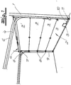
- Sectional door shown in its basic structure consists of a door frame 1, a door leaf 2 of articulated sections 3, 3 ', connected to the door leaf 2 weight compensation device 4 and an electric door drive 5 for opening and closing movements of the door leaf 2.
- the weight compensation device 4 formed in the embodiment as Torsionsfedenivelle which is connected via pull cables with the lower section of the door leaf.
- Torblattschschsted ein section is guided as a head section 3 'to rails 6, which extend substantially horizontally to the door frame 1 and the frame side have a vertical end portion 7.
- the below the head section 3 'subsequent further sections 3 are guided with rollers 8 in guide rails 9, which have a vertical portion along the door frame 1, a horizontal portion parallel to the head section 3' leading rail 6 and an arc connecting the two sections.
- the door drive 5 is preferably laterally attached to the bottom in Torblattschschbach ein section 3 and has a mounted on the section 3 output shaft 10 with an end-side impeller 11.
- the driven wheel 11 engages in the guide rail 9 and moves the door leaf 2.
- the door drive 5 has a branching gear for two output shafts 10 which extend up to the two sides of the section 3 and have end wheels 11 engaging in the lateral guide rails 9.
- the door drive is arranged on one of the section 3 below the head section 3 '.
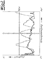
- Fig. 2 is the force acting on the door leaf tensile force during an opening movement of the door leaf shown.
- the course shown with a dashed line shows measured values on a sectional door with a designed as a ceiling tractor gate drive according to the prior art, which is connected with a coupling rod to the uppermost in the closed position section of the door leaf.
- a thicker, solid line the measured values for a sectional door are shown, which is equipped with a door drive according to the invention at the lowest section.
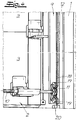
- the driven impeller 11 cooperates with a tensioned in the Fckenngsschiene 9 flexible power transmission line 18.
- the driven impeller 11 is formed as a pinion, which meshes with the power transmission line 18 designed as a toothed belt.
- the toothed belt 18 wraps around the pinion 11 partially.
- the live toothed belt 18 transmits the forces required for the opening and closing movements.
- a clamping station 20 is provided at one end.
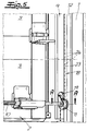
- Fig. 5 is the power transmission line 18 formed as a pearl necklace, which consists of a soul 23 and a plurality of each at the same distance to the soul 23 fixed bodies 24.
- the driven impeller 11 has a lateral flanks 25 limited throat-shaped tread 26, the bottom of the body 24 of the pearl necklace 18 adapted recesses 27 contains (see. Fig. 6 ).
- only one guide roller 19 is provided in the opening running direction in front of the driven wheel 11, so that the pearl chain 18 wraps around the driven wheel 11 in a Z-shaped manner.
- tension stations are provided at both ends of the pearl necklace.
Description
- Die Erfindung betrifft ein Sektionaltor mit
- Torzarge,
- einem Torblatt aus gelenkig verbundenen Sektionen,
- einer an das Torblatt angeschlossenen Gewichtsausgleichseinrichtung und
- einem elektrischen Torantrieb für Öffnungs- und Schließbewegungen des Torblattes,
- Sektionaltore der eingangs beschriebenen Art müssen den in der europäischen Norm EN 12453:2000 beschriebenen Sicherheitsanforderungen genügen. Darin ist festgelegt, dass während eines Öffnungs- bzw. Schließvorganges des Torblattes eine dynamische Kraft zwischen Schließkanten und Gegenschließkanten von maximal 400 N auftreten darf. Derart hohe Kräfte sind jedoch nur für einen Zeitraum von maximal 0,75 Sekunden zugelassen. Nach Ablauf dieser Zeitspanne ist keine statische Kraft erlaubt, die mehr als 150 N beträgt. Bei den in der Praxis bekannten Sektionaltoren mit den eingangs beschriebenen Merkmalen wird während einer regulären Öffnungs- bzw. Schließbewegung des Torblattes eine tolerierte statische Kraft von 150 N innerhalb des zulässigen Rahmens kurzzeitig häufig überschritten, so dass leistungsstarke Torantriebe eingesetzt werden müssen. Sofern die erforderliche Kraft zur Bewegung des Torblattes über eine Zeitdauer von mehr als 0,75 s hinweg mehr als 150 N beträgt, muss der Torantrieb durch eine Notabschaltung abgeschaltet werden. Bei einer Fehlfunktion der Notabschaltung besteht eine erhebliche Verletzungsgefahr. Problematisch ist auch, dass der im Rahmen der bekannten Maßnahmen an der obersten Torblattsektion befestigte Antrieb weit von der Gefahrenstelle, nämlich der unteren Schließkante entfernt ist, so dass ein langer Kraftfluss vom Motor über die gelenkig miteinander verbundenen Paneele bis zur Gefahrenstelle vorliegt. Eine Reduzierung der Antriebskraft des Motors schafft daher erst nach einer gewissen Verzögerungszeit eine entsprechende Entlastung an der Gefahrenstelle.
- Der vergleichsweise hohe Kraftbedarf während der Öffnungs- und Schließbewegungen bei bekannten Sektionaltoren beruht u.a. auf dem folgenden Sachverhalt. Die Kopfsektion des Torblattes weist an beiden Seiten jeweils eine Laufrolle auf, die in einer zugeordneten horizontalen Laufschiene geführt ist. Die horizontalen Laufschienen sind zargenseitig mit einem vertikalen Endabschnitt versehen, in den die Laufrollen der obersten Sektion bei einer Schließbewegung des Torblattes hineingezogen werden. Die in die vertikalen Endstücke eingeführten Laufrollen sichern die Kopfsektion in der Torblattschließstellung gegen ein unbefugtes Aufdrücken von außen. Bei einer Öffnungsbewegung des Torblattes müssen die Laufräder der Kopfsektion zunächst eine vertikale Strecke überwinden, bevor sie dann in den horizontalen Bereich der Laufschiene gelangen. Diese Hubbewegung zu Beginn der Öffnungsbewegung des Torblattes bildet ein technisches Problem für den elektrischen Torantrieb.
- Ein Sektionaltor mit den eingangs beschriebenen Merkmalen ist aus
EP-A 1 176 280 bekannt. Der elektrische Torantrieb ist entlang einer horizontalen Laufschiene verfahrbar und durch eine Kupplungsstange an die Kopfsektion angeschlossen. In der Torblattschließstellung ist die Kupplungsstange schräg zur Torblattebene ausgerichtet. Die bei einer Öffnungsbewegung des Torblattes mit der Kupplungsstange übertragene Zugkraft besitzt eine horizontale sowie eine vertikale Komponente. Infolge der vertikalen Komponente kann die Laufrolle der Kopfsektion mit einer Fahrbewegung des Torantriebes aus dem vertikalen Endabschnitt der vertikalen Laufschiene herausgezogen werden. Jedoch sind leistungsstarke Torantriebe erforderlich, die das bereits beschriebene Gefahrenpotential aufweisen. Nachteilig ist bei der bekannten Anordnung auch, dass die Kopfsektion in Torblattschließstellung und der vertikale Endabschnitt der Laufschiene zu Beginn einer Öffnungsbewegung großen Querkräften ausgesetzt sind. - Bei einem aus
US 2 015 402 bekannten Sektionaltor ist die Kopfsektion des Torblatts an Laufschienen geführt, die sich im Wesentlichen horizontal bis zur Torzarge erstrecken. An den horizontalen Laufschienen sind keine vertikalen Endabschnitte vorgesehen. Für Öffnungs- und Schließbewegungen des Torblatts ist ein Torantrieb vorgesehen, der entweder an der Kopfsektion oder einer Sektion unterhalb der Kopfsektion angeschlossen ist und ein als Ritzel ausgebildetes angetriebenes Laufrad aufweist. Das angetriebene Laufrad kämmt mit einer profilierten Fläche, die entlang einer Laufschiene oder Führungsschiene angeordnet ist. - Der Erfindung liegt die Aufgabe zugrunde, ein Sektionaltor mit den eingangs beschriebenen Merkmalen anzugeben, von dem eine reduzierte Verletzungsgefahr ausgeht. Dabei soll in jeder Stellung des Torblattes während einer Öffnungs- und Schließbewegung eine günstige Krafteinleitung von dem Torantrieb auf das Torblatt gewährleistet sein.
- Gegenstand der Erfindung und Lösung dieser Aufgabe ist ein Sektionaltor nach Anspruch 1.
- Erfindungsgemäß ist der Torantrieb an einer der unterhalb der Kopfsektion angeschlossenen Sektionen befestigt und weist mindestens eine an der Sektion gelagerte Abtriebswelle mit einem endseitigen Laufrad auf, welches in die Führungsschiene der Sektion eingreift und das Torblatt bewegt.
- Erfindungsgemäß ist der Torantrieb an der Torblattinnenfläche einer Sektion fest montiert und treibt ein Laufrad an, das in eine der Führung der Sektionen dienende Führungsschiene eingreift. Die Führungsschiene besitzt einen vertikalen Abschnitt entlang der Torzarge, einen horizontalen Abschnitt parallel zu der die Kopfsektion führenden Laufschiene sowie einen die beiden Abschnitte verbindenden Bogen. Bei einer Schließbewegung des Torblattes läuft das angetriebene Laufrad in den vertikalen Abschnitt der Führungsschiene ein. Bei einer nachfolgenden Öffnungsbewegung werden die Laufrollen der Kopfsektion durch die zunächst vertikale Verfahrbewegung der angetriebenen Laufräder aus den gekröpften Endbereichen der horizontalen Laufschiene herausgehoben. Unter anderem können aufgrund der günstigen Krafteinleitung verhältnismäßig schwache Torantriebe eingesetzt werden, so dass die Gefahr einer Verletzung während einer Öffnungs- und Schließbewegung des Torblattes reduziert wird.
- Gemäß einer bevorzugten Ausführung der Erfindung ist der Torantrieb an der in Torblattschließstellung untersten Sektion befestigt. Überraschenderweise wird hierdurch auch die nach dem Herausheben der Laufrollen der Kopfsektion aus den gekröpften Endbereichen der horizontalen Laufschiene erforderliche Kraft zum Bewegen des Torblattes im Vergleich zum Stand der Technik deutlich reduziert. Durch die Anordnung des Torantriebes an der in Torblattschließstellung untersten Sektion liegt ferner ein kurzer Kraftfluss zwischen dem Torantrieb und der potentiellen Gefahrenstelle an der bodenseitigen Schließkante des Torblattes vor, so dass eine Abschaltung des Torantriebes zu einer sehr schnellen Entlastung an der Gefahrenstelle führt.
- Erfindungsgenmäß ist der Torantrieb so dimensioniert, dass die maximale Antriebskraft zum Bewegen des Torblattes nicht mehr als 150 N beträgt. Bei der Anordnung von zwei oder mehr Motoren erfolgt die Dimensionierung entsprechend so, dass die gesamte maximale Antriebskraft unterhalb des genannten Grenzwertes liegt. Bei der erfindungsgemäßen Anordnung des Torblattantriebes werden die genannten kritischen Kraftwerte von mehr als 150 N während des regulären Öffnungs- bzw. Schließvorganges eines Torblattes, das Standardabmessungen für eine Garage mit einem oder zwei PKW-Einstellplätzen aufweist, nicht erreicht, so dass die Funktion des Torblattes auch bei der reduzierten Antriebsleistung des Torantriebes gewährleistet ist. Der eingangs erläuterte dynamische Bereich zwischen 150 N und 400 N, innerhalb dessen ein erhöhtes Verletzungsrisiko vorliegt, kann somit niemals erreicht werden. Eine Notabschaltung bei einem Überschreiten des kritischen Wertes von 150 N über einen Zeitraum von mehr als 0,75 s hinweg ist daher entbehrlich. Alternativ kann die Notabschaltung auf einen niedrigeren Kraftbegrenzungswert eingestellt werden. Neben dem Vorteil, dass ein inhärent verletzungssicheres System vorliegt, bestehen aufgrund der Verwendung eines kleineren Torantriebes auch Kostenvorteile.
- Der Torantrieb kann ein Verzweigungsgetriebe für zwei Abtriebswellen aufweisen, die sich bis zu den beiden Seiten der Sektionen erstrecken und endseitige, in die Führungsschienen eingreifenden Laufräder aufweisen. Es ist auch möglich, dass an einer oder an beiden Seiten des Torblattes ein Torantrieb mit jeweils nur einer Abtriebswelle vorgesehen ist. Die Führungsschienen besitzen zweckmäßig ein C-förmiges Querschnittsprofil, wobei ein Schenkel des Profils als rinnenförmige Lauffläche ausgebildet ist und der andere Schenkel eine im Abstand zur Lauffläche angeordnete Stützfläche bildet.
- Erfindungsgemäß wirkt das angetriebene Laufrad mit einem in der Führungsschiene gespannten flexiblen Kraftübertragungsstrang zusammen. Bei dieser Ausführungsform sind in Öffnungslaufrichtung gesehen vor und/oder hinter dem angetriebenen Laufrad Führungsrollen vorgesehen, die das angetriebene Laufrad an den Kraftübertragungsstrang andrücken, so dass der Kraftübertragungsstrang das angetriebene Laufrad teilweise umschlingt. Beispielsweise kann vor oder hinter dem angetriebenen Laufrad eine Führungsrolle vorgesehen sein, so dass der Kraftübertragungsstrang das angetriebene Laufrad Z-förmig umschlingt. In diesem Fall sind an beiden Enden des Kraftübertragungsstranges Spannstationen zur Aufrechterhaltung der Spannung während eines Öffnungs- und Schließvorganges des Torblattes zweckmäßig. Ferner können vor und hinter dem angetriebenen Laufrad Führungsrollen vorgesehen sein, so dass der Kraftübertragungsstrang das angetriebene Laufrad schlaufenförmig umschlingt. In diesem Fall muss nur an einem Ende des Kraftübertragungsstranges eine Spannstation vorgesehen werden.
- Es bestehen auch verschiedene Möglichkeiten zur konstruktiven Gestaltung des angetriebenen Laufrades und des Kraftübertragungsstranges. Das angetriebene Laufrad kann als Ritzel ausgebildet sein, welches mit dem als Zahnriemen oder Kette ausgebildeten Kraftübertragungsstrang kämmt. Das angetriebene Laufrad kann alternativ auch eine von seitlichen Flanken begrenzte kehlförmige Lauffläche aufweisen, wobei dann der Kraftübertragungsstrang zweckmäßigerweise als Seil ausgebildet ist. Ferner ist es auch möglich, dass der Kraftübertragungsstrang als Perlenkette ausgebildet ist, die aus einer Seele und einer Vielzahl jeweils im gleichen Abstand an der Seele befestigten Körpern besteht, und dass das angetriebene Laufrad eine von seitlichen Flanken begrenzte kehlförmige Lauffläche aufweist, die im Laufgrund an die Körper der Perlenkette angepasste Vertiefungen enthält.
- Im Folgenden wird die Erfindung anhand einer lediglich ein Ausführungsbeispiel darstellenden Zeichnung erläutert. Es zeigen schematisch:
- Fig. 1
- Die Innenansicht eines erfindungsgemäßen Sektionaltores in einer perspektivischen Darstellung,
- Fig. 2
- ein Kräftediagramm der während einer Öffnungsbewegung eines Sektionaltores gemessenen Zugkraft,
- Fig. 3
- eine weitere Ausführung der Erfindung,
- Fig. 4 und 5
- weitere Ausgestaltungen der erfindungsgemäßen Anordnung, ebenfalls ausschnittsweise, und
- Fig. 6
- den Schnitt A-A in
Fig. 5 . - Das in den
Fig. 1 und3 dargestellte Sektionaltor besteht in seinem grundsätzlichen Aufbau aus einer Torzarge 1, einem Torblatt 2 aus gelenkig verbundenen Sektionen 3, 3', einer an das Torblatt 2 angeschlossenen Gewichtsausgleichsvorrichtung 4 und einem elektrischen Torantrieb 5 für Öffnungs- und Schließbewegungen des Torblattes 2. Die Gewichtsausgleichsvorrichtung 4 ist im Ausführungsbeispiel als Torsionsfedenivelle ausgebildet, die über Zugseile mit der unteren Sektion des Torblattes verbunden ist. - Die in Torblattschließstellung oberste Sektion ist als Kopfsektion 3' an Laufschienen 6 geführt, die sich im Wesentlichen horizontal bis zur Torzarge 1 erstrecken und zargenseitig einen vertikalen Endabschnitt 7 aufweisen. Die unterhalb der Kopfsektion 3' anschließenden weiteren Sektionen 3 sind mit Laufrollen 8 in Führungsschienen 9 geführt, die einen vertikalen Abschnitt entlang der Torzarge 1, einen horizontalen Abschnitt parallel zu der die Kopfsektion 3' führenden Laufschiene 6 sowie einen die beiden Abschnitte verbindenden Bogen aufweisen.
- Im Ausführungsbeispiel der
Fig. 1 ist der Torantrieb 5 an der in Torblattschließstellung untersten Sektion 3 vorzugsweise seitlich befestigt und weist eine an der Sektion 3 gelagerte Abtriebswelle 10 mit einem endseitigen Laufrad 11 auf. Das angetriebene Laufrad 11 greift in die Führungsschiene 9 ein und bewegt das Torblatt 2. Im Ausführungsbeispiel derFig. 3 weist der Torantrieb 5 ein Verzweigungsgetriebe für zwei Abtriebswellen 10 auf, die sich bis zu den beiden Seiten der Sektion 3 erstrecken und endseitige, in die seitlichen Führungsschienen 9 eingreifende Laufräder 11 aufweisen. Der Torantrieb ist an einer der unterhalb der Kopfsektion 3' angeschlossenen Sektion 3 angeordnet. - In
Fig. 2 ist die auf das Torblatt wirkende Zugkraft bei einer Öffnungsbewegung des Torblattes dargestellt. Der mit einer gestrichelten Linie dargestellte Verlauf zeigt Messwerte an einem Sektionaltor mit einem als Deckenschlepper ausgebildeten Torantrieb nach dem Stand der Technik, der mit einer Kupplungsstange an die in Schließstellung oberste Sektion des Torblattes angeschlossen ist. Mit einer dickeren, durchgezogenen Linie sind die Messwerte für ein Sektionaltor dargestellt, welches mit einem erfindungsgemäßen Torantrieb an der untersten Sektion ausgerüstet ist. Ein Vergleich der Messwerte macht deutlich, dass durch die erfindungsgemäße Anordnung die Kräfte für eine Bewegung des Torblattes deutlich gesenkt werden können, geringere Kraftschwankungen bei der Bewegung des Torblattes auftreten und ein sicherer Abstand zu der nach der europäischen Norm EN 12453:2000 zulässigen maximalen statischen Kraft von 150 N eingehalten wird. - In den Ausführungsbeispielen der
Fig. 4 bis 6 wirkt das angetriebene Laufrad 11 mit einem in der Führngsschiene 9 gespannten flexiblen Kraftübertragungsstrang 18 zusammen. - In
Fig. 4 ist das angetriebene Laufrad 11 als Ritzel ausgebildet, welches mit dem als Zahnriemen ausgebildeten Kraftübertragungsstrang 18 kämmt. Der Zahnriemen 18 umschlingt das Ritzel 11 teilweise. In Laufrichtung vor sowie hinter dem Ritzel sind Führungsrollen 19 vorgesehen, die ebenso wie die Laufrollen 8 der weiteren Sektionen 3 auf dem Rücken des Zahnriemens 18 laufen. Der unter Spannung stehende Zahnriemen 18 überträgt die für die Öffnungs- und Schließbewegungen erforderlichen Kräfte. Zur Spannung des Zahnriemens 18 ist an dessen einem Ende eine Spannstation 20 vorgesehen. - In
Fig. 5 ist der Kraftübertragungsstrang 18 als Perlenkette ausgebildet, die aus einer Seele 23 und einer Vielzahl jeweils im gleichen Abstand an der Seele 23 befestigten Körpern 24 besteht. Das angetriebene Laufrad 11 weist eine von seitlichen Flanken 25 begrenzte kehlförmige Lauffläche 26 auf, die im Laufgrund an die Körper 24 der Perlenkette 18 angepasste Vertiefungen 27 enthält (vgl.Fig. 6 ). In diesem Ausführungsbeispiel ist in Öffnungslaufrichtung gesehen vor dem angetriebenen Laufrad 11 lediglich eine Führungsrolle 19 vorgesehen, so dass die Perlenkette 18 das angetriebene Laufrad 11 Z-förmig umschlingt. Zur Aufrechterhaltung der Spannung während eines Öffnungs- und Schließvorganges des Torblattes 2 sind an beiden Enden der Perlenkette 18 Spannstationen vorgesehen.
Claims (7)
- Sektionaltor mitTorzarge (1),einem Torblatt (2) aus gelenkig verbundenen Sektionen (3, 3'),einer an das Torblatt (2) angeschlossenen Gewichtsausgleicheinsrichtung (4) undeinem elektrischen Torantrieb (5) für Öffnungs- und Schließbewegungen des Torblattes (2),wobei die in Torblattschließstellung oberste Sektion als Kopfsektion (3') an Laufschienen (6) geführt ist, die sich im Wesentlichen horizontal bis zur Torzarge (1) erstrecken und zargenseitig einen vertikalen Endabschnitt (7) aufweisen, wobei die Kopfsektion (3') des Torblatts (2) an beiden Seiten jeweils eine Laufrolle aufweist, die in der zugeordneten horizontalen Laufschiene (6) geführt ist und bei einer Schließbewegung des Torblatts in den vertikalen Endabschnitt (7) der Laufschiene (6) hineingezogen wird, und wobei die unterhalb der Kopfsektion (3') anschließenden weiteren Sektionen (3) mit Laufrollen (8) in Führungsschienen (9) geführt sind, die einen vertikalen Abschnitt entlang der Torzarge (1), einen horizontalen Abschnitt parallel zu der die Kopfsektion (3') führenden Laufschiene (6) sowie einen die beiden Abschnitte verbindenden Bogen aufweisen, dadurch gekennzeichnet, dass der Torantrieb (5) an einer der unterhalb der Kopfsektion (3') angeschlossenen Sektionen (3) befestigt ist und mindestens eine an der Sektion (3) gelagerte Antriebswelle (10) mit einem endseitigen Laufrad (11) aufweist, wobei das angetriebene Laufrad (11) in die Führungsschiene (9) der Sektionen (3) eingreift und das Torblatt (2) bewegt, dass das angetriebene Laufrad (11) mit einem in der Führungsschiene (9) gespannten flexiblen Kraftübertragungsstrang (18) zusammenwirkt, wobei in Öffnungslaufrichtung gesehen vor und/oder hinter dem angetriebenen Laufrad (11) eine Führungsrolle (19) vorgesehen ist, die das angetriebene Laufrad (11) an den Kraftübertragungsstrang (18) andrückt, so dass der Kraftübertragungsstrang (18) das angetriebene Laufrad (11) teilweise umschlingt, und dass der Torantrieb (5) so dimensioniert ist, dass die maximale Antriebskraft zum Bewegen des Torblatts (2) nicht mehr als 150 N beträgt.
- Sektionaltor nach Anspruch 1, dadurch gekennzeichnet, dass der Torantrieb (5) an der in Torblattschließstellung untersten Sektion (3) befestigt ist.
- Sektionaltor nach Anspruch 1 oder 2, dadurch gekennzeichnet, dass der Torantrieb (5) ein Verzweigungsgetriebe für zwei Abtriebswellen (10) aufweist, die sich bis zu den beiden Seiten der Sektion (3) erstrecken und endseitige, in die Führungsschienen (9) eingreifende Laufräder (11) aufweisen.
- Sektionaltor nach einem der Ansprüche 1 bis 3, dadurch gekennzeichnet, dass in Öffnungslaufrichtung gesehen vor oder hinter dem angetriebenen Laufrad (11) eine Führungsrolle (19) vorgesehen ist, so dass der Kraftübertragungsstrang das angetriebene Laufrad Z-förmig umschlingt, und dass an beiden Enden des Kraftübertragungsstranges (18) Spannstationen (20) zur Aufrechterhaltung der Spannung während eines Öffnungs- und Schließvorganges des Torblattes (2) vorgesehen sind.
- Sektionaltor nach einem der Ansprüche 1 bis 3, dadurch gekennzeichnet, dass vor und hinter dem angetriebenen Laufrad (11) Führungsrollen (19) vorgesehen sind, so dass der Kraftübertragungsstrang (18) das angetriebene Laufrad (11) schlaufenförmig umschlingt.
- Sektionaltor nach einem der Ansprüche 1 bis 5, dadurch gekennzeichnet, dass das angetriebene Laufrad (11) als Ritzel ausgebildet ist, welches mit dem als Zahnriemen oder Kette ausgebildeten Kraftübertragungsstrang (18) kämmt.
- Sektionaltor nach einem der Ansprüche 1 bis 5, dadurch gekennzeichnet, dass der Kraftübertragungsstrang (18) als Perlenkette ausgebildet ist, die aus einer Seele (23) und einer Vielzahl jeweils im gleichen Abstand der Seele (23) befestigten Körpern (24) besteht, und dass das angetriebene Laufrad (11) eine von seitlichen Flanken (25) begrenzte kehlförmige Lauffläche (26) aufweist, die im Laufgrund an die Körper (24) der Perlenkette angepasste Vertiefungen (27) enthält.
Applications Claiming Priority (4)
| Application Number | Priority Date | Filing Date | Title |
|---|---|---|---|
| DE10312904 | 2003-03-22 | ||
| DE10312904 | 2003-03-22 | ||
| DE10349904 | 2003-10-25 | ||
| DE10349904.0A DE10349904C5 (de) | 2003-03-22 | 2003-10-25 | Sektionaltor |
Publications (3)
| Publication Number | Publication Date |
|---|---|
| EP1462601A2 EP1462601A2 (de) | 2004-09-29 |
| EP1462601A3 EP1462601A3 (de) | 2007-08-29 |
| EP1462601B1 true EP1462601B1 (de) | 2018-01-10 |
Family
ID=32826224
Family Applications (1)
| Application Number | Title | Priority Date | Filing Date |
|---|---|---|---|
| EP03026688.6A Expired - Lifetime EP1462601B1 (de) | 2003-03-22 | 2003-11-20 | Sektionaltor |
Country Status (3)
| Country | Link |
|---|---|
| US (2) | US7048029B2 (de) |
| EP (1) | EP1462601B1 (de) |
| JP (1) | JP2004285825A (de) |
Families Citing this family (22)
| Publication number | Priority date | Publication date | Assignee | Title |
|---|---|---|---|---|
| CN1236194C (zh) * | 2001-02-28 | 2006-01-11 | Vkr控股公司 | 屏蔽装置、用于屏蔽装置的驱动装置以及用于屏蔽装置的安装配件 |
| US20040059474A1 (en) * | 2002-09-20 | 2004-03-25 | Boorman Daniel J. | Apparatuses and methods for displaying autoflight information |
| FR2868460B1 (fr) * | 2004-03-31 | 2008-01-11 | Somfy Soc Par Actions Simplifi | Mecanisme de manoeuvre d'une porte, utilisation d'un frein dans un tel mecanisme et procede de regulation d'un couple moteur dans un tel mecanisme |
| US7321318B2 (en) * | 2004-03-31 | 2008-01-22 | The Boeing Company | Methods and systems for controlling the display of information at an aircraft flight deck |
| US20060144529A1 (en) * | 2005-01-04 | 2006-07-06 | Emerge Technologies, Inc. | Automated door openers |
| DE102005053560B4 (de) * | 2005-01-14 | 2012-07-12 | Novoferm Tormatic Gmbh | Elektromechanischer Antrieb für ein Tor oder dergleichen |
| US7441749B2 (en) * | 2005-12-08 | 2008-10-28 | Canimex, Inc. | Chain guide and drive mechanism including the same |
| GB0606579D0 (en) * | 2006-03-31 | 2006-05-10 | Cutler Daniel | Covering system |
| US7600344B2 (en) | 2006-05-08 | 2009-10-13 | Canimex, Inc. | Brake device with integrated anti-theft mechanism for garage doors and the like, and door assembly including the same |
| DE102008004050B4 (de) * | 2008-01-11 | 2011-04-07 | Sommer Antriebs- Und Funktechnik Gmbh | Antriebssystem für ein Tor |
| BE1018497A3 (fr) * | 2008-11-12 | 2011-02-01 | Becoflex S A | Dispositif de couverture d'une surface. |
| DE202009000929U1 (de) * | 2009-01-24 | 2009-03-26 | Sommer Antriebs- Und Funktechnik Gmbh | Antriebssystem für ein Tor |
| CN103352410B (zh) * | 2013-07-12 | 2015-09-02 | 河南师范大学 | 一种覆盖式机场防雪装置 |
| US9624708B2 (en) * | 2015-03-10 | 2017-04-18 | Ciw Enterprises, Inc. | Closure with roller endlock |
| ITUB20153409A1 (it) * | 2015-09-04 | 2017-03-04 | Like Blinds Srl Socio Unico | ?sistema di movimentazione per due pannelli? |
| CN111094685B (zh) * | 2017-09-06 | 2022-06-24 | 亚萨合莱自动门系统有限公司 | 分段式门操作器系统 |
| JP2022535596A (ja) * | 2019-06-10 | 2022-08-09 | アッサ・アブロイ・エントランス・システムズ・アーベー | ドア操作システム |
| WO2021144104A1 (en) * | 2020-01-15 | 2021-07-22 | Assa Abloy Entrance Systems Ab | Door operator system |
| WO2021156337A1 (en) * | 2020-02-06 | 2021-08-12 | Assa Abloy Entrance Systems Ab | Door operator system |
| EP3872585A1 (de) * | 2020-02-26 | 2021-09-01 | Bulinfo Eood | Vorrichtung zum öffnen oder schliessen eines fensters oder einer tür sowie ein system und verfahren zur steuerung und verwaltung der luftqualität von innenräumen |
| JP2023531040A (ja) * | 2020-06-25 | 2023-07-20 | アッサ・アブロイ・エントランス・システムズ・アーベー | ドア操作システム |
| WO2024057055A1 (en) * | 2022-09-18 | 2024-03-21 | Houtveen Beheer Achterveld B.V. | A device for operating a rolling door, a method for operating a rolling door, a storage room and a truck |
Family Cites Families (10)
| Publication number | Priority date | Publication date | Assignee | Title |
|---|---|---|---|---|
| US2064470A (en) * | 1931-01-17 | 1936-12-15 | Richards Wilcox Mfg Co | Overhead door |
| US2015402A (en) | 1932-02-01 | 1935-09-24 | Johanson Karl Erhard | Overhead door construction for garages and other buildings |
| US3012520A (en) * | 1959-11-18 | 1961-12-12 | Guy A Curtis | Reversible driving mechanism with automatic stop |
| DE3538947A1 (de) | 1985-11-02 | 1987-05-21 | Alten K | Tor, insb. sektionaltor, fuer gebaeude od.dgl. |
| US4625456A (en) * | 1986-02-20 | 1986-12-02 | Lucien Lafontaine | Power door operating device |
| US5036899A (en) * | 1990-08-02 | 1991-08-06 | Mullet Willis J | Panel garage door opening and closing |
| US5343923A (en) * | 1991-02-11 | 1994-09-06 | Hi-Fold Door Corporation | Automatic jamb latch mechanism for overhead bifold door |
| DE4123575A1 (de) | 1991-07-16 | 1993-01-21 | Kurz Rudolf Gmbh & Co | Antrieb fuer sektionaltore |
| DE20022292U1 (de) * | 2000-02-25 | 2001-06-28 | Rademacher Wilhelm | Schwenktor o.dgl., insbesondere Garagenschwenktor, sowie elektrische Antriebsvorrichtung dafür |
| ES2455990T3 (es) | 2000-07-28 | 2014-04-21 | Novoferm Gmbh | Puerta, en particular puerta de garaje |
-
2003
- 2003-11-20 EP EP03026688.6A patent/EP1462601B1/de not_active Expired - Lifetime
-
2004
- 2004-01-12 US US10/755,485 patent/US7048029B2/en not_active Expired - Fee Related
- 2004-03-16 JP JP2004074845A patent/JP2004285825A/ja not_active Withdrawn
-
2005
- 2005-11-29 US US11/288,682 patent/US8122933B2/en not_active Expired - Fee Related
Also Published As
| Publication number | Publication date |
|---|---|
| US20060076114A1 (en) | 2006-04-13 |
| US7048029B2 (en) | 2006-05-23 |
| US8122933B2 (en) | 2012-02-28 |
| US20040182528A1 (en) | 2004-09-23 |
| EP1462601A3 (de) | 2007-08-29 |
| JP2004285825A (ja) | 2004-10-14 |
| EP1462601A2 (de) | 2004-09-29 |
Similar Documents
| Publication | Publication Date | Title |
|---|---|---|
| EP1462601B1 (de) | Sektionaltor | |
| EP1886853B1 (de) | Fensterrollo mit Antrieb über den Fensterheber | |
| EP1981800B1 (de) | Parkbühne für kraftfahrzeuge | |
| EP0701649B1 (de) | Seilzug-fensterheber | |
| EP1184332B1 (de) | Fahrzeug-Hebebühne | |
| EP1176280B1 (de) | Tor, insbesondere Garagentor | |
| EP2634341A2 (de) | Falttor mit zwei oder mehreren in sich starren Faltladenelementen mit abwechselnd nicht ausknickenden und ausknickenden Elementkanten sowie Betätigungsvorrichtung hierfür | |
| WO2006136129A1 (de) | Torantrieb mit schubkette oder rückensteifer kette | |
| DE10349904C5 (de) | Sektionaltor | |
| DE10203904B4 (de) | Antriebsvorrichtung für Kraftfahrzeugschiebedächer | |
| DE3508175A1 (de) | Garagentor oder hallentor mit feder-hubmechanik | |
| DE102006013086A1 (de) | Beschlag für ein Fenster oder eine Tür | |
| EP1726560B1 (de) | Scherenhubtisch | |
| DE19949329C2 (de) | Schnellauftor | |
| DE10354255A1 (de) | Fensterheberseilzugbaugruppen | |
| EP1176279B1 (de) | Sektionaltor | |
| EP1366259B1 (de) | Sektionaltor | |
| DE2702032A1 (de) | Kipptor | |
| DE10115096C1 (de) | Toranlage mit einem entlang mindestens eines ortsfesten Rollenbocks geführten Tragprofil | |
| DE10248608B4 (de) | Seitensektionaltor mit elektrischem Torantrieb | |
| DE10003160C1 (de) | Tor mit elektrischem Torantrieb | |
| DE10330693B4 (de) | Sektionaltor | |
| DE10261083B3 (de) | Sektionaltor | |
| DE2824520C2 (de) | Transporteinheit für Hängebahnen | |
| EP1225292A2 (de) | Tor |
Legal Events
| Date | Code | Title | Description |
|---|---|---|---|
| PUAI | Public reference made under article 153(3) epc to a published international application that has entered the european phase |
Free format text: ORIGINAL CODE: 0009012 |
|
| AK | Designated contracting states |
Kind code of ref document: A2 Designated state(s): AT BE BG CH CY CZ DE DK EE ES FI FR GB GR HU IE IT LI LU MC NL PT RO SE SI SK TR |
|
| AX | Request for extension of the european patent |
Extension state: AL LT LV MK |
|
| PUAL | Search report despatched |
Free format text: ORIGINAL CODE: 0009013 |
|
| AK | Designated contracting states |
Kind code of ref document: A3 Designated state(s): AT BE BG CH CY CZ DE DK EE ES FI FR GB GR HU IE IT LI LU MC NL PT RO SE SI SK TR |
|
| AX | Request for extension of the european patent |
Extension state: AL LT LV MK |
|
| 17P | Request for examination filed |
Effective date: 20071206 |
|
| AKX | Designation fees paid |
Designated state(s): AT BE BG CH CY CZ DE DK EE ES FI FR GB GR HU IE IT LI LU MC NL PT RO SE SI SK TR |
|
| 17Q | First examination report despatched |
Effective date: 20110610 |
|
| REG | Reference to a national code |
Ref country code: DE Ref legal event code: R079 Ref document number: 50315730 Country of ref document: DE Free format text: PREVIOUS MAIN CLASS: E05F0015160000 Ipc: E05F0015670000 |
|
| RIC1 | Information provided on ipc code assigned before grant |
Ipc: E05F 15/676 20150101ALI20170407BHEP Ipc: E05D 15/24 20060101ALI20170407BHEP Ipc: E05F 15/67 20150101AFI20170407BHEP |
|
| GRAP | Despatch of communication of intention to grant a patent |
Free format text: ORIGINAL CODE: EPIDOSNIGR1 |
|
| INTG | Intention to grant announced |
Effective date: 20170621 |
|
| GRAS | Grant fee paid |
Free format text: ORIGINAL CODE: EPIDOSNIGR3 |
|
| GRAA | (expected) grant |
Free format text: ORIGINAL CODE: 0009210 |
|
| AK | Designated contracting states |
Kind code of ref document: B1 Designated state(s): AT BE BG CH CY CZ DE DK EE ES FI FR GB GR HU IE IT LI LU MC NL PT RO SE SI SK TR |
|
| REG | Reference to a national code |
Ref country code: GB Ref legal event code: FG4D Free format text: NOT ENGLISH |
|
| REG | Reference to a national code |
Ref country code: CH Ref legal event code: EP Ref country code: AT Ref legal event code: REF Ref document number: 962608 Country of ref document: AT Kind code of ref document: T Effective date: 20180115 |
|
| REG | Reference to a national code |
Ref country code: IE Ref legal event code: FG4D Free format text: LANGUAGE OF EP DOCUMENT: GERMAN |
|
| REG | Reference to a national code |
Ref country code: DE Ref legal event code: R096 Ref document number: 50315730 Country of ref document: DE |
|
| REG | Reference to a national code |
Ref country code: NL Ref legal event code: FP |
|
| REG | Reference to a national code |
Ref country code: DK Ref legal event code: T3 Effective date: 20180424 |
|
| PG25 | Lapsed in a contracting state [announced via postgrant information from national office to epo] |
Ref country code: FI Free format text: LAPSE BECAUSE OF FAILURE TO SUBMIT A TRANSLATION OF THE DESCRIPTION OR TO PAY THE FEE WITHIN THE PRESCRIBED TIME-LIMIT Effective date: 20180110 Ref country code: CY Free format text: LAPSE BECAUSE OF FAILURE TO SUBMIT A TRANSLATION OF THE DESCRIPTION OR TO PAY THE FEE WITHIN THE PRESCRIBED TIME-LIMIT Effective date: 20180110 Ref country code: ES Free format text: LAPSE BECAUSE OF FAILURE TO SUBMIT A TRANSLATION OF THE DESCRIPTION OR TO PAY THE FEE WITHIN THE PRESCRIBED TIME-LIMIT Effective date: 20180110 |
|
| PG25 | Lapsed in a contracting state [announced via postgrant information from national office to epo] |
Ref country code: BG Free format text: LAPSE BECAUSE OF FAILURE TO SUBMIT A TRANSLATION OF THE DESCRIPTION OR TO PAY THE FEE WITHIN THE PRESCRIBED TIME-LIMIT Effective date: 20180410 Ref country code: SE Free format text: LAPSE BECAUSE OF FAILURE TO SUBMIT A TRANSLATION OF THE DESCRIPTION OR TO PAY THE FEE WITHIN THE PRESCRIBED TIME-LIMIT Effective date: 20180110 |
|
| REG | Reference to a national code |
Ref country code: DE Ref legal event code: R097 Ref document number: 50315730 Country of ref document: DE |
|
| PG25 | Lapsed in a contracting state [announced via postgrant information from national office to epo] |
Ref country code: EE Free format text: LAPSE BECAUSE OF FAILURE TO SUBMIT A TRANSLATION OF THE DESCRIPTION OR TO PAY THE FEE WITHIN THE PRESCRIBED TIME-LIMIT Effective date: 20180110 Ref country code: RO Free format text: LAPSE BECAUSE OF FAILURE TO SUBMIT A TRANSLATION OF THE DESCRIPTION OR TO PAY THE FEE WITHIN THE PRESCRIBED TIME-LIMIT Effective date: 20180110 Ref country code: IT Free format text: LAPSE BECAUSE OF FAILURE TO SUBMIT A TRANSLATION OF THE DESCRIPTION OR TO PAY THE FEE WITHIN THE PRESCRIBED TIME-LIMIT Effective date: 20180110 |
|
| PLBE | No opposition filed within time limit |
Free format text: ORIGINAL CODE: 0009261 |
|
| STAA | Information on the status of an ep patent application or granted ep patent |
Free format text: STATUS: NO OPPOSITION FILED WITHIN TIME LIMIT |
|
| PG25 | Lapsed in a contracting state [announced via postgrant information from national office to epo] |
Ref country code: SK Free format text: LAPSE BECAUSE OF FAILURE TO SUBMIT A TRANSLATION OF THE DESCRIPTION OR TO PAY THE FEE WITHIN THE PRESCRIBED TIME-LIMIT Effective date: 20180110 Ref country code: CZ Free format text: LAPSE BECAUSE OF FAILURE TO SUBMIT A TRANSLATION OF THE DESCRIPTION OR TO PAY THE FEE WITHIN THE PRESCRIBED TIME-LIMIT Effective date: 20180110 |
|
| 26N | No opposition filed |
Effective date: 20181011 |
|
| PG25 | Lapsed in a contracting state [announced via postgrant information from national office to epo] |
Ref country code: SI Free format text: LAPSE BECAUSE OF FAILURE TO SUBMIT A TRANSLATION OF THE DESCRIPTION OR TO PAY THE FEE WITHIN THE PRESCRIBED TIME-LIMIT Effective date: 20180110 |
|
| REG | Reference to a national code |
Ref country code: DE Ref legal event code: R119 Ref document number: 50315730 Country of ref document: DE |
|
| REG | Reference to a national code |
Ref country code: DK Ref legal event code: EBP Effective date: 20181130 |
|
| REG | Reference to a national code |
Ref country code: CH Ref legal event code: PL |
|
| REG | Reference to a national code |
Ref country code: NL Ref legal event code: MM Effective date: 20181201 |
|
| GBPC | Gb: european patent ceased through non-payment of renewal fee |
Effective date: 20181120 |
|
| PG25 | Lapsed in a contracting state [announced via postgrant information from national office to epo] |
Ref country code: LU Free format text: LAPSE BECAUSE OF NON-PAYMENT OF DUE FEES Effective date: 20181120 Ref country code: MC Free format text: LAPSE BECAUSE OF FAILURE TO SUBMIT A TRANSLATION OF THE DESCRIPTION OR TO PAY THE FEE WITHIN THE PRESCRIBED TIME-LIMIT Effective date: 20180110 |
|
| REG | Reference to a national code |
Ref country code: BE Ref legal event code: MM Effective date: 20181130 |
|
| REG | Reference to a national code |
Ref country code: IE Ref legal event code: MM4A |
|
| PG25 | Lapsed in a contracting state [announced via postgrant information from national office to epo] |
Ref country code: CH Free format text: LAPSE BECAUSE OF NON-PAYMENT OF DUE FEES Effective date: 20181130 Ref country code: LI Free format text: LAPSE BECAUSE OF NON-PAYMENT OF DUE FEES Effective date: 20181130 Ref country code: NL Free format text: LAPSE BECAUSE OF NON-PAYMENT OF DUE FEES Effective date: 20181201 |
|
| PG25 | Lapsed in a contracting state [announced via postgrant information from national office to epo] |
Ref country code: DE Free format text: LAPSE BECAUSE OF NON-PAYMENT OF DUE FEES Effective date: 20190601 Ref country code: IE Free format text: LAPSE BECAUSE OF NON-PAYMENT OF DUE FEES Effective date: 20181120 Ref country code: DK Free format text: LAPSE BECAUSE OF NON-PAYMENT OF DUE FEES Effective date: 20181130 Ref country code: FR Free format text: LAPSE BECAUSE OF NON-PAYMENT OF DUE FEES Effective date: 20181130 |
|
| PG25 | Lapsed in a contracting state [announced via postgrant information from national office to epo] |
Ref country code: BE Free format text: LAPSE BECAUSE OF NON-PAYMENT OF DUE FEES Effective date: 20181130 |
|
| PG25 | Lapsed in a contracting state [announced via postgrant information from national office to epo] |
Ref country code: GB Free format text: LAPSE BECAUSE OF NON-PAYMENT OF DUE FEES Effective date: 20181120 |
|
| REG | Reference to a national code |
Ref country code: AT Ref legal event code: MM01 Ref document number: 962608 Country of ref document: AT Kind code of ref document: T Effective date: 20181120 |
|
| PG25 | Lapsed in a contracting state [announced via postgrant information from national office to epo] |
Ref country code: AT Free format text: LAPSE BECAUSE OF NON-PAYMENT OF DUE FEES Effective date: 20181120 |
|
| PG25 | Lapsed in a contracting state [announced via postgrant information from national office to epo] |
Ref country code: TR Free format text: LAPSE BECAUSE OF FAILURE TO SUBMIT A TRANSLATION OF THE DESCRIPTION OR TO PAY THE FEE WITHIN THE PRESCRIBED TIME-LIMIT Effective date: 20180110 |
|
| PG25 | Lapsed in a contracting state [announced via postgrant information from national office to epo] |
Ref country code: PT Free format text: LAPSE BECAUSE OF FAILURE TO SUBMIT A TRANSLATION OF THE DESCRIPTION OR TO PAY THE FEE WITHIN THE PRESCRIBED TIME-LIMIT Effective date: 20180110 |
|
| PG25 | Lapsed in a contracting state [announced via postgrant information from national office to epo] |
Ref country code: HU Free format text: LAPSE BECAUSE OF FAILURE TO SUBMIT A TRANSLATION OF THE DESCRIPTION OR TO PAY THE FEE WITHIN THE PRESCRIBED TIME-LIMIT; INVALID AB INITIO Effective date: 20031120 Ref country code: GR Free format text: LAPSE BECAUSE OF FAILURE TO SUBMIT A TRANSLATION OF THE DESCRIPTION OR TO PAY THE FEE WITHIN THE PRESCRIBED TIME-LIMIT Effective date: 20180110 |