EP1455047B2 - Einlauftrichter - Google Patents
Einlauftrichter Download PDFInfo
- Publication number
- EP1455047B2 EP1455047B2 EP04001773A EP04001773A EP1455047B2 EP 1455047 B2 EP1455047 B2 EP 1455047B2 EP 04001773 A EP04001773 A EP 04001773A EP 04001773 A EP04001773 A EP 04001773A EP 1455047 B2 EP1455047 B2 EP 1455047B2
- Authority
- EP
- European Patent Office
- Prior art keywords
- inlet funnel
- guide rail
- funnel
- inlet
- running rail
- Prior art date
- Legal status (The legal status is an assumption and is not a legal conclusion. Google has not performed a legal analysis and makes no representation as to the accuracy of the status listed.)
- Expired - Lifetime
Links
- 239000011324 bead Substances 0.000 description 2
- 230000001066 destructive effect Effects 0.000 description 1
Images

Classifications
-
- E—FIXED CONSTRUCTIONS
- E06—DOORS, WINDOWS, SHUTTERS, OR ROLLER BLINDS IN GENERAL; LADDERS
- E06B—FIXED OR MOVABLE CLOSURES FOR OPENINGS IN BUILDINGS, VEHICLES, FENCES OR LIKE ENCLOSURES IN GENERAL, e.g. DOORS, WINDOWS, BLINDS, GATES
- E06B9/00—Screening or protective devices for wall or similar openings, with or without operating or securing mechanisms; Closures of similar construction
- E06B9/02—Shutters, movable grilles, or other safety closing devices, e.g. against burglary
- E06B9/08—Roll-type closures
- E06B9/11—Roller shutters
- E06B9/17—Parts or details of roller shutters, e.g. suspension devices, shutter boxes, wicket doors, ventilation openings
-
- E—FIXED CONSTRUCTIONS
- E06—DOORS, WINDOWS, SHUTTERS, OR ROLLER BLINDS IN GENERAL; LADDERS
- E06B—FIXED OR MOVABLE CLOSURES FOR OPENINGS IN BUILDINGS, VEHICLES, FENCES OR LIKE ENCLOSURES IN GENERAL, e.g. DOORS, WINDOWS, BLINDS, GATES
- E06B9/00—Screening or protective devices for wall or similar openings, with or without operating or securing mechanisms; Closures of similar construction
- E06B9/56—Operating, guiding or securing devices or arrangements for roll-type closures; Spring drums; Tape drums; Counterweighting arrangements therefor
- E06B9/58—Guiding devices
Definitions
- the invention relates to an inlet funnel for guiding the lateral ends of a tank-forming rods in the inlet region in the running rail of a roll-up door or shutter.
- Such inlet funnel is for example from the FR 1 380 006 A known.
- roller doors and blinds In order to enter this during the unwinding of the tank in the rails and to guide him during unwinding funnels are provided on roller doors and blinds. These are usually connected to the cap by a pin-shaped element of the inlet funnel with beads force and / or positively fixed in the region of the visor, which is inserted into the track rail. They serve in particular the protection of the shutter.
- a connecting device between a roller shutter box and a guide rail for the roller shutter wherein a first connecting part to the body of the roller shutter box fastened and preferably to be arranged above the guide rail and a second connecting part is provided with a first end part, which is connectable to the guide rail and a second end part, which is connectable to the first connecting part in at least two predetermined positions. These positions are displaceable transversely to the roller shutter box in order to adjust the guide rails relative to the roller shutter box can.
- the object of the invention is therefore to provide a funnel, in which the risk no longer exists, that this is pushed with the visor up from the track.
- the inlet funnel should be easy to install and non-destructive can be removed from the track again.
- the feed hopper according to the invention is relatively inexpensive to produce, which is of great importance for such a component.
- the inlet funnel has anyway in a designated area of the visor (and indirectly via this in the track) entering pin-shaped element which rests in the inserted position on the running rail and on which the means for positive connection of the inlet funnel with the running rail can be arranged ,
- the invention consists in that the inlet funnel is connected by a snap-in connection with the running rail.
- Snap-in bring in the present case the advantage that they provide a good position assurance and also are inexpensive to implement. If necessary, the inlet funnel can be relatively easily removed by loosening the snap connection from the track without damaging any of the components.
- a preferred embodiment of the invention is that is provided as a means for positive connection of the inlet funnel with the running rail a resilient locking tab on the inlet funnel, which can be latched into a corresponding recess or behind a projection of the running rail.
- Another embodiment of the invention provides that is provided as a means for securing the inlet funnel in the running rail a resilient locking tab on the running rail, which can be latched into a corresponding recess or behind a projection of the inlet funnel.
- the inlet funnel 1 has a pin-shaped element 2, which enters into a corresponding area of the cap 8 intended for this purpose and secures the inlet funnel 1 in this non-positively and / or positively by means of beads 4.
- a resilient tab 5 is provided as a means 5, 6 for the positive connection of the inlet funnel 1 and running rail 3 on this pin-shaped element 2, which engages in a corresponding recess 6 of the running rail 3 and thus ensures the inlet funnel 1 positively in the running rail 3. By pressing on the resilient tab 5 through the recess 6, the connection can be released again.
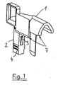
- the tank enters through the funnel portion 7 of the inlet funnel into the running rail 3.
- a projection may also be provided thereon or the tab may be provided on the running rail 3 and the recess 6 or the projection on the inlet funnel 1.
Landscapes
- Engineering & Computer Science (AREA)
- Structural Engineering (AREA)
- Architecture (AREA)
- Civil Engineering (AREA)
- Operating, Guiding And Securing Of Roll- Type Closing Members (AREA)
- Filling Or Emptying Of Bunkers, Hoppers, And Tanks (AREA)
- Centrifugal Separators (AREA)
- Jet Pumps And Other Pumps (AREA)
- Vessels, Lead-In Wires, Accessory Apparatuses For Cathode-Ray Tubes (AREA)
- Manufacture Of Electron Tubes, Discharge Lamp Vessels, Lead-In Wires, And The Like (AREA)
- Diaphragms For Electromechanical Transducers (AREA)
- Supply Devices, Intensifiers, Converters, And Telemotors (AREA)
- Other Liquid Machine Or Engine Such As Wave Power Use (AREA)
- Sheet Holders (AREA)
- Crystals, And After-Treatments Of Crystals (AREA)
- Valve Device For Special Equipments (AREA)
Description
- Die Erfindung betrifft einen Einlauftrichter zur Führung der seitlichen Enden der einen Panzer bildenden Stäbe im Eintrittsbereich in die Laufschiene eines Rolltores oder Rolladens.
- Ein derartiger Einlauftrichter ist beispielsweise aus der
FR 1 380 006 A - Um beim Abwickeln des Panzers diesen in die Laufschienen eintreten zu lassen und um ihn während des Abwickelns zu führen sind an Rolltoren und Rolläden Einlauftrichter vorgesehen. Diese werden üblicherweise mit der Blendkappe verbunden, indem ein zapfenförmiges Element des Einlauftrichters mit Wulsten kraft- und/oder formschlüssig in dem Bereich der Blendkappe festgelegt wird, der in die Laufschiene einsteckbar ist. Sie dienen insbesondere der Schonung des Rolladens.
- Bei herkömmlichen Rolltor- bzw. Rolladenantrieben erfolgt die Einstellung der oberen und unteren Endstellung, indem das Rolltor bzw. der Rolladen manuell in die jeweilige Endstellung gefahren und dort gestoppt wird.
- Mit der zunehmenden Verbreitung selbsteinstellender Rolltor- bzw. Rolladenantriebe, die automatisch die beiden Endstellungen anfahren, kann sich das Problem ergeben, daß bei dem Anfahren der unteren Endstellung der Rolltor- bzw. Rolladenantrieb den Einlauftrichter mit der Blendkappe aus der Laufschiene schiebt. Unter ungünstigen Umständen kann dies auch bei nichtmotorisierten Rolltoren bzw. Rolläden passieren.
- Aus der
FR 2 804 156 A1 - Aufgabe der Erfindung ist daher, einen Einlauftrichter zu schaffen, bei dem die Gefahr nicht mehr besteht, daß dieser mit der Blendkappe nach oben aus der Laufschiene geschoben wird. Andererseits soll der Einlauftrichter leicht montierbar sein und zerstörungsfrei wieder aus der Laufschiene entfernt werden können.
- Diese Aufgabe wird erfindungsgemäß durch einen Einlauftrichters gemäß Anspruch 1 gelöst.
- Zusätzlich zu den oben beschriebenen, bereits vorhandenen Mitteln zum kraftschlüssigen Verbinden des Einlauftrichters mit der Blendkappe wird im Rahmen der Erfindung vorgeschlagen, Mittel zum formschlüssigen Verbinden von Einlauftrichter und Laufschiene vorzusehen.
- Dies hat den Vorteil, daß Blendkappe, Einlauftrichter und Laufschiene miteinander verbunden sind, so daß ein Lösen eines dieser Elemente durch den Antrieb ausgeschlossen werden kann. Der erfindungsgemäße Einlauftrichter ist relativ kostengünstig herstellbar, was für ein derartiges Bauteil von großer Bedeutung ist.
- Der Einlauftrichter hat ohnehin ein in einen dafür vorgesehenen Bereich der Blendkappe (und über diese indirekt in die Laufschiene) eintretendes zapfenförmiges Element, das in eingeschobener Stellung an der Laufschiene anliegt und an dem auch die Mittel zum formschlüssigen Verbinden des Einlauftrichters mit der Laufschiene angeordnet werden können.
- Die Erfindung besteht darin, daß der Einlauftrichter durch eine Einrastverbindung mit der Laufschiene verbunden ist.
- Einrastverbindungen bringen im vorliegenden Fall den Vorteil mit sich, daß sie eine gute Lagesicherung ergeben und zudem kostengünstig realisierbar sind. Bei Bedarf kann der Einlauftrichter durch Lösen der Einrastverbindung relativ leicht aus der Laufschiene entfernt werden, ohne eines der Bauteile zu beschädigen.
- Eine bevorzugte Ausbildung der Erfindung besteht darin, daß als Mittel zum formschlüssigen Verbinden des Einlauftrichters mit der Laufschiene eine federnde Sicherungslasche an dem Einlauftrichter vorgesehen ist, die in eine entsprechende Aussparung oder hinter einem Vorsprung der Laufschiene einrastbar ist.
- Eine andere Ausbildung der Erfindung sieht vor, daß als Mittel zum Sichern des Einlauftrichters in der Laufschiene eine federnde Sicherungslasche an der Laufschiene vorgesehen ist, die in eine entsprechende Aussparung oder hinter einem Vorsprung des Einlauftrichters einrastbar ist.
- Nachfolgend wird ein Ausführungsbeispiel der Erfindung anhand von Zeichnungen beschrieben.
- Es zeigen
- Fig. 1
- eine perspektivische Darstellung eines erfindungsgemäßen Einlauftrichters,
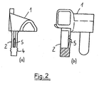
- Fig. 2a und Fig. 2b
- zwei um 90° versetzte Seitenansichten des Einlauftrichters gemäß
Fig. 1 , - Fig. 3a und Fig. 3b
- eine Draufsicht und eine Seitenansicht eines in eine Laufschiene eingebauten erfindungsgemäßen Einlauftrichters.
- Wie aus den
Fig. 1 bis 3 hervorgeht, weist der Einlauftrichter 1 ein zapfenförmiges Element 2 auf, das in einen entsprechenden, dafür vorgesehenen Bereich der Blendkappe 8 eintritt und den Einlauftrichter 1 in dieser kraft- und/oder formschlüssig durch Wülste 4 sichert. Zusätzlich ist als Mittel 5, 6 zum formschlüssigen Verbinden von Einlauftrichter 1 und Laufschiene 3 an diesem zapfenförmigen Element 2 eine federnde Lasche 5 vorgesehen, die in eine entsprechende Aussparung 6 der Laufschiene 3 eingreift und somit den Einlauftrichter 1 formschlüssig in der Laufschiene 3 sichert. Durch Drücken auf die federnde Lasche 5 durch die Aussparung 6 kann die Verbindung wieder gelöst werden. - Der Panzer tritt durch den Trichterbereich 7 des Einlauftrichters in die Laufschiene 3 ein.
- Alternativ zu der Aussparung 6 der Laufschiene 3 kann an dieser auch ein Vorsprung (nicht dargestellt) vorgesehen sein oder aber die Lasche an der Laufschiene 3 vorgesehen sein und die Aussparung 6 bzw. der Vorsprung an dem Einlauftrichter 1.
Claims (3)
- Einlauftrichter zur Führung der seitlichen Enden der einen Panzer bildenden Stäbe im Eintrittsbereich in die Laufschiene eines Rolltores oder Rolladens, dadurch gekennzeichnet, daß an einem in die Blendkappe (8) eintretenden zapfenförmigen Element (2) des Einlauftrichters (1) zum kraftschlüssigen Verbinden des Einlauftrichters(1) mit der Blendkappe (8) Mittel (5, 6) zum formschlüssigen Verbinden des Einlauftrichters (1) mit der Laufschiene (3) vorgesehen sind, wobei der Einlauftrichter (1) durch eine Einrastverbindung (5, 6) mit der Laufschiene (3) verbunden ist.
- Einlauftrichter gemäß Anspruch 1, dadurch gekennzeichnet, daß als Mittel (5, 6) zum formschlüssigen Verbinden des Einlauftrichters (1) mit der Laufschiene (3) eine federnde Sicherungslasche (5) an dem Einlauftrichter (1) vorgesehen ist, die in eine entsprechende Aussparung (6) oder hinter einem Vorsprung (6) der Laufschiene (3) einrastbar ist.
- Einlauftrichter gemäß Anspruch 1, dadurch gekennzeichnet, daß als Mittel (5, 6) zum Sichern des Einlauftrichters (1) in der Laufschiene (3) eine federnde Sicherungslasche (5) an der Laufschiene (3) vorgesehen ist, die in eine entsprechende Aussparung (6) oder hinter einem Vorsprung (6) des Einlauftrichters (1) einrastbar ist.
Priority Applications (1)
| Application Number | Priority Date | Filing Date | Title |
|---|---|---|---|
| SI200431292T SI1455047T2 (sl) | 2003-02-12 | 2004-01-28 | Vstopni lijak |
Applications Claiming Priority (2)
| Application Number | Priority Date | Filing Date | Title |
|---|---|---|---|
| DE20302277U | 2003-02-12 | ||
| DE20302277U DE20302277U1 (de) | 2003-02-12 | 2003-02-12 | Einlauftrichter |
Publications (4)
| Publication Number | Publication Date |
|---|---|
| EP1455047A2 EP1455047A2 (de) | 2004-09-08 |
| EP1455047A3 EP1455047A3 (de) | 2005-08-31 |
| EP1455047B1 EP1455047B1 (de) | 2009-09-09 |
| EP1455047B2 true EP1455047B2 (de) | 2012-11-14 |
Family
ID=7979983
Family Applications (1)
| Application Number | Title | Priority Date | Filing Date |
|---|---|---|---|
| EP04001773A Expired - Lifetime EP1455047B2 (de) | 2003-02-12 | 2004-01-28 | Einlauftrichter |
Country Status (7)
| Country | Link |
|---|---|
| EP (1) | EP1455047B2 (de) |
| AT (1) | ATE442508T1 (de) |
| DE (2) | DE20302277U1 (de) |
| ES (1) | ES2332511T5 (de) |
| PL (1) | PL207491B1 (de) |
| PT (1) | PT1455047E (de) |
| SI (1) | SI1455047T2 (de) |
Families Citing this family (4)
| Publication number | Priority date | Publication date | Assignee | Title |
|---|---|---|---|---|
| EP1518995B1 (de) * | 2003-09-29 | 2006-10-25 | Serplast S.A.S. Di Giovanni Marcon & C. | Modulares platzsparendes Wickelsystem und Verfahren zu seiner Installation |
| DE202005016059U1 (de) * | 2005-10-13 | 2006-02-02 | Veka Ag | Befestigungssystem für einen Aufsatzrollladenkasten |
| DE102010060897A1 (de) | 2010-11-30 | 2012-05-31 | Schlotterer Rollcom.De Gmbh & Co. Kg | Rolladensystem mit Lamelleneinlauftrichter |
| DE102012100089A1 (de) * | 2012-01-05 | 2013-07-11 | Lakal Gmbh | Einlaufelement |
Citations (3)
| Publication number | Priority date | Publication date | Assignee | Title |
|---|---|---|---|---|
| DE6930904U (de) † | 1969-07-31 | 1970-01-08 | Carl Goetze Rollofab | |
| DE2524736A1 (de) † | 1975-06-04 | 1976-12-16 | Willi Nagelschmidt | Einlauftrichter fuer die fuehrungsschienen von rollaeden |
| DE7835359U1 (de) † | 1978-11-29 | 1979-03-08 | Aro Leichtmetallbau-Gmbh, 8622 Burgkunstadt | Rolladenvorrichtung |
Family Cites Families (2)
| Publication number | Priority date | Publication date | Assignee | Title |
|---|---|---|---|---|
| FR1380006A (fr) | 1964-01-07 | 1964-11-27 | Ind Applic Materiali Estrusi S | Guide en matière plastique extrudée avec embouchure rapportée pour volet roulant |
| FR2804156B1 (fr) | 2000-01-25 | 2002-05-03 | Deprat Jean Sa | Dispositif de connexion entre un caisson de volet roulant et une glissiere de guidage |
-
2003
- 2003-02-12 DE DE20302277U patent/DE20302277U1/de not_active Expired - Lifetime
-
2004
- 2004-01-28 DE DE502004010017T patent/DE502004010017D1/de not_active Expired - Lifetime
- 2004-01-28 EP EP04001773A patent/EP1455047B2/de not_active Expired - Lifetime
- 2004-01-28 ES ES04001773T patent/ES2332511T5/es not_active Expired - Lifetime
- 2004-01-28 SI SI200431292T patent/SI1455047T2/sl unknown
- 2004-01-28 AT AT04001773T patent/ATE442508T1/de active
- 2004-01-28 PT PT04001773T patent/PT1455047E/pt unknown
- 2004-02-11 PL PL365092A patent/PL207491B1/pl not_active IP Right Cessation
Patent Citations (3)
| Publication number | Priority date | Publication date | Assignee | Title |
|---|---|---|---|---|
| DE6930904U (de) † | 1969-07-31 | 1970-01-08 | Carl Goetze Rollofab | |
| DE2524736A1 (de) † | 1975-06-04 | 1976-12-16 | Willi Nagelschmidt | Einlauftrichter fuer die fuehrungsschienen von rollaeden |
| DE7835359U1 (de) † | 1978-11-29 | 1979-03-08 | Aro Leichtmetallbau-Gmbh, 8622 Burgkunstadt | Rolladenvorrichtung |
Also Published As
| Publication number | Publication date |
|---|---|
| PT1455047E (pt) | 2009-12-10 |
| ES2332511T3 (es) | 2010-02-08 |
| SI1455047T2 (sl) | 2013-03-29 |
| ES2332511T5 (es) | 2013-03-15 |
| EP1455047A3 (de) | 2005-08-31 |
| PL207491B1 (pl) | 2010-12-31 |
| ATE442508T1 (de) | 2009-09-15 |
| DE20302277U1 (de) | 2003-04-17 |
| EP1455047A2 (de) | 2004-09-08 |
| PL365092A1 (en) | 2004-08-23 |
| DE502004010017D1 (de) | 2009-10-22 |
| EP1455047B1 (de) | 2009-09-09 |
| SI1455047T1 (sl) | 2010-02-26 |
Similar Documents
| Publication | Publication Date | Title |
|---|---|---|
| EP3427984A1 (de) | Schutzvorrichtung für einen fahrzeuginnenraum | |
| EP1455047B2 (de) | Einlauftrichter | |
| DE10000163C1 (de) | Als Vorsatzkasten ausgebildeter Rollladenkasten | |
| DE2919876A1 (de) | Fuehrungsanordnung zum linearen verstellen mindestens eines an einem traeger angeordneten gegenstandes, insbesondere zur parallelverstellung von moebeleinschueben | |
| DE19813034C1 (de) | Tierkäfig, insbesondere zur Haltung von Sauen | |
| EP2017104B1 (de) | Befestigungseinrichtung für eine bewegbare Scheibe eines Kraftfahrzeuges | |
| DE102005051997B4 (de) | Tor | |
| EP1947286B1 (de) | Rolladenkasten | |
| DE10044112C2 (de) | Vorrichtung zum Verbinden einer Scheibe mit einem Fensterheber | |
| EP4474610B1 (de) | Schutzvorrichtung für eine gebäudeöffnung und gebäudeöffnung mit einer solchen schutzvorrichtung | |
| EP2784262B1 (de) | Schrank mit Rollo | |
| DE19621817C2 (de) | Vorrichtung mit einem Sicherungselement zur axialen Sicherung eines Mitnehmers einer Wickelwelle | |
| DE29713191U1 (de) | Schiebeflügel mit einem aus Metallprofilen hergestellten Rahmen | |
| DE2540027C3 (de) | Haube zur spritzwasserdichten Belüftung von Innenräumen von Fahrzeugen o.dgl | |
| DE10052967B4 (de) | Chrashschutzvorrichtung für Schnelllaufrolltore | |
| DE3205417C2 (de) | Dachfenster für Kraftfahrzeuge | |
| DE202007008049U1 (de) | Führungsbaugruppe eines Kraftfahrzeugfensterhebers | |
| EP4474611A1 (de) | Gebäudeöffnung mit einer schutzvorrichtung | |
| DE4327424C1 (de) | Höheneinstelleinrichtung für den Deckel eines Hebeschiebe- bzw. eines Spoilerdaches von Fahrzeugen | |
| DE4235080C2 (de) | Duschabtrennung | |
| EP2860339B1 (de) | Aufschiebesicherung | |
| EP1588012B1 (de) | Distanzstück und verschattungseinrichtung, insbesondere vertikaljalousien oder vorhang, mit einem solchen distanzstück | |
| DE3217413A1 (de) | Vorrichtung zur befestigung von schwellenschienen an holzzargen | |
| DE4319824A1 (de) | Rolltor | |
| DE8803762U1 (de) | Fliegenschutzvorrichtung für Fenster oder Türen |
Legal Events
| Date | Code | Title | Description |
|---|---|---|---|
| PUAI | Public reference made under article 153(3) epc to a published international application that has entered the european phase |
Free format text: ORIGINAL CODE: 0009012 |
|
| AK | Designated contracting states |
Kind code of ref document: A2 Designated state(s): AT BE BG CH CY CZ DE DK EE ES FI FR GB GR HU IE IT LI LU MC NL PT RO SE SI SK TR |
|
| AX | Request for extension of the european patent |
Extension state: AL LT LV MK |
|
| PUAL | Search report despatched |
Free format text: ORIGINAL CODE: 0009013 |
|
| AK | Designated contracting states |
Kind code of ref document: A3 Designated state(s): AT BE BG CH CY CZ DE DK EE ES FI FR GB GR HU IE IT LI LU MC NL PT RO SE SI SK TR |
|
| AX | Request for extension of the european patent |
Extension state: AL LT LV MK |
|
| 17P | Request for examination filed |
Effective date: 20051221 |
|
| AKX | Designation fees paid |
Designated state(s): AT BE BG CH CY CZ DE DK EE ES FI FR GB GR HU IE IT LI LU MC NL PT RO SE SI SK TR |
|
| TPAC | Observations filed by third parties |
Free format text: ORIGINAL CODE: EPIDOSNTIPA |
|
| 17Q | First examination report despatched |
Effective date: 20080916 |
|
| GRAP | Despatch of communication of intention to grant a patent |
Free format text: ORIGINAL CODE: EPIDOSNIGR1 |
|
| GRAS | Grant fee paid |
Free format text: ORIGINAL CODE: EPIDOSNIGR3 |
|
| GRAA | (expected) grant |
Free format text: ORIGINAL CODE: 0009210 |
|
| AK | Designated contracting states |
Kind code of ref document: B1 Designated state(s): AT BE BG CH CY CZ DE DK EE ES FI FR GB GR HU IE IT LI LU MC NL PT RO SE SI SK TR |
|
| REG | Reference to a national code |
Ref country code: GB Ref legal event code: FG4D Free format text: NOT ENGLISH |
|
| REG | Reference to a national code |
Ref country code: CH Ref legal event code: EP |
|
| REG | Reference to a national code |
Ref country code: IE Ref legal event code: FG4D |
|
| REF | Corresponds to: |
Ref document number: 502004010017 Country of ref document: DE Date of ref document: 20091022 Kind code of ref document: P |
|
| RAP2 | Party data changed (patent owner data changed or rights of a patent transferred) |
Owner name: LAKAL GMBH |
|
| REG | Reference to a national code |
Ref country code: RO Ref legal event code: EPE |
|
| REG | Reference to a national code |
Ref country code: PT Ref legal event code: SC4A Free format text: AVAILABILITY OF NATIONAL TRANSLATION Effective date: 20091203 |
|
| REG | Reference to a national code |
Ref country code: CH Ref legal event code: NV Representative=s name: PATENTANWALT DIPL.-ING. (UNI.) WOLFGANG HEISEL |
|
| REG | Reference to a national code |
Ref country code: GR Ref legal event code: EP Ref document number: 20090403075 Country of ref document: GR |
|
| PG25 | Lapsed in a contracting state [announced via postgrant information from national office to epo] |
Ref country code: FI Free format text: LAPSE BECAUSE OF FAILURE TO SUBMIT A TRANSLATION OF THE DESCRIPTION OR TO PAY THE FEE WITHIN THE PRESCRIBED TIME-LIMIT Effective date: 20090909 Ref country code: SE Free format text: LAPSE BECAUSE OF FAILURE TO SUBMIT A TRANSLATION OF THE DESCRIPTION OR TO PAY THE FEE WITHIN THE PRESCRIBED TIME-LIMIT Effective date: 20090909 |
|
| NLT2 | Nl: modifications (of names), taken from the european patent patent bulletin |
Owner name: LAKAL GMBH Effective date: 20091202 |
|
| REG | Reference to a national code |
Ref country code: ES Ref legal event code: FG2A Ref document number: 2332511 Country of ref document: ES Kind code of ref document: T3 |
|
| PLBI | Opposition filed |
Free format text: ORIGINAL CODE: 0009260 |
|
| PG25 | Lapsed in a contracting state [announced via postgrant information from national office to epo] |
Ref country code: CY Free format text: LAPSE BECAUSE OF FAILURE TO SUBMIT A TRANSLATION OF THE DESCRIPTION OR TO PAY THE FEE WITHIN THE PRESCRIBED TIME-LIMIT Effective date: 20090909 |
|
| REG | Reference to a national code |
Ref country code: IE Ref legal event code: FD4D |
|
| REG | Reference to a national code |
Ref country code: SK Ref legal event code: T3 Ref document number: E 6590 Country of ref document: SK |
|
| 26 | Opposition filed |
Opponent name: ALUKON GMBH & CO. KG Effective date: 20100315 |
|
| REG | Reference to a national code |
Ref country code: HU Ref legal event code: AG4A Ref document number: E006973 Country of ref document: HU |
|
| PG25 | Lapsed in a contracting state [announced via postgrant information from national office to epo] |
Ref country code: EE Free format text: LAPSE BECAUSE OF FAILURE TO SUBMIT A TRANSLATION OF THE DESCRIPTION OR TO PAY THE FEE WITHIN THE PRESCRIBED TIME-LIMIT Effective date: 20090909 Ref country code: IE Free format text: LAPSE BECAUSE OF FAILURE TO SUBMIT A TRANSLATION OF THE DESCRIPTION OR TO PAY THE FEE WITHIN THE PRESCRIBED TIME-LIMIT Effective date: 20090909 |
|
| PLAX | Notice of opposition and request to file observation + time limit sent |
Free format text: ORIGINAL CODE: EPIDOSNOBS2 |
|
| PG25 | Lapsed in a contracting state [announced via postgrant information from national office to epo] |
Ref country code: DK Free format text: LAPSE BECAUSE OF FAILURE TO SUBMIT A TRANSLATION OF THE DESCRIPTION OR TO PAY THE FEE WITHIN THE PRESCRIBED TIME-LIMIT Effective date: 20090909 |
|
| PG25 | Lapsed in a contracting state [announced via postgrant information from national office to epo] |
Ref country code: MC Free format text: LAPSE BECAUSE OF NON-PAYMENT OF DUE FEES Effective date: 20100131 |
|
| GBPC | Gb: european patent ceased through non-payment of renewal fee |
Effective date: 20100128 |
|
| PLBB | Reply of patent proprietor to notice(s) of opposition received |
Free format text: ORIGINAL CODE: EPIDOSNOBS3 |
|
| PG25 | Lapsed in a contracting state [announced via postgrant information from national office to epo] |
Ref country code: GB Free format text: LAPSE BECAUSE OF NON-PAYMENT OF DUE FEES Effective date: 20100128 |
|
| RIC2 | Information provided on ipc code assigned after grant |
Ipc: E06B 9/17 20060101ALI20111121BHEP Ipc: E06B 9/58 20060101AFI20111121BHEP |
|
| PGFP | Annual fee paid to national office [announced via postgrant information from national office to epo] |
Ref country code: TR Payment date: 20120126 Year of fee payment: 9 |
|
| PUAH | Patent maintained in amended form |
Free format text: ORIGINAL CODE: 0009272 |
|
| STAA | Information on the status of an ep patent application or granted ep patent |
Free format text: STATUS: PATENT MAINTAINED AS AMENDED |
|
| 27A | Patent maintained in amended form |
Effective date: 20121114 |
|
| AK | Designated contracting states |
Kind code of ref document: B2 Designated state(s): AT BE BG CH CY CZ DE DK EE ES FI FR GB GR HU IE IT LI LU MC NL PT RO SE SI SK TR |
|
| REG | Reference to a national code |
Ref country code: CH Ref legal event code: AELC |
|
| REG | Reference to a national code |
Ref country code: DE Ref legal event code: R102 Ref document number: 502004010017 Country of ref document: DE Effective date: 20121114 |
|
| REG | Reference to a national code |
Ref country code: NL Ref legal event code: T3 |
|
| REG | Reference to a national code |
Ref country code: ES Ref legal event code: DC2A Ref document number: 2332511 Country of ref document: ES Kind code of ref document: T5 Effective date: 20130315 |
|
| REG | Reference to a national code |
Ref country code: SK Ref legal event code: T5 Ref document number: E 6590 Country of ref document: SK |
|
| PGFP | Annual fee paid to national office [announced via postgrant information from national office to epo] |
Ref country code: CZ Payment date: 20130117 Year of fee payment: 10 Ref country code: HU Payment date: 20130129 Year of fee payment: 10 Ref country code: RO Payment date: 20130115 Year of fee payment: 10 Ref country code: BG Payment date: 20130123 Year of fee payment: 10 |
|
| REG | Reference to a national code |
Ref country code: GR Ref legal event code: EP Ref document number: 20130400240 Country of ref document: GR Effective date: 20130327 |
|
| PGFP | Annual fee paid to national office [announced via postgrant information from national office to epo] |
Ref country code: GR Payment date: 20130121 Year of fee payment: 10 Ref country code: SI Payment date: 20130116 Year of fee payment: 10 Ref country code: SK Payment date: 20130117 Year of fee payment: 10 |
|
| REG | Reference to a national code |
Ref country code: SK Ref legal event code: MM4A Ref document number: E 6590 Country of ref document: SK Effective date: 20140128 |
|
| REG | Reference to a national code |
Ref country code: GR Ref legal event code: ML Ref document number: 20130400240 Country of ref document: GR Effective date: 20140801 |
|
| REG | Reference to a national code |
Ref country code: SI Ref legal event code: KO00 Effective date: 20140909 |
|
| PG25 | Lapsed in a contracting state [announced via postgrant information from national office to epo] |
Ref country code: RO Free format text: LAPSE BECAUSE OF NON-PAYMENT OF DUE FEES Effective date: 20140128 Ref country code: CZ Free format text: LAPSE BECAUSE OF NON-PAYMENT OF DUE FEES Effective date: 20140128 Ref country code: GR Free format text: LAPSE BECAUSE OF NON-PAYMENT OF DUE FEES Effective date: 20140801 |
|
| PG25 | Lapsed in a contracting state [announced via postgrant information from national office to epo] |
Ref country code: SI Free format text: LAPSE BECAUSE OF NON-PAYMENT OF DUE FEES Effective date: 20140129 Ref country code: SK Free format text: LAPSE BECAUSE OF NON-PAYMENT OF DUE FEES Effective date: 20140128 Ref country code: HU Free format text: LAPSE BECAUSE OF NON-PAYMENT OF DUE FEES Effective date: 20140129 |
|
| REG | Reference to a national code |
Ref country code: FR Ref legal event code: PLFP Year of fee payment: 13 |
|
| PG25 | Lapsed in a contracting state [announced via postgrant information from national office to epo] |
Ref country code: BG Free format text: LAPSE BECAUSE OF NON-PAYMENT OF DUE FEES Effective date: 20140131 |
|
| REG | Reference to a national code |
Ref country code: FR Ref legal event code: PLFP Year of fee payment: 14 |
|
| PG25 | Lapsed in a contracting state [announced via postgrant information from national office to epo] |
Ref country code: TR Free format text: LAPSE BECAUSE OF NON-PAYMENT OF DUE FEES Effective date: 20140128 |
|
| REG | Reference to a national code |
Ref country code: FR Ref legal event code: PLFP Year of fee payment: 15 |
|
| PGFP | Annual fee paid to national office [announced via postgrant information from national office to epo] |
Ref country code: LU Payment date: 20180124 Year of fee payment: 15 |
|
| PGFP | Annual fee paid to national office [announced via postgrant information from national office to epo] |
Ref country code: NL Payment date: 20180124 Year of fee payment: 15 |
|
| PGFP | Annual fee paid to national office [announced via postgrant information from national office to epo] |
Ref country code: DE Payment date: 20180126 Year of fee payment: 15 Ref country code: CH Payment date: 20180125 Year of fee payment: 15 Ref country code: ES Payment date: 20180220 Year of fee payment: 15 |
|
| PGFP | Annual fee paid to national office [announced via postgrant information from national office to epo] |
Ref country code: IT Payment date: 20180126 Year of fee payment: 15 Ref country code: AT Payment date: 20180122 Year of fee payment: 15 Ref country code: FR Payment date: 20180117 Year of fee payment: 15 Ref country code: BE Payment date: 20180124 Year of fee payment: 15 Ref country code: PT Payment date: 20180119 Year of fee payment: 15 |
|
| REG | Reference to a national code |
Ref country code: DE Ref legal event code: R119 Ref document number: 502004010017 Country of ref document: DE |
|
| REG | Reference to a national code |
Ref country code: CH Ref legal event code: PL |
|
| REG | Reference to a national code |
Ref country code: NL Ref legal event code: MM Effective date: 20190201 |
|
| REG | Reference to a national code |
Ref country code: AT Ref legal event code: MM01 Ref document number: 442508 Country of ref document: AT Kind code of ref document: T Effective date: 20190128 |
|
| PG25 | Lapsed in a contracting state [announced via postgrant information from national office to epo] |
Ref country code: LU Free format text: LAPSE BECAUSE OF NON-PAYMENT OF DUE FEES Effective date: 20190128 |
|
| REG | Reference to a national code |
Ref country code: BE Ref legal event code: MM Effective date: 20190131 |
|
| PG25 | Lapsed in a contracting state [announced via postgrant information from national office to epo] |
Ref country code: FR Free format text: LAPSE BECAUSE OF NON-PAYMENT OF DUE FEES Effective date: 20190131 Ref country code: NL Free format text: LAPSE BECAUSE OF NON-PAYMENT OF DUE FEES Effective date: 20190201 Ref country code: PT Free format text: LAPSE BECAUSE OF NON-PAYMENT OF DUE FEES Effective date: 20190729 Ref country code: DE Free format text: LAPSE BECAUSE OF NON-PAYMENT OF DUE FEES Effective date: 20190801 |
|
| PG25 | Lapsed in a contracting state [announced via postgrant information from national office to epo] |
Ref country code: BE Free format text: LAPSE BECAUSE OF NON-PAYMENT OF DUE FEES Effective date: 20190131 |
|
| PG25 | Lapsed in a contracting state [announced via postgrant information from national office to epo] |
Ref country code: CH Free format text: LAPSE BECAUSE OF NON-PAYMENT OF DUE FEES Effective date: 20190131 Ref country code: AT Free format text: LAPSE BECAUSE OF NON-PAYMENT OF DUE FEES Effective date: 20190128 Ref country code: LI Free format text: LAPSE BECAUSE OF NON-PAYMENT OF DUE FEES Effective date: 20190131 |
|
| PG25 | Lapsed in a contracting state [announced via postgrant information from national office to epo] |
Ref country code: IT Free format text: LAPSE BECAUSE OF NON-PAYMENT OF DUE FEES Effective date: 20190128 |
|
| REG | Reference to a national code |
Ref country code: ES Ref legal event code: FD2A Effective date: 20200310 |
|
| PG25 | Lapsed in a contracting state [announced via postgrant information from national office to epo] |
Ref country code: ES Free format text: LAPSE BECAUSE OF NON-PAYMENT OF DUE FEES Effective date: 20190129 |