EP1518995B1 - Modulares platzsparendes Wickelsystem und Verfahren zu seiner Installation - Google Patents
Modulares platzsparendes Wickelsystem und Verfahren zu seiner Installation Download PDFInfo
- Publication number
- EP1518995B1 EP1518995B1 EP03425629A EP03425629A EP1518995B1 EP 1518995 B1 EP1518995 B1 EP 1518995B1 EP 03425629 A EP03425629 A EP 03425629A EP 03425629 A EP03425629 A EP 03425629A EP 1518995 B1 EP1518995 B1 EP 1518995B1
- Authority
- EP
- European Patent Office
- Prior art keywords
- winding
- fixing
- modules
- guiding modules
- module
- Prior art date
- Legal status (The legal status is an assumption and is not a legal conclusion. Google has not performed a legal analysis and makes no representation as to the accuracy of the status listed.)
- Expired - Lifetime
Links
- 238000004804 winding Methods 0.000 title claims abstract description 117
- 238000000034 method Methods 0.000 title claims abstract description 8
- 239000000463 material Substances 0.000 claims abstract description 40
- 241000255925 Diptera Species 0.000 claims abstract description 14
- 238000003780 insertion Methods 0.000 claims description 22
- 230000037431 insertion Effects 0.000 claims description 22
- 239000000853 adhesive Substances 0.000 claims description 8
- 230000001070 adhesive effect Effects 0.000 claims description 8
- 230000005540 biological transmission Effects 0.000 claims description 4
- 239000004033 plastic Substances 0.000 claims description 2
- 238000005096 rolling process Methods 0.000 claims description 2
- 238000009434 installation Methods 0.000 description 6
- 230000010354 integration Effects 0.000 description 2
- 239000004809 Teflon Substances 0.000 description 1
- 229920006362 Teflon® Polymers 0.000 description 1
- 238000005452 bending Methods 0.000 description 1
- 230000001419 dependent effect Effects 0.000 description 1
- 230000000694 effects Effects 0.000 description 1
- 230000003993 interaction Effects 0.000 description 1
- 238000012986 modification Methods 0.000 description 1
- 230000004048 modification Effects 0.000 description 1
- 230000001360 synchronised effect Effects 0.000 description 1
Images
Classifications
-
- E—FIXED CONSTRUCTIONS
- E06—DOORS, WINDOWS, SHUTTERS, OR ROLLER BLINDS IN GENERAL; LADDERS
- E06B—FIXED OR MOVABLE CLOSURES FOR OPENINGS IN BUILDINGS, VEHICLES, FENCES OR LIKE ENCLOSURES IN GENERAL, e.g. DOORS, WINDOWS, BLINDS, GATES
- E06B9/00—Screening or protective devices for wall or similar openings, with or without operating or securing mechanisms; Closures of similar construction
- E06B9/52—Devices affording protection against insects, e.g. fly screens; Mesh windows for other purposes
- E06B9/54—Roller fly screens
-
- E—FIXED CONSTRUCTIONS
- E06—DOORS, WINDOWS, SHUTTERS, OR ROLLER BLINDS IN GENERAL; LADDERS
- E06B—FIXED OR MOVABLE CLOSURES FOR OPENINGS IN BUILDINGS, VEHICLES, FENCES OR LIKE ENCLOSURES IN GENERAL, e.g. DOORS, WINDOWS, BLINDS, GATES
- E06B9/00—Screening or protective devices for wall or similar openings, with or without operating or securing mechanisms; Closures of similar construction
- E06B9/02—Shutters, movable grilles, or other safety closing devices, e.g. against burglary
- E06B9/08—Roll-type closures
- E06B9/11—Roller shutters
- E06B9/17—Parts or details of roller shutters, e.g. suspension devices, shutter boxes, wicket doors, ventilation openings
- E06B9/17007—Shutter boxes; Details or component parts thereof
-
- E—FIXED CONSTRUCTIONS
- E06—DOORS, WINDOWS, SHUTTERS, OR ROLLER BLINDS IN GENERAL; LADDERS
- E06B—FIXED OR MOVABLE CLOSURES FOR OPENINGS IN BUILDINGS, VEHICLES, FENCES OR LIKE ENCLOSURES IN GENERAL, e.g. DOORS, WINDOWS, BLINDS, GATES
- E06B9/00—Screening or protective devices for wall or similar openings, with or without operating or securing mechanisms; Closures of similar construction
- E06B9/02—Shutters, movable grilles, or other safety closing devices, e.g. against burglary
- E06B9/08—Roll-type closures
- E06B9/11—Roller shutters
- E06B9/17—Parts or details of roller shutters, e.g. suspension devices, shutter boxes, wicket doors, ventilation openings
- E06B9/171—Rollers therefor; Fastening roller shutters to rollers
-
- E—FIXED CONSTRUCTIONS
- E06—DOORS, WINDOWS, SHUTTERS, OR ROLLER BLINDS IN GENERAL; LADDERS
- E06B—FIXED OR MOVABLE CLOSURES FOR OPENINGS IN BUILDINGS, VEHICLES, FENCES OR LIKE ENCLOSURES IN GENERAL, e.g. DOORS, WINDOWS, BLINDS, GATES
- E06B9/00—Screening or protective devices for wall or similar openings, with or without operating or securing mechanisms; Closures of similar construction
- E06B9/24—Screens or other constructions affording protection against light, especially against sunshine; Similar screens for privacy or appearance; Slat blinds
- E06B9/40—Roller blinds
- E06B2009/405—Two rollers
Definitions
- the present invention refers to a modular reduced-encumbrance winding system and to a procedure for installing such system for winding roller shutters and/or mosquito nets and the like in window and door frames, particularly to be applied to mobile houses, bungalows, boat-houses, campers, roulottes, trailers and caravans.
- winding systems belonging to the prior art has several problems either as regards the functional aspects or as regards the practicality of their operating laying.
- the winding systems with a single roll are highly bulky, which is an extremely negative aspect when they have to be installed on mobile houses, bungalows, boat-houses, campers, trailers and caravans that, due to their own nature, are characterized by main structures with limited resistance and thickness.
- they require devices with as more reduced encumbrance as possible, and they require the preparation of special housings for their operating laying.
- DE-A-2525600 which is the most relevant prior art, discloses a modular reduced-encumbrance winding system according to the preamble of Claim 1.
- Object of the present invention is solving the above prior-art problems, by providing a reduced-encumbrance winding system that allows using cases with smaller sizes and a lower side encumbrance.
- a further object of the present invention is providing a reduced-encumbrance winding system that, being dimensionally more compatible with the mobile house wall thickness, is more unobtrusive to be viewed guaranteeing a better aesthetic effect.
- Another object of the present invention is providing a reduced-encumbrance winding system composed of modular elements, already arranged for assembling in special kits and that allows the contemporary or deferred integration thereof with other elements, like mosquito net coilers.
- a further object of the present invention is providing a winding module of winding material able to be structurally fit to also guarantee an efficient operation when such winding material is of remarkable dimensions and/or weight, as in case of metallic shutters.
- an object of the present invention is providing an installation procedure of the parts belonging to the winding system according to the present invention, which allows their assembling and laying in a simple and fast way.
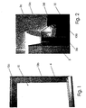
- the modular winding system 1 of the present invention allows, with extreme rapidity and simplicity, installing, on a window or on a door 10, a reduced-encumbrance winding module 2 of winding material 2a, to which it is possible to eventually apply a winding mosquito net using modules already arranged in an assembling kit.
- the modular reduced-encumbrance winding system 1 is composed of:
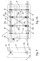
- the winding module 2 is composed of a containing case 20 provided with two side walls 2h, 2i on every one of which two symmetrically disposed insertion slots 2l, 2m, a plurality of holes 2o and two further holes 2p, 2q are arranged.
- Such slots 2l, 2m allow inserting the case on a channel that composes the lintel 10c of the frame of the door or the window 10, on which the system according to the present invention has to be installed, making its operating laying easy and fast.
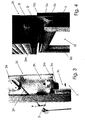
- two winding rods 2b, 2c of winding material 2a are rotatingly contained related to their respective longitudinal axes, that are arranged mutually parallel, with their own longitudinal axes perpendicular to the walls 2h, 2i and respectively passing through such walls 2h, 2i through the further holes 2p, 2q; moreover, such rods 2b, 2c are hinged on the walls 2h, 2i in order to be able to rotate around their own longitudinal axes; moreover, such rods 2b, 2c are mutually connected by at least one flexible transmission system 2d, which allows them to synchronously rotate, and an end of the winding material 2a is fixed on such transmission system 2d.
- each rod 2b, 2c is provided with at least two winding cylinders 2f in order to support and to enable the winding or the unwinding of the winding material 2a.
- the plurality of holes 2o on the walls 2h, 2i allow fixing a winding command system 2e, well known in the art, which, connected to one of the rods 2b, 2c, commands their rotation and accordingly the winding or the unwinding of the winding material 2a. Moreover, the symmetry of such plurality of holes 2o on both walls 2h, 2i allows fixing such command system 2e indifferently to the right or to the left of such case 20, according to users' demands.
- At least two sliding blocks are fixed through elastic means (not shown); such sliding blocks are of plastic material with low friction coefficient (i.e.: teflon) which allows a greater fluency and a smaller wear of the winding material 2a during winding and unwinding operations, especially when the winding module 2 is horizontally installed, namely with the plan that intersects the axes of the two rods 2b and 2c that is horizontally arranged.
- teflon plastic material with low friction coefficient
- the case 20 is provided with a safety cover (not shown) which is fixed through safety screws (not shown) in order to avoid its opening by malicious persons.
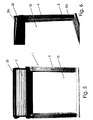
- each module 3, 5 is provided with a sliding groove 3a, 5a (the numbers respectively refer to the module 3 and to the further module 5), an insertion seat inserting one of the removable leading-in caps 3c, a clamp seat to clamp one of the removable upper limit stop pins 3d and fixing means.
- the modules 3 are provided to be clamped, through their own fixing means, respectively to the jambs 10a, 10b of the window or door 10, while the further modules 5 are provided to be clamped, through their own fixing means, to the respective modules 3 in case, subsequently, the further winding module 4 of the mosquito net is installed in union with the winding module 2.
- the sliding grooves 3a of the modules 3 are destined to guide the vertical slide of the winding material 2a and to maintain it in position, when only the winding module 2 is installed, or to guide the vertical slide of the mosquito net and to maintain it in position, when the winding module 2 and the further winding module 4 are contemporarily installed.
- the further sliding grooves 5a of the further modules 5 are provided to guide the vertical slide of the winding material 2a and to maintain it in position, when the further winding module 4 and the winding module 2 are contemporarily installed.
- the removable leading-in caps 3c are provided to be inserted, according to cases, in the aforesaid insertion seats in the upper end of the modules 3 or 5 and to guide the insertion of the winding material 2a inside the respective sliding grooves 3a of the modules 3, when only winding module 2 is installed, or to guide the insertion of the winding material 2a inside the respective further sliding grooves 5a of the further modules 5, when the winding module 2 and the further winding module 4 are contemporarily installed.
- Such two removable upper limit stop pins 3d are provided, according to cases, to be fixed in the aforesaid clamp seats in the inside side end of the modules 3 or 5 and to prevent, coming in contact with a limit stop pin (not shown) positioned on the two lower side ends of the winding material 2a, an excessive rewinding of such material 2a by the user from making such material 2a come out of the sliding grooves 3a, when only the winding module 2 is installed, or of the further sliding grooves 5a when the winding modules 2 and the further winding module 4 are contemporarily installed.
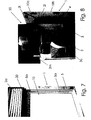
- such winding module 2 could be provided, depending on the length of the rods 2b, 2c and/or on the weight of the winding material 2a, with at least one support module 30 composed of two side vertical rods 30a, 30b joined by a central, "X"-spahed rib 30c and each vertical rod 30a, 30b is provided, into its opposite ends, with rolling means 30d (i.e.: through bushes or ball bearings) with low friction action in order to allow the rotation of the rods 2b, 2c passing in them: the number of such support modules 30 installed in the winding module 2 will be such as to limit the bending of the rods 2b, 2c, which could jeopardize the efficient operation of the module 2 itself.
- rolling means 30d i.e.: through bushes or ball bearings
- the aforesaid fixing means of such modules 3 and 5 include:
- the procedure according to the present invention allows very easily and quickly installing either the further winding module 2 only, or simultaneously the further winding module 2 and the winding module 4 of the mosquito net, or the further winding module 4 after having already installed the winding module 2.
- the installation procedure for the winding module 2 comprises the steps of:
- the installation procedure according to the present invention for the winding module 2 and the further winding module 4 simultaneously, comprises the steps of:
- the installation procedure for the further winding module 4 only afterwards, namely after having already installed the winding module 2, comprises the steps of:
Landscapes
- Engineering & Computer Science (AREA)
- Structural Engineering (AREA)
- Architecture (AREA)
- Civil Engineering (AREA)
- Life Sciences & Earth Sciences (AREA)
- Insects & Arthropods (AREA)
- Pest Control & Pesticides (AREA)
- Operating, Guiding And Securing Of Roll- Type Closing Members (AREA)
- Coil Winding Methods And Apparatuses (AREA)
- Replacement Of Web Rolls (AREA)
- Storage Of Web-Like Or Filamentary Materials (AREA)
- Wing Frames And Configurations (AREA)
Claims (8)
- Gruppe, die eine Architrav (10c) eines Tür- oder Fensterschlosses und ein modulares Aufrollsystem mit reduziertem Raumbedarf (1) enthält, das ein steuerbares Aufrollsystem (2e) und ein Aufrollmodul (2) mit aufrollbarem Material (2a) enthält, das genannte Aufrollmodul (2) enthält ein Behältergehäuse (20), das mit zwei Seitenwänden (2h, 2i) und zwei Rollstangen (2b, 2c) aus dem besagten aufrollbaren Material (2a) ausgestattet ist, die sich um ihre jeweiligen Längsachsen drehen und parallel zueinander im besagten Gehäuse (20) angeordnet sind, wobei die besagten Längsachsen senkrecht liegen und auf den besagten Seitenwänden (2h, 2i) angelenkt und durch ein biegsames Übertragungssystem (2d) verbunden sind, und das genannte steuerbare Aufrollsystem (2e) ist mit einer der genannten Rollstangen (2b, 2c) verbunden, um deren Drehung zu steuern, das genannte aufrollbare Material (2a) ist an einem ersten Endstück des besagten biegsamen Übertragungssystems (2d) befestigt, und das besagte Aufrollmodul ist mit zwei Führungsmodulen (3) ausgestattet, jedes der besagten Führungsmodule (3) ist mit einer Laufrille (3a) ausgestattet und verfügt über Befestigungsvorrichtungen für die Befestigung jedes der genannten Module (3) an einem entsprechenden externen vertikalen Pfosten (10a, 10b) eines Fenster- oder Türraums (10), jede der Seitenwände (2h, 2i) ist dadurch gekennzeichnet, dass sie mindestens zwei Einführungsschlitze (2l, 2m) hat, jeder der Einführungsschlitze (2l, 2m) ermöglicht die Einführung des Gehäuses (20) auf einen Kanal, der eine Architrav (10c) eines Tür- oder Fensterschlosses (10) bildet, jede der genannten Wände (2h, 2i) ist mit mehreren Löchern (2o), die für die Befestigung des genannten steuerbaren Aufrollsystems (2e) dienen, und mit weiteren zwei Löchern (2p, 2q) ausgestattet, die Rollstangen (2b, 2c) kommen entsprechend aus den besagten zwei weiteren Löchern (2p, 2q) heraus und sind mit mindestens zwei Rollzylindern (2f) ausgestattet; das besagte aufrollbare Material ist an einem zweiten Endstück gegenüber dem ersten Endstück mit mindestens einem Anschlagbolzen ausgestattet, das genannte Aufrollmodul ist mit einer Sicherheitsabdeckung des besagten Gehäuses (20) ausgestattet; zwei abnehmbare Schrägverschlüsse (3c); zwei abnehmbare obere Anschlagbolzen (3d); die beiden Führungsmodule sind mit einer Aufnahme für die Einführung eines der abnehmbaren Schrägverschlüsse (3c) und einer Befestigungsaufnahme für die genannten abnehmbaren oberen Anschlagbolzen (3d) ausgestattet, der genannte abnehmbare obere Anschlagbolzen (3d) muss mit dem besagten Anschlagbolzen aus dem besagten aufrollbaren Material (2a) in Berührung kommen und das Herauslaufen des besagten aufrollbaren Materials (2a) aus der genannten Laufrille (3a) vermeiden.
- Gruppe gemäß Patentanspruch 1, die dadurch gekennzeichnet ist, dass:- sie ein weiteres Aufrollmodul (4) eines Moskitonetzes enthält; und- zwei weitere Führungsmodule (5), jedes der genannten weiteren Führungsmodule (5) ist mit einer weiteren Laufrille (5a), weiteren Befestigungsvorrichtungen für die Befestigung des besagten weiteren Führungsmoduls (5) an einem entsprechenden Führungsmodul (3), einer Aufnahme für die Einführung eines der besagten abnehmbaren Schrägverschlüsse (3c) und einer Aufnahme für die Befestigung eines der besagten abnehmbaren oberen Anschlagbolzen (3d) ausgestattet, der genannte abnehmbare obere Anschlagbolzen (3d) muss mit dem genannten Anschlagbolzen aus dem besagten aufrollbaren Material (2a) in Berührung kommen und das Herauslaufen des besagten aufrollbaren Materials (2a) aus der genannten weiteren Laufrille (5a) vermeiden.
- Gruppe gemäß Patentanspruch 1, die dadurch gekennzeichnet ist, dass sie mindestens ein Halterungsmodul (30) enthält, das aus zwei vertikalen seitlichen Pfosten (30a, 30b) besteht, die durch eine "X-förmige" mittlere Rippe (30c) verbunden sind, jeder der besagten Pfosten (30a, 30b) ist an seinen gegenüber liegenden Endstücken mit Rollvorrichtungen (30d) mit niedrigem Reibungswert ausgestattet, die die Drehung der genannten Stangen (2b, 2c) zulassen, die Anzahl der genannten Halterungsmodule (30), die in besagtem Aufrollmodul (2) installiert sind, hängt von der Länge der besagten Stangen (2b, 2c) und dem Gewicht des genannten aufrollbaren Materials (2a) ab.
- Gruppe gemäß Patentanspruch 1, die dadurch gekennzeichnet ist, dass die besagten Befestigungsvorrichtungen mehrere Schraubklammern (6) enthalten, die auf den genannten Pfosten (10a, 10b) und auf mindestens einer Außenfläche der besagten Führungsmodule (3) parallel zu den genannten Pfosten (10a, 10b) eingeschraubt werden und in mindestens eine Rille in Längsrichtung auf den besagten Führungsmodulen und den genannten weiteren Führungsmodulen (3, 5) eingreifen müssen.
- Gruppe gemäß Patentanspruch 1, die dadurch gekennzeichnet ist, dass am genannten Gehäuse (20) mit elastischen Mitteln mindestens zwei Gleitbacken aus Kunststoffmaterial mit niedrigem Reibungswert befestigt sind, diese Gleitbacken dienen dazu, den Lauf des aufrollbaren Materials (2a) zu unterstützen und zu ermöglichen.
- Installationsverfahren der Gruppe gemäß Patentanspruch 1, das dadurch gekennzeichnet ist, dass es folgende Phasen enthält:- Die besagten Pfosten (10a, 10b) vertikal und extern durchbohren, und die genannten Klammern (6) in die besagten Löcher einschrauben;- In der Nähe der besagten Klammern (6) an den genannten Pfosten (10a, 10b) einen Klebstoff auftragen;- Jedes der genannten Führungsmodule (3) an einem entsprechenden Pfosten (10a, 10b) befestigen, dazu die besagte Laufrille auf einer entsprechenden Serie der Klammern (6) einführen;- Das genannte Gehäuse (20) an der genannten Tür oder Fenster (10) befestigen, und die besagten Schlitze (2l, 2m) in ein Profil, das eine Architrav (10c) eines Tür- oder Fensterschlosses (10) bildet, einführen;- Das besagte Gehäuse (20) mit Nägeln, Schrauben oder Blöcken an einer Wand befestigen;- Das genannte Steuersystem (2e) an einer der genannten Wände (2h, 2i) befestigen;- Die genannten Schrägverschlüsse (3c) in die entsprechenden Aufnahmen für die Einführung der Module (3) einführen;- Das aufrollbare Material (2a) in die besagten Laufrillen (3a) einführen;- Die besagten oberen Anschlussbolzen (3d) in den entsprechenden Befestigungsaufnahmen der genannten Führungsmodule (3) befestigen;- Die besagte Wand durchbohren, um die Einführung einer Stellstange (2n) des besagten Steuersystems (2e) zu ermöglichen;- Die besagte Abdeckung auf dem genannten Gehäuse (20) befestigen.
- Installationsverfahren der Gruppe gemäß Patentanspruch 2, das dadurch gekennzeichnet ist, dass es folgende Phasen enthält:- Die besagten Pfosten (10a, 10b) vertikal und extern durchbohren, und die genannten Klammern (6) in die besagten Löcher einschrauben;- In der Nähe der besagten Klammern (6) an den genannten Pfosten (10a, 10b) einen Klebstoff auftragen;- Jedes der genannten Führungsmodule (3) an einem entsprechenden Pfosten (10a, 10b) befestigen, dazu die besagte Laufrille auf einer entsprechenden Serie der Klammern (6) einführen;- Die besagten Führungsmodule (3) vertikal und frontal durchbohren, und die genannten Klammern (6) in die besagten Löcher einschrauben;- In der Nähe der besagten Klammern (6) an den genannten Modulen (3) einen Klebstoff auftragen;- Jedes der besagten Module (5) an einem entsprechenden Führungsmodul (3) befestigen, dazu die genannte Laufrille auf einer entsprechenden Serie der Klammern (6) einführen, die auf einem der entsprechenden genannten Führungsmodule (3) aufgeschraubt sind;- Das genannte Gehäuse (20) an der genannten Tür oder Fenster (10) befestigen, und die besagten Schlitze (2l, 2m) in ein Profil, das eine Architrav (10c) eines Tür- oder Fensterschlosses (10) bildet, einführen;- Das besagte Gehäuse (20) mit Nägeln, Schrauben oder Blöcken an einer Wand befestigen;- Das genannte Steuersystem (2e) an einer der Wände (2h, 2i) befestigen;- Das genannte weitere Aufrollmodul (4) in einem Raum zwischen der besagten Architrav (10c) und dem besagten Gehäuse (20) befestigen;- Das genannte Moskitonetz in die besagten Laufrillen (3a) einführen;- Die genannten Schrägverschlüsse (3c) in die besagten entsprechenden Aufnahmen für die Einführung der besagten weiteren Führungsmodule (5) einführen;- Das aufrollbare Material (2a) in die besagten Laufrillen (5a) einführen;- Die besagten oberen Anschlussbolzen (3d) in den entsprechenden Befestigungsaufnahmen der genannten Führungsmodule (5) befestigen;- Die besagte Wand durchbohren, um die Einführung einer Stellstange (2n) des besagten Steuersystems (2e) zu ermöglichen;- Die besagte Abdeckung auf dem genannten Gehäuse (20) befestigen.
- Installationsverfahren der Gruppe gemäß Patentanspruch 6 und gemäß Patentanspruch 2, das dadurch gekennzeichnet ist, dass es folgende Phasen enthält:- Die besagte Abdeckung vom genannten Gehäuse (20) entfernen;- Die besagten oberen Anschlussbolzen (3d) von den entsprechenden Befestigungsaufnahmen der genannten Führungsmodule (3) entfernen;- Das aufrollbare Material (2a) aus den besagten Laufrillen (3a) herausziehen;- Die genannten Schrägverschlüsse (3c) aus den besagten entsprechenden Aufnahmen für die Einführung der besagten weiteren Führungsmodule (3) entfernen;- Die besagten Führungsmodule (3) vertikal und frontal durchbohren, und die genannten Klammern (6) in die besagten Löcher einschrauben;- In der Nähe der besagten Klammern (6) an den genannten Modulen (3) einen Klebstoff auftragen;- Jedes der besagten weiteren Führungsmodule (5) an einem entsprechenden Führungsmodul (3) befestigen, dazu die genannte Laufrille auf einer entsprechenden Serie der Klammern (6) einführen, die auf einem der entsprechenden genannten Führungsmodule (3) aufgeschraubt sind;- Das genannte weitere Aufrollmodul (4) in einem Raum zwischen der besagten Architrav (10c) und dem besagten Gehäuse (20) befestigen;- Das genannte Moskitonetz in die besagten Laufrillen (3a) einführen;- Die genannten Schrägverschlüsse (3c) in die besagten entsprechenden Aufnahmen für die Einführung der besagten weiteren Führungsmodule (5) einführen;- Das aufrollbare Material (2a) in die besagten weiteren Laufrillen (5a) einführen;- Die besagten oberen Anschlussbolzen (3d) in den entsprechenden Befestigungsaufnahmen der weiteren Führungsmodule (5) befestigen;- Die besagte Abdeckung auf dem genannten Gehäuse (20) befestigen.
Priority Applications (3)
| Application Number | Priority Date | Filing Date | Title |
|---|---|---|---|
| AT03425629T ATE343700T1 (de) | 2003-09-29 | 2003-09-29 | Modulares platzsparendes wickelsystem und verfahren zu seiner installation |
| DE60309325T DE60309325D1 (de) | 2003-09-29 | 2003-09-29 | Modulares platzsparendes Wickelsystem und Verfahren zu seiner Installation |
| EP03425629A EP1518995B1 (de) | 2003-09-29 | 2003-09-29 | Modulares platzsparendes Wickelsystem und Verfahren zu seiner Installation |
Applications Claiming Priority (1)
| Application Number | Priority Date | Filing Date | Title |
|---|---|---|---|
| EP03425629A EP1518995B1 (de) | 2003-09-29 | 2003-09-29 | Modulares platzsparendes Wickelsystem und Verfahren zu seiner Installation |
Publications (2)
| Publication Number | Publication Date |
|---|---|
| EP1518995A1 EP1518995A1 (de) | 2005-03-30 |
| EP1518995B1 true EP1518995B1 (de) | 2006-10-25 |
Family
ID=34178710
Family Applications (1)
| Application Number | Title | Priority Date | Filing Date |
|---|---|---|---|
| EP03425629A Expired - Lifetime EP1518995B1 (de) | 2003-09-29 | 2003-09-29 | Modulares platzsparendes Wickelsystem und Verfahren zu seiner Installation |
Country Status (3)
| Country | Link |
|---|---|
| EP (1) | EP1518995B1 (de) |
| AT (1) | ATE343700T1 (de) |
| DE (1) | DE60309325D1 (de) |
Family Cites Families (7)
| Publication number | Priority date | Publication date | Assignee | Title |
|---|---|---|---|---|
| US625311A (en) | 1899-05-23 | James hunter annandale | ||
| CH503884A (de) | 1969-08-05 | 1971-02-28 | Griesser Ag | Rolladen |
| DE2024777A1 (de) | 1970-05-21 | 1971-12-02 | Bastgen, Aloys, 5560 Wittlich-Wengerohr | Rollverschlußauf- und Abwicklung über zwei Rollen |
| DE2525600A1 (de) * | 1975-04-25 | 1976-11-04 | Hartmann & Cie Ag Biel | Rolladen |
| CH617245A5 (de) * | 1977-04-25 | 1980-05-14 | Griesser Ag | |
| DE3433846A1 (de) * | 1984-09-14 | 1986-03-27 | Hörmann KG Bielefeld, 4800 Bielefeld | Aufnahmespeicher fuer die einzelnen glieder eines rolltores |
| DE20302277U1 (de) * | 2003-02-12 | 2003-04-17 | Karl Achenbach GmbH & Co. KG, 66117 Saarbrücken | Einlauftrichter |
-
2003
- 2003-09-29 EP EP03425629A patent/EP1518995B1/de not_active Expired - Lifetime
- 2003-09-29 DE DE60309325T patent/DE60309325D1/de not_active Expired - Lifetime
- 2003-09-29 AT AT03425629T patent/ATE343700T1/de not_active IP Right Cessation
Also Published As
| Publication number | Publication date |
|---|---|
| ATE343700T1 (de) | 2006-11-15 |
| EP1518995A1 (de) | 2005-03-30 |
| DE60309325D1 (de) | 2006-12-07 |
Similar Documents
| Publication | Publication Date | Title |
|---|---|---|
| EP1640554B1 (de) | Hochkurbelbare abschirmvorrichtung | |
| US20120012260A1 (en) | Retractable shade assembly with adjustable side guides | |
| EP0221816A2 (de) | Automatischer Insektenschutz für Türen und Fenster | |
| US20030173036A1 (en) | Blind and methods for operating thereof | |
| DE102015117548B4 (de) | Verschlussvorrichtung und Verfahren zur Montage einer Verschlussvorrichtung für eine Bauwerksöffnung | |
| CH712622A2 (it) | Apparato di copertura. | |
| KR101236750B1 (ko) | 롤 스크린 장치가 내장되게 한 시스템 창호 | |
| EP1518995B1 (de) | Modulares platzsparendes Wickelsystem und Verfahren zu seiner Installation | |
| KR20210075682A (ko) | 미세먼지 방지창호 및 그 시공방법 | |
| EP3056650A1 (de) | Insektenschutzgitter mit vorrichtung zum antreiben der netzführungskette und system zur erleichterung des zusammenbaus und zur korrektur der positionieranordnung | |
| IT201900002879A1 (it) | Dispositivo di tensionamento per zanzariere e tende avvolgibili | |
| DE102009052010A1 (de) | Renovierungsrolladen und Seitenteilmodul dafür | |
| KR20220082210A (ko) | 장력 조절이 가능한 주름 방충망 | |
| KR102669195B1 (ko) | 패브릭 텐션 장치 | |
| EP0959221A1 (de) | Insektenschutzgitter zur Schnellmontage | |
| KR102384844B1 (ko) | 공동주택의 발코니 안전장치 | |
| KR20050113338A (ko) | 착탈형 행거식 방충망 장치 | |
| KR102773121B1 (ko) | 차단막 텐션 조절장치 | |
| KR101667497B1 (ko) | 권취형 스크린 도어 | |
| JP3192327B2 (ja) | 網 戸 | |
| JP3192328B2 (ja) | 網 戸 | |
| KR200477448Y1 (ko) | 롤 타입 방충망 | |
| KR102597835B1 (ko) | 여닫이 주름 방충망 | |
| EP4074936B1 (de) | Seitenführung für eine bildschirmvorrichtung, bildschirmvorrichtung und verfahren zum installieren der bildschirmvorrichtung | |
| CN116623840B (zh) | 装配式隔断墙 |
Legal Events
| Date | Code | Title | Description |
|---|---|---|---|
| PUAI | Public reference made under article 153(3) epc to a published international application that has entered the european phase |
Free format text: ORIGINAL CODE: 0009012 |
|
| 17P | Request for examination filed |
Effective date: 20040602 |
|
| AK | Designated contracting states |
Kind code of ref document: A1 Designated state(s): AT BE BG CH CY CZ DE DK EE ES FI FR GB GR HU IE IT LI LU MC NL PT RO SE SI SK TR |
|
| AX | Request for extension of the european patent |
Extension state: AL LT LV MK |
|
| 17Q | First examination report despatched |
Effective date: 20050408 |
|
| AKX | Designation fees paid |
Designated state(s): AT BE BG CH CY CZ DE DK EE ES FI FR GB GR HU IE IT LI LU MC NL PT RO SE SI SK TR |
|
| GRAP | Despatch of communication of intention to grant a patent |
Free format text: ORIGINAL CODE: EPIDOSNIGR1 |
|
| GRAS | Grant fee paid |
Free format text: ORIGINAL CODE: EPIDOSNIGR3 |
|
| GRAA | (expected) grant |
Free format text: ORIGINAL CODE: 0009210 |
|
| AK | Designated contracting states |
Kind code of ref document: B1 Designated state(s): AT BE BG CH CY CZ DE DK EE ES FI FR GB GR HU IE IT LI LU MC NL PT RO SE SI SK TR |
|
| PG25 | Lapsed in a contracting state [announced via postgrant information from national office to epo] |
Ref country code: LI Free format text: LAPSE BECAUSE OF FAILURE TO SUBMIT A TRANSLATION OF THE DESCRIPTION OR TO PAY THE FEE WITHIN THE PRESCRIBED TIME-LIMIT Effective date: 20061025 Ref country code: BE Free format text: LAPSE BECAUSE OF FAILURE TO SUBMIT A TRANSLATION OF THE DESCRIPTION OR TO PAY THE FEE WITHIN THE PRESCRIBED TIME-LIMIT Effective date: 20061025 Ref country code: RO Free format text: LAPSE BECAUSE OF FAILURE TO SUBMIT A TRANSLATION OF THE DESCRIPTION OR TO PAY THE FEE WITHIN THE PRESCRIBED TIME-LIMIT Effective date: 20061025 Ref country code: CH Free format text: LAPSE BECAUSE OF FAILURE TO SUBMIT A TRANSLATION OF THE DESCRIPTION OR TO PAY THE FEE WITHIN THE PRESCRIBED TIME-LIMIT Effective date: 20061025 Ref country code: FI Free format text: LAPSE BECAUSE OF FAILURE TO SUBMIT A TRANSLATION OF THE DESCRIPTION OR TO PAY THE FEE WITHIN THE PRESCRIBED TIME-LIMIT Effective date: 20061025 Ref country code: AT Free format text: LAPSE BECAUSE OF FAILURE TO SUBMIT A TRANSLATION OF THE DESCRIPTION OR TO PAY THE FEE WITHIN THE PRESCRIBED TIME-LIMIT Effective date: 20061025 Ref country code: CZ Free format text: LAPSE BECAUSE OF FAILURE TO SUBMIT A TRANSLATION OF THE DESCRIPTION OR TO PAY THE FEE WITHIN THE PRESCRIBED TIME-LIMIT Effective date: 20061025 Ref country code: SI Free format text: LAPSE BECAUSE OF FAILURE TO SUBMIT A TRANSLATION OF THE DESCRIPTION OR TO PAY THE FEE WITHIN THE PRESCRIBED TIME-LIMIT Effective date: 20061025 Ref country code: NL Free format text: LAPSE BECAUSE OF FAILURE TO SUBMIT A TRANSLATION OF THE DESCRIPTION OR TO PAY THE FEE WITHIN THE PRESCRIBED TIME-LIMIT Effective date: 20061025 Ref country code: SK Free format text: LAPSE BECAUSE OF FAILURE TO SUBMIT A TRANSLATION OF THE DESCRIPTION OR TO PAY THE FEE WITHIN THE PRESCRIBED TIME-LIMIT Effective date: 20061025 |
|
| REG | Reference to a national code |
Ref country code: GB Ref legal event code: FG4D |
|
| REG | Reference to a national code |
Ref country code: CH Ref legal event code: EP |
|
| REG | Reference to a national code |
Ref country code: IE Ref legal event code: FG4D |
|
| REF | Corresponds to: |
Ref document number: 60309325 Country of ref document: DE Date of ref document: 20061207 Kind code of ref document: P |
|
| PG25 | Lapsed in a contracting state [announced via postgrant information from national office to epo] |
Ref country code: BG Free format text: LAPSE BECAUSE OF FAILURE TO SUBMIT A TRANSLATION OF THE DESCRIPTION OR TO PAY THE FEE WITHIN THE PRESCRIBED TIME-LIMIT Effective date: 20070125 Ref country code: SE Free format text: LAPSE BECAUSE OF FAILURE TO SUBMIT A TRANSLATION OF THE DESCRIPTION OR TO PAY THE FEE WITHIN THE PRESCRIBED TIME-LIMIT Effective date: 20070125 Ref country code: DK Free format text: LAPSE BECAUSE OF FAILURE TO SUBMIT A TRANSLATION OF THE DESCRIPTION OR TO PAY THE FEE WITHIN THE PRESCRIBED TIME-LIMIT Effective date: 20070125 |
|
| PG25 | Lapsed in a contracting state [announced via postgrant information from national office to epo] |
Ref country code: DE Free format text: LAPSE BECAUSE OF FAILURE TO SUBMIT A TRANSLATION OF THE DESCRIPTION OR TO PAY THE FEE WITHIN THE PRESCRIBED TIME-LIMIT Effective date: 20070126 |
|
| PG25 | Lapsed in a contracting state [announced via postgrant information from national office to epo] |
Ref country code: ES Free format text: LAPSE BECAUSE OF FAILURE TO SUBMIT A TRANSLATION OF THE DESCRIPTION OR TO PAY THE FEE WITHIN THE PRESCRIBED TIME-LIMIT Effective date: 20070205 |
|
| PG25 | Lapsed in a contracting state [announced via postgrant information from national office to epo] |
Ref country code: PT Free format text: LAPSE BECAUSE OF FAILURE TO SUBMIT A TRANSLATION OF THE DESCRIPTION OR TO PAY THE FEE WITHIN THE PRESCRIBED TIME-LIMIT Effective date: 20070326 |
|
| NLV1 | Nl: lapsed or annulled due to failure to fulfill the requirements of art. 29p and 29m of the patents act | ||
| REG | Reference to a national code |
Ref country code: CH Ref legal event code: PL |
|
| ET | Fr: translation filed | ||
| PLBE | No opposition filed within time limit |
Free format text: ORIGINAL CODE: 0009261 |
|
| STAA | Information on the status of an ep patent application or granted ep patent |
Free format text: STATUS: NO OPPOSITION FILED WITHIN TIME LIMIT |
|
| 26N | No opposition filed |
Effective date: 20070726 |
|
| PG25 | Lapsed in a contracting state [announced via postgrant information from national office to epo] |
Ref country code: MC Free format text: LAPSE BECAUSE OF NON-PAYMENT OF DUE FEES Effective date: 20070930 Ref country code: GR Free format text: LAPSE BECAUSE OF FAILURE TO SUBMIT A TRANSLATION OF THE DESCRIPTION OR TO PAY THE FEE WITHIN THE PRESCRIBED TIME-LIMIT Effective date: 20070126 |
|
| GBPC | Gb: european patent ceased through non-payment of renewal fee |
Effective date: 20070929 |
|
| REG | Reference to a national code |
Ref country code: FR Ref legal event code: ST Effective date: 20080531 |
|
| PG25 | Lapsed in a contracting state [announced via postgrant information from national office to epo] |
Ref country code: FR Free format text: LAPSE BECAUSE OF NON-PAYMENT OF DUE FEES Effective date: 20071001 Ref country code: IE Free format text: LAPSE BECAUSE OF NON-PAYMENT OF DUE FEES Effective date: 20071001 |
|
| PG25 | Lapsed in a contracting state [announced via postgrant information from national office to epo] |
Ref country code: GB Free format text: LAPSE BECAUSE OF NON-PAYMENT OF DUE FEES Effective date: 20070929 |
|
| PG25 | Lapsed in a contracting state [announced via postgrant information from national office to epo] |
Ref country code: EE Free format text: LAPSE BECAUSE OF FAILURE TO SUBMIT A TRANSLATION OF THE DESCRIPTION OR TO PAY THE FEE WITHIN THE PRESCRIBED TIME-LIMIT Effective date: 20061025 |
|
| PG25 | Lapsed in a contracting state [announced via postgrant information from national office to epo] |
Ref country code: IT Free format text: LAPSE BECAUSE OF NON-PAYMENT OF DUE FEES Effective date: 20070929 Ref country code: CY Free format text: LAPSE BECAUSE OF FAILURE TO SUBMIT A TRANSLATION OF THE DESCRIPTION OR TO PAY THE FEE WITHIN THE PRESCRIBED TIME-LIMIT Effective date: 20061025 Ref country code: LU Free format text: LAPSE BECAUSE OF NON-PAYMENT OF DUE FEES Effective date: 20070929 |
|
| PG25 | Lapsed in a contracting state [announced via postgrant information from national office to epo] |
Ref country code: TR Free format text: LAPSE BECAUSE OF FAILURE TO SUBMIT A TRANSLATION OF THE DESCRIPTION OR TO PAY THE FEE WITHIN THE PRESCRIBED TIME-LIMIT Effective date: 20061025 Ref country code: HU Free format text: LAPSE BECAUSE OF FAILURE TO SUBMIT A TRANSLATION OF THE DESCRIPTION OR TO PAY THE FEE WITHIN THE PRESCRIBED TIME-LIMIT Effective date: 20070426 |