EP1455021A1 - Elément séparateur métallique pour voies de circulation routière - Google Patents
Elément séparateur métallique pour voies de circulation routière Download PDFInfo
- Publication number
- EP1455021A1 EP1455021A1 EP04356024A EP04356024A EP1455021A1 EP 1455021 A1 EP1455021 A1 EP 1455021A1 EP 04356024 A EP04356024 A EP 04356024A EP 04356024 A EP04356024 A EP 04356024A EP 1455021 A1 EP1455021 A1 EP 1455021A1
- Authority
- EP
- European Patent Office
- Prior art keywords
- separating element
- metal
- box
- boxes
- element according
- Prior art date
- Legal status (The legal status is an assumption and is not a legal conclusion. Google has not performed a legal analysis and makes no representation as to the accuracy of the status listed.)
- Granted
Links
- 239000002184 metal Substances 0.000 title claims description 56
- 229910052751 metal Inorganic materials 0.000 title claims description 56
- 238000010276 construction Methods 0.000 claims description 3
- 241000826860 Trapezium Species 0.000 claims description 2
- 239000000543 intermediate Substances 0.000 claims 6
- 235000000396 iron Nutrition 0.000 description 13
- XEEYBQQBJWHFJM-UHFFFAOYSA-N Iron Chemical compound [Fe] XEEYBQQBJWHFJM-UHFFFAOYSA-N 0.000 description 8
- 230000004888 barrier function Effects 0.000 description 4
- 229910052742 iron Inorganic materials 0.000 description 4
- 238000000926 separation method Methods 0.000 description 4
- 229910000831 Steel Inorganic materials 0.000 description 1
- 238000004519 manufacturing process Methods 0.000 description 1
- 238000000034 method Methods 0.000 description 1
- 210000000056 organ Anatomy 0.000 description 1
- 230000003647 oxidation Effects 0.000 description 1
- 238000007254 oxidation reaction Methods 0.000 description 1
- 230000035939 shock Effects 0.000 description 1
- 239000010959 steel Substances 0.000 description 1
Images


Classifications
-
- E—FIXED CONSTRUCTIONS
- E01—CONSTRUCTION OF ROADS, RAILWAYS, OR BRIDGES
- E01F—ADDITIONAL WORK, SUCH AS EQUIPPING ROADS OR THE CONSTRUCTION OF PLATFORMS, HELICOPTER LANDING STAGES, SIGNS, SNOW FENCES, OR THE LIKE
- E01F15/00—Safety arrangements for slowing, redirecting or stopping errant vehicles, e.g. guard posts or bollards; Arrangements for reducing damage to roadside structures due to vehicular impact
- E01F15/02—Continuous barriers extending along roads or between traffic lanes
- E01F15/08—Continuous barriers extending along roads or between traffic lanes essentially made of walls or wall-like elements ; Cable-linked blocks
- E01F15/081—Continuous barriers extending along roads or between traffic lanes essentially made of walls or wall-like elements ; Cable-linked blocks characterised by the use of a specific material
- E01F15/085—Continuous barriers extending along roads or between traffic lanes essentially made of walls or wall-like elements ; Cable-linked blocks characterised by the use of a specific material using metal
-
- E—FIXED CONSTRUCTIONS
- E01—CONSTRUCTION OF ROADS, RAILWAYS, OR BRIDGES
- E01F—ADDITIONAL WORK, SUCH AS EQUIPPING ROADS OR THE CONSTRUCTION OF PLATFORMS, HELICOPTER LANDING STAGES, SIGNS, SNOW FENCES, OR THE LIKE
- E01F15/00—Safety arrangements for slowing, redirecting or stopping errant vehicles, e.g. guard posts or bollards; Arrangements for reducing damage to roadside structures due to vehicular impact
- E01F15/02—Continuous barriers extending along roads or between traffic lanes
- E01F15/04—Continuous barriers extending along roads or between traffic lanes essentially made of longitudinal beams or rigid strips supported above ground at spaced points
- E01F15/0407—Metal rails
- E01F15/0423—Details of rails
- E01F15/043—Details of rails with multiple superimposed members; Rails provided with skirts
Definitions
- the present invention relates to a metal separating element for traffic lanes, usable in particular as part of a temporary separation barrier, for the secure demarcation of a road or motorway construction site, i.e. physical separation, during the duration of a site, between one or more lanes reserved for vehicle traffic, and one or more other lanes or a strip of land, on which are carried out works such as repair or widening of the road.
- a modular separator concept has already been proposed. of traffic lanes made entirely of metal, in particular steel.
- a such a separator comprises support legs, on the sides of which are fixed metal slides, such as those commonly used as crash barriers, installed along traffic lanes road.
- connection between two consecutive unit elements, placed end to end is carried out by bolting, using two, four or six screws, and with respectively male and female centering guides, provided at the ends of these elements.
- One drawback of this connection method is the impossibility of dismantling and removing an interposed unitary separating element in a line of elements, precisely because of the centering guides which are obstacles to such a withdrawal.
- the connection device by bolting requires, for its use, significant resources, both in equipment (van, compressor, impact wrench, hardware) as in labor (three people being necessary simultaneously). The operating cost of these metallic separators therefore remain, currently, excessively high, which greatly limits their use.
- the present invention aims to remedy the aforementioned drawbacks metal separators, and its purpose is therefore to provide a system of more economical metallic separator, in its design and operation, also allowing the easy removal and replacement of an element interspersed in a file of elements.
- the subject of the invention is essentially an element metallic separator for traffic lanes, in particular a element usable for the temporary delimitation of a road construction site area or motorway, this separating element generally comprising known supports on both sides of which are fixed slides metallic, and being characterized, according to the invention, by the fact that it comprises two end boxes, and possibly at least one intermediate box, each consisting of two parallel, vertical, connected metal cheeks to each other, on each side of the box, by longitudinal bars which each have at least one hole for fixing, by bolting, of minus a slide that connects the boxes.
- the two metal cheeks of each box have the general shape of an isosceles trapezium, the large base of which position of use, is located at the bottom and serves as a floor support for the box.
- the two metal cheeks of each box are advantageously also connected to each other, at their vertices which correspond to the small base of the trapezoid, by a metal plate upper, whose side parts have lights for fixing by bolting the upper runners.
- this separating element comprises, on on each side, three superimposed slides connecting these boxes, with a lower slide fixed on a lower longitudinal bar, a slide intermediate fixed on an intermediate longitudinal bar, and overlapping preferably the lower slide, and an upper slide fixed on a bar longitudinal upper and on a lateral part of the metal plate top of a box.
- the two metallic cheeks of its two end boxes are also connected by at least two tubular guides longitudinal, serving as housings and sliding guides for corresponding parts of a connecting device between separating elements consecutive, put end to end.
- connection device provided at one end of the separating element, can be presented as a connecting stirrup comprising a vertical metal plate on one side of which project parts elongated horizontal sections and arrangement corresponding to those of aforementioned tubular guides, these horizontal parts being slidably mounted in the tubular guides of the terminal box of the separating element to which belongs the connecting device, and being engaging in the guides corresponding tubulars of an adjacent terminal box, belonging to a another separating element to link to the previous one.
- the two cheeks of the two terminal boxes of the element separator are advantageously connected by three tubular guides longitudinal, comprising an upper tubular guide and two guides lower tubulars, arranged along the vertices of an isosceles triangle, the vertical metal plate of the connecting bracket bearing on one of its faces three elongated longitudinal parts of arrangement corresponding to that of the three tubular guides.
- these longitudinal tubular guides consist of horizontal metal tubes, of section rectangular, the ends of which are welded to the edge of openings corresponding rectangles, arranged in the two cheeks of each terminal box, while the corresponding parts of the connecting device between separating elements are constituted by flat irons, each of length slightly greater than twice the length of one of the tubes mentioned above, the flat bars being welded to one face of the metal plate vertical of the connecting bracket.
- This vertical metal plate still advantageously carries an operating handle, on its face opposite to that provided with the parts horizontal elongated, in particular constituted by flat irons.
- the metallic separating element according to the invention can be presented as a relatively short separating element, comprising two boxes terminals and a single intermediate box, connected together, on their two sides, by side rails whose length is equal to the length total of the separating element.
- the separator element metallic object of the invention is presented as a separating element relatively long, comprising two terminal boxes and a plurality of intermediate boxes, interconnected by side rails successive, of length approximately equal to a submultiple of the length totality of the separating element, the ends of these slides overlapping at the level of intermediate boxes, on which they are simultaneously fixed by bolting.
- the invention thus provides a separating element metallic which has numerous advantages and particularly appreciable:
- this separating element is simple and therefore economical, especially due to the constitution of the boxes and the connection device from cut sheets, flat irons and tubes, the only bolts necessary being those carrying out the fixing of the rails on the boxes.
- the connecting device between separating elements placed end to end is also particularly simple, since it requires neither bolts nor articulation organs or the like.
- this metallic separating element also results from the use of conventional metal slides, from trade, in particular pre-existing metal slides, which can be recovered at lower cost, for example when replacing them with barriers concrete used as final separation.
- the boxes are particularly rigid, this applies in particular to terminal caissons, which are further stiffened by tubes connecting their two cheeks.
- the two ends of the metal separating element according to the invention are perfectly smooth, since these are metal cheeks exterior of the terminal boxes, which makes it easy to remove a separator element inserted in a continuous line of elements, and to put back possibly in place this element.
- the assembly thus produced between two elements consecutive dividers is particularly rigid, and it is secured by locking keys.
- separator design according to the invention it is in particular possible to constitute metallic separating elements "short", typically four meters long, with two boxes terminals and a single intermediate box, which produce an equivalent "module” to a standard concrete separator.
- the invention also allows the constitution of elements "long" metal separators, typically twelve meters long approx., with more intermediate boxes and slides overlapping, such elements being transportable on a road assembly with tractor and semi-trailer with handling crane, and their larger length to reduce the number of assembly operations between elements (for a given total length of the barrier to be produced).
- a metal separator element is designated overall for the reference 1.
- This element for example with a length of four meters, consists of three boxes 2, comprising two boxes terminals and an intermediate box, interconnected by slides side 3, 4 and 5 of which they constitute the support.
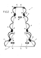
- the box 2 comprises two parallel vertical cheeks 6, made up of metal sheets cut in the general shape of a trapezoid isosceles, the large base of which is at the bottom (at ground level, when the use of the separating element 1).
- the two vertical cheeks 6 of the box 7 are connected to each other horizontally, on each side of box 2, by three flat bars superimposed 7, 8 and 9, the ends of which are welded to the inclined edges of the cheeks 6.
- Each flat iron 7, 8 and 9 has, at mid-length, a hole 10 for the fixing of the slides, as specified below.
- the respective vertices of the two vertical cheeks 6, which correspond to the small base of the trapezoid, are connected to each other by a upper plate 11 made of sheet metal, the horizontal middle part of which can have a large rectangular opening 12, the lateral parts of which, symmetrically inclined, each has two lights 13.
- the two vertical cheeks 6 are still connected to each other by three horizontal metal tubes, of rectangular section, i.e. one tube upper 14 and two lower tubes 15, arranged along the vertices of a isosceles triangle.
- the ends of these tubes 14 and 15 are welded to the edge corresponding rectangular openings in the two cheeks 6.
- Each box 2, thus formed, forms a rigid block, capable of rest on the self by the large bases of its two trapezoidal cheeks 6.
- the boxes 2 are interconnected by the slides 3, 4 and 5, fixed by means of bolts 16.
- the two lower rails 3 are symmetrically fixed on the lower flat bars 7, by means of bolts 16 which pass through the holes 10 of these flat irons 7.
- the two intermediate slides 4 are fixed symmetrically on the intermediate flat irons 8, by means of bolts 16 which pass through the holes 10 of these flat irons 8, the lower part of each intermediate slide 4 overlapping the upper part of the slide lower 3 corresponding.
- the two upper slides 5 are fixed symmetrically, on the one hand, on the upper flat irons 9, by means of bolts 16 which pass through the holes 10 of these flat irons 9, and on the other hand, on the inclined side parts of the upper sheet 11, by means of bolts 16 which pass through the lights 13 of these side parts.
- the slides 3, 4 and 5 all of the same length (in particular four meters), on two 2-terminal boxes and on an intermediate 2 box, it is made up a metallic separating element 1, of rigid structure, provided on each side of three superimposed slides 3, 4 and 5.
- the separating element 1 is provided, at one end, with a stirrup sliding 17 connecting with another separating element 1, the two elements separators 1 being placed end to end, as illustrated in Figures 1 and 3.
- the bracket 17, clearly visible in FIG. 1 comprises a metal plate vertical 18, of trapezoidal or triangular shape, on one face of which are welded three parallel and horizontal flat irons, comprising a flat iron upper 19 and two lower flat irons 20, the arrangement of which corresponds to that of the three tubes 14, 15 of rectangular section of a box 2.
- Each flat iron 19 or 20 has a length slightly greater than twice the length of a tube 14 or 15.
- each flat iron 19 or 20 Towards its free end, each flat iron 19 or 20 has a light or slot 21, designed to receive a key removable lock 22.
- the metal plate 18 of the stirrup 17 carries an operating handle 23.
- stirrup 17 is placed at one end of each separator element 1, on the terminal box 2.
- the flat bars 19 and 20 of the caliper are slidably engaged in the tubes 14 and 15 of this terminal box 2, so that the ends of the flat bars 19 and 20 are projection at the end considered of the separating element 1.
- the assembly of the stirrup 17 is thus movable in translation, in the longitudinal direction of the separator element 1, according to the double arrow F in FIG. 1.
- This assembly remains removable, by removing the keys from locking 22, then moving the stirrup 17 backwards, still operating it by its handle 23.
- a separating element 1 interspersed in a continuous line with such separating elements can, from this way, be removed from the line of items, and possibly be replaced, without moving the other separating elements of this queue.
- Figure 4 shows one more metal separator element great length, made according to the same principle, that is to say by the assembly boxes 2 and slides 3, 4 and 5 superimposed.
- This extra element great length for example of the order of twelve meters, results from the union of three successive sections each corresponding to an element 1 (typically four meters long) as previously described, the box 2 terminal of a section being merged with the terminal box of the next stretch.
- the ends of the runners 3, 4 and 5 of a section overlap the ends corresponding slides 3, 4 and 5 of the following section.
- the fixing of ends thus superimposed of the slides 3, 4 and 5, on the common box 2 is also provided jointly, that is to say by the same bolts, as detailed previously with reference to FIG. 2.
Landscapes
- Engineering & Computer Science (AREA)
- Architecture (AREA)
- Civil Engineering (AREA)
- Structural Engineering (AREA)
- Refuge Islands, Traffic Blockers, Or Guard Fence (AREA)
- Road Signs Or Road Markings (AREA)
- Separation Using Semi-Permeable Membranes (AREA)
- Signal Processing For Digital Recording And Reproducing (AREA)
- Magnetic Heads (AREA)
- Forms Removed On Construction Sites Or Auxiliary Members Thereof (AREA)
Abstract
Description
- les formes de détail des caissons, en particulier le contour de leurs joues ;
- le détail des moyens d'assemblage entre éléments séparateurs ;
- la longueur de ces éléments séparateurs, et le nombre des caissons intermédiaires, choisi en fonction de cette longueur
Claims (12)
- Elément séparateur métallique pour voies de circulation routière, en particulier élément utilisable pour la délimitation temporaire d'une zone de chantier routier ou autoroutier, cet élément séparateur (1) comprenant des supports sur les deux côtés desquels sont fixées des glissières métalliques, caractérisé en ce qu 'il comprend deux caissons (2) terminaux, et éventuellement au moins un caisson (2) intermédiaire, constitués chacun par deux joues métalliques parallèles (6), verticales, reliées l'une à l'autre, sur chaque côté du caisson (2), par des barres longitudinales (7, 8, 9) qui comportent chacune au moins un trou (10) pour la fixation, par boulonnage (16), d'au moins une glissière (3, 4, 5) qui relie les caissons (2).
- Elément séparateur métallique selon la revendication 1, caractérisé en ce que les deux joues métalliques (6) de chaque caisson (2) possèdent la forme générale d'un trapèze isocèle, dont la grande base, en position d'utilisation, se situe en bas et sert d'appui au sol pour le caisson (2).
- Elément séparateur métallique selon la revendication 2, caractérisé en ce que les deux joues métalliques (6) de chaque caisson (2) sont raccordées aussi l'une à l'autre, à leurs sommets qui correspondent à la petite base du trapèze, par une plaque métallique supérieure (11), dont les parties latérales présentent des lumières (13) pour la fixation par boulonnage (16) des glissières supérieures (5).
- Elément séparateur métallique selon la revendication 3, caractérisé en ce qu'il comporte, sur chaque côté, trois glissières superposées (3, 4, 5) reliant ses caissons (2), avec une glissière inférieure (3) fixée sur une barre longitudinale inférieure (7), une glissière intermédiaire (4) fixée sur une barre longitudinale intermédiaire (8), et chevauchant de préférence la glissière inférieure (3), et une glissière supérieure (5) fixée sur une barre longitudinale supérieure (9) et sur une partie latérale de la plaque métallique supérieure (11 ) d'un caisson (2).
- Elément séparateur métallique selon l'une quelconque des revendications 1 à 4, caractérisé en ce que les deux joues métalliques (6) de ses deux caissons (2) terminaux sont reliées aussi par au moins deux guides tubulaires longitudinaux (14, 15), servant de logements et de guides de coulissement pour des parties correspondantes (19, 20) d'un dispositif de liaison (17) entre éléments séparateurs (1) consécutifs, mis bout à bout.
- Elément séparateur métallique selon la revendication 5, caractérisé en ce que le dispositif de liaison (17), prévu à une extrémité de l'élément séparateur (1), se présente comme un étrier de liaison (17) comprenant une plaque métallique verticale (18) sur une face de laquelle font saillie des parties horizontales allongées (19, 20) de section et disposition correspondant à celles des guides tubulaires (14, 15) précités, ces parties horizontales (19, 20) étant montées coulissantes dans les guides tubulaires (14, 15) du caisson (2) terminal de l'élément séparateur (1) auquel appartient le dispositif de liaison (17), et étant engageables dans les guides tubulaires (14, 15) correspondants d'un caisson (2) terminal adjacent, appartenant à un autre élément séparateur (1), à relier au précédent.
- Elément séparateur métallique selon la revendication 6, caractérisé en ce que les deux joues métalliques (6) de ses deux caissons (2) terminaux sont reliées par trois guides tubulaires longitudinaux, comprenant un guide tubulaire supérieur (14) et deux guides tubulaires inférieurs (15), disposés suivant les sommets d'un triangle isocèle, la plaque métallique verticale (18) de l'étrier de liaison (17) portant sur l'une de ses faces trois parties horizontales allongées (19, 20) de disposition correspondant à celle des trois guides tubulaires (14, 15).
- Elément séparateur métallique selon la revendication 6 ou 7, caractérisé en ce que la plaque métallique verticale (18) de l'étrier de liaison (17) porte une poignée de manoeuvre (23), sur sa face opposée à celle pourvue des parties horizontales allongées (19, 20).
- Elément séparateur métallique selon l'une quelconque des revendications 6 à 8, caractérisé en ce que les parties horizontales allongées (19, 20) sont pourvues chacune, vers leurs extrémités libres, d'une lumière (21) prévue pour recevoir une clavette de verrouillage amovible (22).
- Elément séparateur métallique selon l'une quelconque des revendications 6 à 9, caractérisé en ce que les guides tubulaires longitudinaux sont constitués par des tubes métalliques horizontaux (14, 15), de section rectangulaire, dont les extrémités sont soudées sur le bord d'ouvertures rectangulaires correspondantes, ménagées dans les deux joues (6) de chaque caisson (2) terminal, tandis que les parties correspondantes du dispositif de liaison (17) entre éléments séparateurs (1) sont constituées par des fers plats (19, 20), chacun de longueur légèrement supérieure au double de la longueur de l'un des tubes (14, 15) précités, les fers plats (19, 20) étant soudés sur une face de la plaque métallique verticale (18) de l'étrier de liaison (17).
- Elément séparateur métallique selon l'une quelconque des revendications 1 à 10, caractérisé en ce qu'il se présente comme un élément séparateur (1) relativement court, comprenant deux caissons (2) terminaux et un unique caisson (2) intermédiaire, reliés entre eux, sur leurs deux côtés, par des glissières latérales (3, 4, 5) dont la longueur est égale à la longueur totale de l'élément séparateur (1).
- Elément séparateur métallique selon l'une quelconque des revendications 1 à 10, caractérisé en ce qu'il se présente comme un élément séparateur relativement long, comprenant deux caissons (2) terminaux et une pluralité de caissons (2) intermédiaires, reliés entre eux par des glissières latérales (3, 4, 5) successives, de longueur égale environ à un sous-multiple de la longueur totale de l'élément séparateur, les extrémités de ces glissières (3, 4, 5) se chevauchant au niveau de caissons (2) intermédiaires, sur lesquels elle sont simultanément fixées par boulonnage.
Applications Claiming Priority (2)
| Application Number | Priority Date | Filing Date | Title |
|---|---|---|---|
| FR0302875A FR2852035B1 (fr) | 2003-03-07 | 2003-03-07 | Element separateur matallique pour voies de circulation routiere |
| FR0302875 | 2003-03-07 |
Publications (2)
| Publication Number | Publication Date |
|---|---|
| EP1455021A1 true EP1455021A1 (fr) | 2004-09-08 |
| EP1455021B1 EP1455021B1 (fr) | 2007-04-18 |
Family
ID=32799653
Family Applications (1)
| Application Number | Title | Priority Date | Filing Date |
|---|---|---|---|
| EP04356024A Expired - Lifetime EP1455021B1 (fr) | 2003-03-07 | 2004-02-25 | Elément séparateur métallique pour voies de circulation routière |
Country Status (5)
| Country | Link |
|---|---|
| EP (1) | EP1455021B1 (fr) |
| AT (1) | ATE360117T1 (fr) |
| DE (1) | DE602004005907T2 (fr) |
| ES (1) | ES2286575T3 (fr) |
| FR (1) | FR2852035B1 (fr) |
Cited By (2)
| Publication number | Priority date | Publication date | Assignee | Title |
|---|---|---|---|---|
| FR3029220A1 (fr) * | 2014-12-02 | 2016-06-03 | Aximum | Dispositif de retenue modulaire metallique pour des voies routieres, module et procede de pose |
| US9822548B1 (en) * | 2017-02-08 | 2017-11-21 | John Harkins | Barrier wall system and method |
Citations (6)
| Publication number | Priority date | Publication date | Assignee | Title |
|---|---|---|---|---|
| NL9101214A (nl) * | 1991-07-10 | 1993-02-01 | Prins Dokkum B V | Hekwerk alsmede klem voor toepassing daarbij. |
| US5531540A (en) * | 1995-01-13 | 1996-07-02 | Yew Corporation | Reinforcement system for highway barriers |
| DE19735507C1 (de) * | 1997-08-16 | 1998-11-12 | Spig Schutzplanken Prod Gmbh | Schutzplankeneinrichtung entlang einer Kraftfahrzeugstraße |
| FR2788068A1 (fr) * | 1999-01-05 | 2000-07-07 | Claude Alix Georges Pomero | Dispositif de securite routiere a double lisse fixee sur un plot pose sur le sol |
| EP1162315A1 (fr) | 2000-06-08 | 2001-12-12 | Balisage-Securité-Service- B.S.S. | Barrière de sécurité en béton pour voies routières et autoroutières |
| EP1285999A2 (fr) * | 2001-08-22 | 2003-02-26 | Sps Schutzplanken Gmbh | Glissière de sécurité |
-
2003
- 2003-03-07 FR FR0302875A patent/FR2852035B1/fr not_active Expired - Fee Related
-
2004
- 2004-02-25 DE DE602004005907T patent/DE602004005907T2/de not_active Expired - Lifetime
- 2004-02-25 ES ES04356024T patent/ES2286575T3/es not_active Expired - Lifetime
- 2004-02-25 AT AT04356024T patent/ATE360117T1/de not_active IP Right Cessation
- 2004-02-25 EP EP04356024A patent/EP1455021B1/fr not_active Expired - Lifetime
Patent Citations (7)
| Publication number | Priority date | Publication date | Assignee | Title |
|---|---|---|---|---|
| NL9101214A (nl) * | 1991-07-10 | 1993-02-01 | Prins Dokkum B V | Hekwerk alsmede klem voor toepassing daarbij. |
| US5531540A (en) * | 1995-01-13 | 1996-07-02 | Yew Corporation | Reinforcement system for highway barriers |
| DE19735507C1 (de) * | 1997-08-16 | 1998-11-12 | Spig Schutzplanken Prod Gmbh | Schutzplankeneinrichtung entlang einer Kraftfahrzeugstraße |
| FR2788068A1 (fr) * | 1999-01-05 | 2000-07-07 | Claude Alix Georges Pomero | Dispositif de securite routiere a double lisse fixee sur un plot pose sur le sol |
| EP1162315A1 (fr) | 2000-06-08 | 2001-12-12 | Balisage-Securité-Service- B.S.S. | Barrière de sécurité en béton pour voies routières et autoroutières |
| FR2810055A1 (fr) | 2000-06-08 | 2001-12-14 | Balisage Securite Service B S | Barriere de securite en beton pour voies routieres et autoroutieres |
| EP1285999A2 (fr) * | 2001-08-22 | 2003-02-26 | Sps Schutzplanken Gmbh | Glissière de sécurité |
Cited By (3)
| Publication number | Priority date | Publication date | Assignee | Title |
|---|---|---|---|---|
| FR3029220A1 (fr) * | 2014-12-02 | 2016-06-03 | Aximum | Dispositif de retenue modulaire metallique pour des voies routieres, module et procede de pose |
| EP3029202A1 (fr) * | 2014-12-02 | 2016-06-08 | Aximum | Dispositif de retenue modulaire métallique pour des voies routières, module et procédé de pose |
| US9822548B1 (en) * | 2017-02-08 | 2017-11-21 | John Harkins | Barrier wall system and method |
Also Published As
| Publication number | Publication date |
|---|---|
| FR2852035B1 (fr) | 2005-05-27 |
| ES2286575T3 (es) | 2007-12-01 |
| DE602004005907D1 (de) | 2007-05-31 |
| EP1455021B1 (fr) | 2007-04-18 |
| DE602004005907T2 (de) | 2008-01-17 |
| ATE360117T1 (de) | 2007-05-15 |
| FR2852035A1 (fr) | 2004-09-10 |
Similar Documents
| Publication | Publication Date | Title |
|---|---|---|
| EP0278881A2 (fr) | Structure en forme de voûte pour protection contre la neige | |
| EP0311535B1 (fr) | Marbre pour le montage, le contrôle et la réparation de carrosseries de véhicules automobiles notamment | |
| EP1101871A1 (fr) | Tablier de pont métallique et procédé de construction d'un pont comportant un tel tablier | |
| FR2810055A1 (fr) | Barriere de securite en beton pour voies routieres et autoroutieres | |
| CH616197A5 (fr) | ||
| FR2548637A1 (fr) | Troncon de gouttiere pour convoyeur a chaines a raclettes, devant etre utilise en particulier dans les exploitations minieres | |
| BE1009192A3 (fr) | Attache et ensemble de fixation pour rail de chemin de fer. | |
| EP1455021B1 (fr) | Elément séparateur métallique pour voies de circulation routière | |
| FR2825728A1 (fr) | Procede pour assurer la continuite de la protection procuree par un muret dans lequel des interruptions sont pratiquees, et ouvrage obtenu | |
| FR2846673A1 (fr) | Glissiere de securite routiere a double file de profiles solidarises entre eux | |
| EP1561708A1 (fr) | Plate-forme modulaire démontable pour déchetterie | |
| EP1182296A1 (fr) | Barrière de sécurité pour voies de circulation de véhicules | |
| EP1001090A2 (fr) | Amélioration aux éléments de barrière déplacables | |
| FR2897604A1 (fr) | Dispositif pour la mise en place sur un support longitudinal d'au moins un film ou filet par exemple en matiere plastique | |
| WO2003083220A2 (fr) | Glissiere de securite mixte bois-metal a resistance selective | |
| FR2479301A1 (fr) | Bordure de protection munie d'au moins un longeron de glissiere | |
| FR2898374A1 (fr) | Module de plancher et plancher forme a partir de tels modules | |
| WO2002035006A1 (fr) | Module pour pont modulaire et procede de montage d'un tel pont | |
| FR2660677A1 (fr) | Dispositif de renfort de glissiere de securite metallique. | |
| FR2815980A1 (fr) | Procede pour le montage d'une charpente metallique, et charpente metallique correspondante | |
| EP4621167A1 (fr) | Palissade de chantier | |
| FR2922232A1 (fr) | Element pour fixer une lisse d'une glissiere de securite sur un support | |
| FR2576355A1 (fr) | Coffrage pour la realisation de tunnels | |
| EP1541769A1 (fr) | Barrière de sécurité pour voie de circulation de véhicule comprenant un écran de protection constitué d'une combinaison d'un renfort longitudinal continu et d'un élément de glissement | |
| FR2596781A1 (fr) | Travure legere transportable pour le franchissement de breches par des engins dits lourds, notamment engins blindes |
Legal Events
| Date | Code | Title | Description |
|---|---|---|---|
| PUAI | Public reference made under article 153(3) epc to a published international application that has entered the european phase |
Free format text: ORIGINAL CODE: 0009012 |
|
| AK | Designated contracting states |
Kind code of ref document: A1 Designated state(s): AT BE BG CH CY CZ DE DK EE ES FI FR GB GR HU IE IT LI LU MC NL PT RO SE SI SK TR |
|
| AX | Request for extension of the european patent |
Extension state: AL HR LT LV MK |
|
| 17P | Request for examination filed |
Effective date: 20050304 |
|
| AKX | Designation fees paid |
Designated state(s): AT BE BG CH CY CZ DE DK EE ES FI FR GB GR HU IE IT LI LU MC NL PT RO SE SI SK TR |
|
| GRAP | Despatch of communication of intention to grant a patent |
Free format text: ORIGINAL CODE: EPIDOSNIGR1 |
|
| GRAS | Grant fee paid |
Free format text: ORIGINAL CODE: EPIDOSNIGR3 |
|
| GRAA | (expected) grant |
Free format text: ORIGINAL CODE: 0009210 |
|
| AK | Designated contracting states |
Kind code of ref document: B1 Designated state(s): AT BE BG CH CY CZ DE DK EE ES FI FR GB GR HU IE IT LI LU MC NL PT RO SE SI SK TR |
|
| PG25 | Lapsed in a contracting state [announced via postgrant information from national office to epo] |
Ref country code: FI Free format text: LAPSE BECAUSE OF FAILURE TO SUBMIT A TRANSLATION OF THE DESCRIPTION OR TO PAY THE FEE WITHIN THE PRESCRIBED TIME-LIMIT Effective date: 20070418 Ref country code: SI Free format text: LAPSE BECAUSE OF FAILURE TO SUBMIT A TRANSLATION OF THE DESCRIPTION OR TO PAY THE FEE WITHIN THE PRESCRIBED TIME-LIMIT Effective date: 20070418 |
|
| REG | Reference to a national code |
Ref country code: CH Ref legal event code: EP |
|
| REG | Reference to a national code |
Ref country code: IE Ref legal event code: FG4D Free format text: LANGUAGE OF EP DOCUMENT: FRENCH |
|
| REF | Corresponds to: |
Ref document number: 602004005907 Country of ref document: DE Date of ref document: 20070531 Kind code of ref document: P |
|
| PG25 | Lapsed in a contracting state [announced via postgrant information from national office to epo] |
Ref country code: SE Free format text: LAPSE BECAUSE OF FAILURE TO SUBMIT A TRANSLATION OF THE DESCRIPTION OR TO PAY THE FEE WITHIN THE PRESCRIBED TIME-LIMIT Effective date: 20070718 |
|
| GBT | Gb: translation of ep patent filed (gb section 77(6)(a)/1977) |
Effective date: 20070726 |
|
| PG25 | Lapsed in a contracting state [announced via postgrant information from national office to epo] |
Ref country code: PT Free format text: LAPSE BECAUSE OF FAILURE TO SUBMIT A TRANSLATION OF THE DESCRIPTION OR TO PAY THE FEE WITHIN THE PRESCRIBED TIME-LIMIT Effective date: 20070918 |
|
| PG25 | Lapsed in a contracting state [announced via postgrant information from national office to epo] |
Ref country code: AT Free format text: LAPSE BECAUSE OF FAILURE TO SUBMIT A TRANSLATION OF THE DESCRIPTION OR TO PAY THE FEE WITHIN THE PRESCRIBED TIME-LIMIT Effective date: 20070418 |
|
| REG | Reference to a national code |
Ref country code: ES Ref legal event code: FG2A Ref document number: 2286575 Country of ref document: ES Kind code of ref document: T3 |
|
| PG25 | Lapsed in a contracting state [announced via postgrant information from national office to epo] |
Ref country code: DK Free format text: LAPSE BECAUSE OF FAILURE TO SUBMIT A TRANSLATION OF THE DESCRIPTION OR TO PAY THE FEE WITHIN THE PRESCRIBED TIME-LIMIT Effective date: 20070418 Ref country code: CZ Free format text: LAPSE BECAUSE OF FAILURE TO SUBMIT A TRANSLATION OF THE DESCRIPTION OR TO PAY THE FEE WITHIN THE PRESCRIBED TIME-LIMIT Effective date: 20070418 Ref country code: BG Free format text: LAPSE BECAUSE OF FAILURE TO SUBMIT A TRANSLATION OF THE DESCRIPTION OR TO PAY THE FEE WITHIN THE PRESCRIBED TIME-LIMIT Effective date: 20070718 |
|
| PLBE | No opposition filed within time limit |
Free format text: ORIGINAL CODE: 0009261 |
|
| STAA | Information on the status of an ep patent application or granted ep patent |
Free format text: STATUS: NO OPPOSITION FILED WITHIN TIME LIMIT |
|
| PG25 | Lapsed in a contracting state [announced via postgrant information from national office to epo] |
Ref country code: SK Free format text: LAPSE BECAUSE OF FAILURE TO SUBMIT A TRANSLATION OF THE DESCRIPTION OR TO PAY THE FEE WITHIN THE PRESCRIBED TIME-LIMIT Effective date: 20070418 |
|
| 26N | No opposition filed |
Effective date: 20080121 |
|
| REG | Reference to a national code |
Ref country code: HU Ref legal event code: AG4A Ref document number: E002458 Country of ref document: HU |
|
| PG25 | Lapsed in a contracting state [announced via postgrant information from national office to epo] |
Ref country code: GR Free format text: LAPSE BECAUSE OF FAILURE TO SUBMIT A TRANSLATION OF THE DESCRIPTION OR TO PAY THE FEE WITHIN THE PRESCRIBED TIME-LIMIT Effective date: 20070719 |
|
| PG25 | Lapsed in a contracting state [announced via postgrant information from national office to epo] |
Ref country code: RO Free format text: LAPSE BECAUSE OF FAILURE TO SUBMIT A TRANSLATION OF THE DESCRIPTION OR TO PAY THE FEE WITHIN THE PRESCRIBED TIME-LIMIT Effective date: 20070418 |
|
| PG25 | Lapsed in a contracting state [announced via postgrant information from national office to epo] |
Ref country code: MC Free format text: LAPSE BECAUSE OF NON-PAYMENT OF DUE FEES Effective date: 20080228 |
|
| PG25 | Lapsed in a contracting state [announced via postgrant information from national office to epo] |
Ref country code: EE Free format text: LAPSE BECAUSE OF FAILURE TO SUBMIT A TRANSLATION OF THE DESCRIPTION OR TO PAY THE FEE WITHIN THE PRESCRIBED TIME-LIMIT Effective date: 20070418 |
|
| PG25 | Lapsed in a contracting state [announced via postgrant information from national office to epo] |
Ref country code: CY Free format text: LAPSE BECAUSE OF FAILURE TO SUBMIT A TRANSLATION OF THE DESCRIPTION OR TO PAY THE FEE WITHIN THE PRESCRIBED TIME-LIMIT Effective date: 20070418 |
|
| PG25 | Lapsed in a contracting state [announced via postgrant information from national office to epo] |
Ref country code: TR Free format text: LAPSE BECAUSE OF FAILURE TO SUBMIT A TRANSLATION OF THE DESCRIPTION OR TO PAY THE FEE WITHIN THE PRESCRIBED TIME-LIMIT Effective date: 20070418 |
|
| REG | Reference to a national code |
Ref country code: FR Ref legal event code: PLFP Year of fee payment: 13 |
|
| REG | Reference to a national code |
Ref country code: FR Ref legal event code: PLFP Year of fee payment: 14 |
|
| REG | Reference to a national code |
Ref country code: FR Ref legal event code: PLFP Year of fee payment: 15 |
|
| PGFP | Annual fee paid to national office [announced via postgrant information from national office to epo] |
Ref country code: LU Payment date: 20210114 Year of fee payment: 18 |
|
| PGFP | Annual fee paid to national office [announced via postgrant information from national office to epo] |
Ref country code: NL Payment date: 20210129 Year of fee payment: 18 Ref country code: FR Payment date: 20210129 Year of fee payment: 18 Ref country code: CH Payment date: 20210129 Year of fee payment: 18 Ref country code: IE Payment date: 20210118 Year of fee payment: 18 Ref country code: IT Payment date: 20210209 Year of fee payment: 18 |
|
| PGFP | Annual fee paid to national office [announced via postgrant information from national office to epo] |
Ref country code: GB Payment date: 20210205 Year of fee payment: 18 Ref country code: ES Payment date: 20210305 Year of fee payment: 18 Ref country code: BE Payment date: 20210212 Year of fee payment: 18 Ref country code: HU Payment date: 20210126 Year of fee payment: 18 Ref country code: DE Payment date: 20210129 Year of fee payment: 18 |
|
| REG | Reference to a national code |
Ref country code: DE Ref legal event code: R119 Ref document number: 602004005907 Country of ref document: DE |
|
| REG | Reference to a national code |
Ref country code: NL Ref legal event code: MM Effective date: 20220301 |
|
| REG | Reference to a national code |
Ref country code: CH Ref legal event code: PL |
|
| REG | Reference to a national code |
Ref country code: BE Ref legal event code: MM Effective date: 20220228 |
|
| GBPC | Gb: european patent ceased through non-payment of renewal fee |
Effective date: 20220225 |
|
| PG25 | Lapsed in a contracting state [announced via postgrant information from national office to epo] |
Ref country code: LU Free format text: LAPSE BECAUSE OF NON-PAYMENT OF DUE FEES Effective date: 20220225 |
|
| PG25 | Lapsed in a contracting state [announced via postgrant information from national office to epo] |
Ref country code: HU Free format text: LAPSE BECAUSE OF NON-PAYMENT OF DUE FEES Effective date: 20220226 |
|
| PG25 | Lapsed in a contracting state [announced via postgrant information from national office to epo] |
Ref country code: NL Free format text: LAPSE BECAUSE OF NON-PAYMENT OF DUE FEES Effective date: 20220301 Ref country code: FR Free format text: LAPSE BECAUSE OF NON-PAYMENT OF DUE FEES Effective date: 20220228 |
|
| PG25 | Lapsed in a contracting state [announced via postgrant information from national office to epo] |
Ref country code: LI Free format text: LAPSE BECAUSE OF NON-PAYMENT OF DUE FEES Effective date: 20220228 Ref country code: IE Free format text: LAPSE BECAUSE OF NON-PAYMENT OF DUE FEES Effective date: 20220225 Ref country code: GB Free format text: LAPSE BECAUSE OF NON-PAYMENT OF DUE FEES Effective date: 20220225 Ref country code: DE Free format text: LAPSE BECAUSE OF NON-PAYMENT OF DUE FEES Effective date: 20220901 Ref country code: CH Free format text: LAPSE BECAUSE OF NON-PAYMENT OF DUE FEES Effective date: 20220228 |
|
| PG25 | Lapsed in a contracting state [announced via postgrant information from national office to epo] |
Ref country code: BE Free format text: LAPSE BECAUSE OF NON-PAYMENT OF DUE FEES Effective date: 20220228 |
|
| REG | Reference to a national code |
Ref country code: ES Ref legal event code: FD2A Effective date: 20230331 |
|
| PG25 | Lapsed in a contracting state [announced via postgrant information from national office to epo] |
Ref country code: ES Free format text: LAPSE BECAUSE OF NON-PAYMENT OF DUE FEES Effective date: 20220226 |
|
| PG25 | Lapsed in a contracting state [announced via postgrant information from national office to epo] |
Ref country code: IT Free format text: LAPSE BECAUSE OF NON-PAYMENT OF DUE FEES Effective date: 20220225 |