EP1455021A1 - Metal separator element for traffic lanes - Google Patents
Metal separator element for traffic lanes Download PDFInfo
- Publication number
- EP1455021A1 EP1455021A1 EP04356024A EP04356024A EP1455021A1 EP 1455021 A1 EP1455021 A1 EP 1455021A1 EP 04356024 A EP04356024 A EP 04356024A EP 04356024 A EP04356024 A EP 04356024A EP 1455021 A1 EP1455021 A1 EP 1455021A1
- Authority
- EP
- European Patent Office
- Prior art keywords
- separating element
- metal
- box
- boxes
- element according
- Prior art date
- Legal status (The legal status is an assumption and is not a legal conclusion. Google has not performed a legal analysis and makes no representation as to the accuracy of the status listed.)
- Granted
Links
Images


Classifications
-
- E—FIXED CONSTRUCTIONS
- E01—CONSTRUCTION OF ROADS, RAILWAYS, OR BRIDGES
- E01F—ADDITIONAL WORK, SUCH AS EQUIPPING ROADS OR THE CONSTRUCTION OF PLATFORMS, HELICOPTER LANDING STAGES, SIGNS, SNOW FENCES, OR THE LIKE
- E01F15/00—Safety arrangements for slowing, redirecting or stopping errant vehicles, e.g. guard posts or bollards; Arrangements for reducing damage to roadside structures due to vehicular impact
- E01F15/02—Continuous barriers extending along roads or between traffic lanes
- E01F15/08—Continuous barriers extending along roads or between traffic lanes essentially made of walls or wall-like elements ; Cable-linked blocks
- E01F15/081—Continuous barriers extending along roads or between traffic lanes essentially made of walls or wall-like elements ; Cable-linked blocks characterised by the use of a specific material
- E01F15/085—Continuous barriers extending along roads or between traffic lanes essentially made of walls or wall-like elements ; Cable-linked blocks characterised by the use of a specific material using metal
-
- E—FIXED CONSTRUCTIONS
- E01—CONSTRUCTION OF ROADS, RAILWAYS, OR BRIDGES
- E01F—ADDITIONAL WORK, SUCH AS EQUIPPING ROADS OR THE CONSTRUCTION OF PLATFORMS, HELICOPTER LANDING STAGES, SIGNS, SNOW FENCES, OR THE LIKE
- E01F15/00—Safety arrangements for slowing, redirecting or stopping errant vehicles, e.g. guard posts or bollards; Arrangements for reducing damage to roadside structures due to vehicular impact
- E01F15/02—Continuous barriers extending along roads or between traffic lanes
- E01F15/04—Continuous barriers extending along roads or between traffic lanes essentially made of longitudinal beams or rigid strips supported above ground at spaced points
- E01F15/0407—Metal rails
- E01F15/0423—Details of rails
- E01F15/043—Details of rails with multiple superimposed members; Rails provided with skirts
Definitions
- the present invention relates to a metal separating element for traffic lanes, usable in particular as part of a temporary separation barrier, for the secure demarcation of a road or motorway construction site, i.e. physical separation, during the duration of a site, between one or more lanes reserved for vehicle traffic, and one or more other lanes or a strip of land, on which are carried out works such as repair or widening of the road.
- a modular separator concept has already been proposed. of traffic lanes made entirely of metal, in particular steel.
- a such a separator comprises support legs, on the sides of which are fixed metal slides, such as those commonly used as crash barriers, installed along traffic lanes road.
- connection between two consecutive unit elements, placed end to end is carried out by bolting, using two, four or six screws, and with respectively male and female centering guides, provided at the ends of these elements.
- One drawback of this connection method is the impossibility of dismantling and removing an interposed unitary separating element in a line of elements, precisely because of the centering guides which are obstacles to such a withdrawal.
- the connection device by bolting requires, for its use, significant resources, both in equipment (van, compressor, impact wrench, hardware) as in labor (three people being necessary simultaneously). The operating cost of these metallic separators therefore remain, currently, excessively high, which greatly limits their use.
- the present invention aims to remedy the aforementioned drawbacks metal separators, and its purpose is therefore to provide a system of more economical metallic separator, in its design and operation, also allowing the easy removal and replacement of an element interspersed in a file of elements.
- the subject of the invention is essentially an element metallic separator for traffic lanes, in particular a element usable for the temporary delimitation of a road construction site area or motorway, this separating element generally comprising known supports on both sides of which are fixed slides metallic, and being characterized, according to the invention, by the fact that it comprises two end boxes, and possibly at least one intermediate box, each consisting of two parallel, vertical, connected metal cheeks to each other, on each side of the box, by longitudinal bars which each have at least one hole for fixing, by bolting, of minus a slide that connects the boxes.
- the two metal cheeks of each box have the general shape of an isosceles trapezium, the large base of which position of use, is located at the bottom and serves as a floor support for the box.
- the two metal cheeks of each box are advantageously also connected to each other, at their vertices which correspond to the small base of the trapezoid, by a metal plate upper, whose side parts have lights for fixing by bolting the upper runners.
- this separating element comprises, on on each side, three superimposed slides connecting these boxes, with a lower slide fixed on a lower longitudinal bar, a slide intermediate fixed on an intermediate longitudinal bar, and overlapping preferably the lower slide, and an upper slide fixed on a bar longitudinal upper and on a lateral part of the metal plate top of a box.
- the two metallic cheeks of its two end boxes are also connected by at least two tubular guides longitudinal, serving as housings and sliding guides for corresponding parts of a connecting device between separating elements consecutive, put end to end.
- connection device provided at one end of the separating element, can be presented as a connecting stirrup comprising a vertical metal plate on one side of which project parts elongated horizontal sections and arrangement corresponding to those of aforementioned tubular guides, these horizontal parts being slidably mounted in the tubular guides of the terminal box of the separating element to which belongs the connecting device, and being engaging in the guides corresponding tubulars of an adjacent terminal box, belonging to a another separating element to link to the previous one.
- the two cheeks of the two terminal boxes of the element separator are advantageously connected by three tubular guides longitudinal, comprising an upper tubular guide and two guides lower tubulars, arranged along the vertices of an isosceles triangle, the vertical metal plate of the connecting bracket bearing on one of its faces three elongated longitudinal parts of arrangement corresponding to that of the three tubular guides.
- these longitudinal tubular guides consist of horizontal metal tubes, of section rectangular, the ends of which are welded to the edge of openings corresponding rectangles, arranged in the two cheeks of each terminal box, while the corresponding parts of the connecting device between separating elements are constituted by flat irons, each of length slightly greater than twice the length of one of the tubes mentioned above, the flat bars being welded to one face of the metal plate vertical of the connecting bracket.
- This vertical metal plate still advantageously carries an operating handle, on its face opposite to that provided with the parts horizontal elongated, in particular constituted by flat irons.
- the metallic separating element according to the invention can be presented as a relatively short separating element, comprising two boxes terminals and a single intermediate box, connected together, on their two sides, by side rails whose length is equal to the length total of the separating element.
- the separator element metallic object of the invention is presented as a separating element relatively long, comprising two terminal boxes and a plurality of intermediate boxes, interconnected by side rails successive, of length approximately equal to a submultiple of the length totality of the separating element, the ends of these slides overlapping at the level of intermediate boxes, on which they are simultaneously fixed by bolting.
- the invention thus provides a separating element metallic which has numerous advantages and particularly appreciable:
- this separating element is simple and therefore economical, especially due to the constitution of the boxes and the connection device from cut sheets, flat irons and tubes, the only bolts necessary being those carrying out the fixing of the rails on the boxes.
- the connecting device between separating elements placed end to end is also particularly simple, since it requires neither bolts nor articulation organs or the like.
- this metallic separating element also results from the use of conventional metal slides, from trade, in particular pre-existing metal slides, which can be recovered at lower cost, for example when replacing them with barriers concrete used as final separation.
- the boxes are particularly rigid, this applies in particular to terminal caissons, which are further stiffened by tubes connecting their two cheeks.
- the two ends of the metal separating element according to the invention are perfectly smooth, since these are metal cheeks exterior of the terminal boxes, which makes it easy to remove a separator element inserted in a continuous line of elements, and to put back possibly in place this element.
- the assembly thus produced between two elements consecutive dividers is particularly rigid, and it is secured by locking keys.
- separator design according to the invention it is in particular possible to constitute metallic separating elements "short", typically four meters long, with two boxes terminals and a single intermediate box, which produce an equivalent "module” to a standard concrete separator.
- the invention also allows the constitution of elements "long" metal separators, typically twelve meters long approx., with more intermediate boxes and slides overlapping, such elements being transportable on a road assembly with tractor and semi-trailer with handling crane, and their larger length to reduce the number of assembly operations between elements (for a given total length of the barrier to be produced).
- a metal separator element is designated overall for the reference 1.
- This element for example with a length of four meters, consists of three boxes 2, comprising two boxes terminals and an intermediate box, interconnected by slides side 3, 4 and 5 of which they constitute the support.
- the box 2 comprises two parallel vertical cheeks 6, made up of metal sheets cut in the general shape of a trapezoid isosceles, the large base of which is at the bottom (at ground level, when the use of the separating element 1).
- the two vertical cheeks 6 of the box 7 are connected to each other horizontally, on each side of box 2, by three flat bars superimposed 7, 8 and 9, the ends of which are welded to the inclined edges of the cheeks 6.
- Each flat iron 7, 8 and 9 has, at mid-length, a hole 10 for the fixing of the slides, as specified below.
- the respective vertices of the two vertical cheeks 6, which correspond to the small base of the trapezoid, are connected to each other by a upper plate 11 made of sheet metal, the horizontal middle part of which can have a large rectangular opening 12, the lateral parts of which, symmetrically inclined, each has two lights 13.
- the two vertical cheeks 6 are still connected to each other by three horizontal metal tubes, of rectangular section, i.e. one tube upper 14 and two lower tubes 15, arranged along the vertices of a isosceles triangle.
- the ends of these tubes 14 and 15 are welded to the edge corresponding rectangular openings in the two cheeks 6.
- Each box 2, thus formed, forms a rigid block, capable of rest on the self by the large bases of its two trapezoidal cheeks 6.
- the boxes 2 are interconnected by the slides 3, 4 and 5, fixed by means of bolts 16.
- the two lower rails 3 are symmetrically fixed on the lower flat bars 7, by means of bolts 16 which pass through the holes 10 of these flat irons 7.
- the two intermediate slides 4 are fixed symmetrically on the intermediate flat irons 8, by means of bolts 16 which pass through the holes 10 of these flat irons 8, the lower part of each intermediate slide 4 overlapping the upper part of the slide lower 3 corresponding.
- the two upper slides 5 are fixed symmetrically, on the one hand, on the upper flat irons 9, by means of bolts 16 which pass through the holes 10 of these flat irons 9, and on the other hand, on the inclined side parts of the upper sheet 11, by means of bolts 16 which pass through the lights 13 of these side parts.
- the slides 3, 4 and 5 all of the same length (in particular four meters), on two 2-terminal boxes and on an intermediate 2 box, it is made up a metallic separating element 1, of rigid structure, provided on each side of three superimposed slides 3, 4 and 5.
- the separating element 1 is provided, at one end, with a stirrup sliding 17 connecting with another separating element 1, the two elements separators 1 being placed end to end, as illustrated in Figures 1 and 3.
- the bracket 17, clearly visible in FIG. 1 comprises a metal plate vertical 18, of trapezoidal or triangular shape, on one face of which are welded three parallel and horizontal flat irons, comprising a flat iron upper 19 and two lower flat irons 20, the arrangement of which corresponds to that of the three tubes 14, 15 of rectangular section of a box 2.
- Each flat iron 19 or 20 has a length slightly greater than twice the length of a tube 14 or 15.
- each flat iron 19 or 20 Towards its free end, each flat iron 19 or 20 has a light or slot 21, designed to receive a key removable lock 22.
- the metal plate 18 of the stirrup 17 carries an operating handle 23.
- stirrup 17 is placed at one end of each separator element 1, on the terminal box 2.
- the flat bars 19 and 20 of the caliper are slidably engaged in the tubes 14 and 15 of this terminal box 2, so that the ends of the flat bars 19 and 20 are projection at the end considered of the separating element 1.
- the assembly of the stirrup 17 is thus movable in translation, in the longitudinal direction of the separator element 1, according to the double arrow F in FIG. 1.
- This assembly remains removable, by removing the keys from locking 22, then moving the stirrup 17 backwards, still operating it by its handle 23.
- a separating element 1 interspersed in a continuous line with such separating elements can, from this way, be removed from the line of items, and possibly be replaced, without moving the other separating elements of this queue.
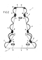
- Figure 4 shows one more metal separator element great length, made according to the same principle, that is to say by the assembly boxes 2 and slides 3, 4 and 5 superimposed.
- This extra element great length for example of the order of twelve meters, results from the union of three successive sections each corresponding to an element 1 (typically four meters long) as previously described, the box 2 terminal of a section being merged with the terminal box of the next stretch.
- the ends of the runners 3, 4 and 5 of a section overlap the ends corresponding slides 3, 4 and 5 of the following section.
- the fixing of ends thus superimposed of the slides 3, 4 and 5, on the common box 2 is also provided jointly, that is to say by the same bolts, as detailed previously with reference to FIG. 2.
Abstract
Description
La présente invention concerne un élément séparateur métallique pour voies de circulation routière, utilisable en particulier comme élément d'une barrière de séparation temporaire, en vue de la délimitation sécurisée d'une zone de chantier routier ou autoroutier, c'est-à-dire de la séparation physique, pendant la durée d'un chantier, entre une ou des voies réservées à la circulation des véhicules, et une ou des autres voies ou une bande de terrain, sur lesquelles sont effectués, des travaux tels que réfection ou élargissement de chaussée.The present invention relates to a metal separating element for traffic lanes, usable in particular as part of a temporary separation barrier, for the secure demarcation of a road or motorway construction site, i.e. physical separation, during the duration of a site, between one or more lanes reserved for vehicle traffic, and one or more other lanes or a strip of land, on which are carried out works such as repair or widening of the road.
Ces éléments séparateurs sont, le plus souvent, réalisés sous la forme de blocs en béton, complétés par quelques parties métalliques principalement destinées à la jonction des éléments séparateurs entre eux - voir par exemple la demande de brevet français n° 2 810 055 au nom du Demandeur, ou la demande de brevet européenne correspondant n° 1 162 315.These separating elements are most often produced under the form of concrete blocks, supplemented by some metallic parts mainly intended for joining the separating elements together - see for example French patent application No. 2,810,055 in the name of Applicant, or the corresponding European patent application No. 1,162,315.
Toutefois, il a déjà été proposé un concept de séparateur modulaire de voies de circulation réalisé entièrement en métal, en particulier en acier. Un tel séparateur comprend des pieds-supports, sur les côtés desquels sont fixées des glissières métalliques, du genre de celles utilisées de façon courante comme glissières de sécurité, installées le long des voies de circulation routière.However, a modular separator concept has already been proposed. of traffic lanes made entirely of metal, in particular steel. A such a separator comprises support legs, on the sides of which are fixed metal slides, such as those commonly used as crash barriers, installed along traffic lanes road.
Dans les réalisations actuellement connues pour ce genre de séparateurs métalliques, la liaison entre deux éléments unitaires consécutifs, placés bout à bout, est réalisée par boulonnage, au moyen de deux, quatre ou six vis, et avec des guides de centrage respectivement mâle et femelle, prévus aux extrémités de ces éléments. Un inconvénient de ce mode de liaison est l'impossibilité de démonter et de retirer un élément séparateur unitaire intercalé dans une file d'éléments, précisément en raison des guides de centrage qui constituent des obstacles à un tel retrait. De plus, le dispositif de liaison par boulonnage nécessite, pour son utilisation, des moyens importants, tant en matériel (fourgon, compresseur, clef à choc, boulonnerie) qu'en main-d'oeuvre (trois personnes étant simultanément nécessaires). Le coût d'exploitation de ces séparateurs métalliques reste donc, actuellement, encore excessivement élevé, ce qui limite fortement leur utilisation. A ceci s'ajoute le fait que les séparateurs métalliques actuels sont aussi d'un prix de revient beaucoup plus élevé que les éléments séparateurs en béton, du seul fait de leur durée de vie plus courte, qui rend nécessaire un renouvellement plus fréquent ; à titre indicatif, la durée de vie moyenne des séparateurs métalliques est de l'ordre de quatre à cinq ans, compte tenu de leur oxydation au contact de l'air et des intempéries, et aussi en raison des chocs et déformations subis lors de leur manutention et de leur utilisation, alors que la durée de vie moyenne d'un élément séparateur en béton peut être estimée à vingt ans.In the realizations currently known for this kind of metal separators, the connection between two consecutive unit elements, placed end to end, is carried out by bolting, using two, four or six screws, and with respectively male and female centering guides, provided at the ends of these elements. One drawback of this connection method is the impossibility of dismantling and removing an interposed unitary separating element in a line of elements, precisely because of the centering guides which are obstacles to such a withdrawal. In addition, the connection device by bolting requires, for its use, significant resources, both in equipment (van, compressor, impact wrench, hardware) as in labor (three people being necessary simultaneously). The operating cost of these metallic separators therefore remain, currently, excessively high, which greatly limits their use. Added to this is the fact that the current metal separators are also much more expensive higher than concrete separating elements, simply because of their service life shorter, which makes more frequent renewal necessary; as indicative, the average lifetime of metallic separators is around four to five years, taking into account their oxidation in contact with air and bad weather, and also because of the shocks and deformations undergone during their handling and their use, while the average lifespan of a concrete separator can be estimated at twenty years.
La présente invention vise à remédier aux inconvénients précités des séparateurs métalliques, et son but est donc de fournir un système de séparateur métallique plus économique, dans sa conception et son exploitation, permettant aussi le retrait et la remise en place aisés d'un élément intercalé dans une file d'éléments.The present invention aims to remedy the aforementioned drawbacks metal separators, and its purpose is therefore to provide a system of more economical metallic separator, in its design and operation, also allowing the easy removal and replacement of an element interspersed in a file of elements.
A cet effet, l'invention a essentiellement pour objet un élément séparateur métallique pour voies de circulation routière, en particulier un élément utilisable pour la délimitation temporaire d'une zone de chantier routier ou autoroutier, cet élément séparateur comprenant de façon généralement connue des supports sur les deux côtés desquels sont fixées des glissières métalliques, et étant caractérisé, selon l'invention, par le fait qu'il comprend deux caissons terminaux, et éventuellement au moins un caisson intermédiaire, constitués chacun par deux joues métalliques parallèles, verticales, reliées l'une à l'autre, sur chaque côté du caisson, par des barres longitudinales qui comportent chacune au moins un trou pour la fixation, par boulonnage, d'au moins une glissière qui relie les caissons.To this end, the subject of the invention is essentially an element metallic separator for traffic lanes, in particular a element usable for the temporary delimitation of a road construction site area or motorway, this separating element generally comprising known supports on both sides of which are fixed slides metallic, and being characterized, according to the invention, by the fact that it comprises two end boxes, and possibly at least one intermediate box, each consisting of two parallel, vertical, connected metal cheeks to each other, on each side of the box, by longitudinal bars which each have at least one hole for fixing, by bolting, of minus a slide that connects the boxes.
Dans une forme de réalisation préférée de l'élément séparateur métallique selon l'invention, les deux joues métalliques de chaque caisson possèdent la forme générale d'un trapèze isocèle, dont la grande base, en position d'utilisation, se situe en bas et sert d'appui au sol pour le caisson. Dans cette configuration, les deux joues métalliques de chaque caisson sont avantageusement raccordées aussi l'une à l'autre, à leurs sommets qui correspondent à la petite base du trapèze, par une plaque métallique supérieure, dont les parties latérales présentent des lumières pour la fixation par boulonnage des glissières supérieures.In a preferred embodiment of the separator element metal according to the invention, the two metal cheeks of each box have the general shape of an isosceles trapezium, the large base of which position of use, is located at the bottom and serves as a floor support for the box. In this configuration, the two metal cheeks of each box are advantageously also connected to each other, at their vertices which correspond to the small base of the trapezoid, by a metal plate upper, whose side parts have lights for fixing by bolting the upper runners.
Dans le détail, selon un mode d'exécution particulier de l'élément séparateur métallique selon l'invention, cet élément séparateur comporte, sur chaque côté, trois glissières superposées reliant ces caissons, avec une glissière inférieure fixée sur une barre longitudinale inférieure, une glissière intermédiaire fixée sur une barre longitudinale intermédiaire, et chevauchant de préférence la glissière inférieure, et une glissière supérieure fixée sur une barre longitudinale supérieure et sur une partie latérale de la plaque métallique supérieure d'un caisson.In detail, according to a particular embodiment of the element metal separator according to the invention, this separating element comprises, on on each side, three superimposed slides connecting these boxes, with a lower slide fixed on a lower longitudinal bar, a slide intermediate fixed on an intermediate longitudinal bar, and overlapping preferably the lower slide, and an upper slide fixed on a bar longitudinal upper and on a lateral part of the metal plate top of a box.
Dans une forme de réalisation préférée de l'élément séparateur métallique objet de l'invention, les deux joues métalliques de ses deux caissons terminaux sont reliées aussi par au moins deux guides tubulaires longitudinaux, servant de logements et de guides de coulissement pour des parties correspondantes d'un dispositif de liaison entre éléments séparateurs consécutifs, mis bout à bout.In a preferred embodiment of the separator element metallic object of the invention, the two metallic cheeks of its two end boxes are also connected by at least two tubular guides longitudinal, serving as housings and sliding guides for corresponding parts of a connecting device between separating elements consecutive, put end to end.
En particulier, le dispositif de liaison, prévu à une extrémité de l'élément séparateur, peut se présenter comme un étrier de liaison comprenant une plaque métallique verticale sur une face de laquelle font saillie des parties horizontales allongées de section et disposition correspondant à celles des guides tubulaires précités, ces parties horizontales étant montées coulissantes dans les guides tubulaires du caisson terminal de l'élément séparateur auquel appartient le dispositif de liaison, et étant engageables dans les guides tubulaires correspondants d'un caisson terminal adjacent, appartenant à un autre élément séparateur à relier au précédent.In particular, the connection device, provided at one end of the separating element, can be presented as a connecting stirrup comprising a vertical metal plate on one side of which project parts elongated horizontal sections and arrangement corresponding to those of aforementioned tubular guides, these horizontal parts being slidably mounted in the tubular guides of the terminal box of the separating element to which belongs the connecting device, and being engaging in the guides corresponding tubulars of an adjacent terminal box, belonging to a another separating element to link to the previous one.
En particulier dans le cas de joues métalliques de forme trapézoïdale, les deux joues des deux caissons terminaux de l'élément séparateur sont avantageusement reliées par trois guides tubulaires longitudinaux, comprenant un guide tubulaire supérieur et deux guides tubulaires inférieurs, disposés suivant les sommets d'un triangle isocèle, la plaque métallique verticale de l'étrier de liaison portant sur l'une de ses faces trois parties longitudinales allongées de disposition correspondant à celle des trois guides tubulaires. Dans la pratique, ces guides tubulaires longitudinaux sont constitués par des tubes métalliques horizontaux, de section rectangulaire, dont les extrémités sont soudées sur le bord d'ouvertures rectangulaires correspondantes, ménagées dans les deux joues de chaque caisson terminal, tandis que les parties correspondantes du dispositif de liaison entre éléments séparateurs sont constituées par des fers plats, chacun de longueur légèrement supérieure au double de la longueur de l'un des tubes précités, les fers plats étant soudés sur une face de la plaque métallique verticale de l'étrier de liaison.Particularly in the case of shaped metal cheeks trapezoidal, the two cheeks of the two terminal boxes of the element separator are advantageously connected by three tubular guides longitudinal, comprising an upper tubular guide and two guides lower tubulars, arranged along the vertices of an isosceles triangle, the vertical metal plate of the connecting bracket bearing on one of its faces three elongated longitudinal parts of arrangement corresponding to that of the three tubular guides. In practice, these longitudinal tubular guides consist of horizontal metal tubes, of section rectangular, the ends of which are welded to the edge of openings corresponding rectangles, arranged in the two cheeks of each terminal box, while the corresponding parts of the connecting device between separating elements are constituted by flat irons, each of length slightly greater than twice the length of one of the tubes mentioned above, the flat bars being welded to one face of the metal plate vertical of the connecting bracket.
Cette plaque métallique verticale porte encore avantageusement une poignée de manoeuvre, sur sa face opposée à celle pourvue des parties horizontales allongées, en particulier constituées par des fers plats. This vertical metal plate still advantageously carries an operating handle, on its face opposite to that provided with the parts horizontal elongated, in particular constituted by flat irons.
Ces parties horizontales allongées sont elles-mêmes avantageusement pourvues chacune, vers leurs extrémités libres, d'une lumière prévue pour recevoir une clavette de verrouillage amovible.These elongated horizontal parts are themselves advantageously each provided, towards their free ends, with a light designed to receive a removable locking key.
L'élément séparateur métallique selon l'invention peut se présenter comme un élément séparateur relativement court, comprenant deux caissons terminaux et un unique caisson intermédiaire, reliés entre eux, sur leurs deux côtés, par des glissières latérales dont la longueur est égale à la longueur totale de l'élément séparateur.The metallic separating element according to the invention can be presented as a relatively short separating element, comprising two boxes terminals and a single intermediate box, connected together, on their two sides, by side rails whose length is equal to the length total of the separating element.
Toutefois, selon une autre possibilité, l'élément séparateur métallique, objet de l'invention, se présente comme un élément séparateur relativement long, comprenant deux caissons terminaux et une pluralité de caissons intermédiaires, reliés entre eux par des glissières latérales successives, de longueur égale environ à un sous-multiple de la longueur totale de l'élément séparateur, les extrémités de ces glissières se superposant au niveau de caissons intermédiaires, sur lesquelles elles sont simultanément fixées par boulonnage.Alternatively, however, the separator element metallic object of the invention is presented as a separating element relatively long, comprising two terminal boxes and a plurality of intermediate boxes, interconnected by side rails successive, of length approximately equal to a submultiple of the length totality of the separating element, the ends of these slides overlapping at the level of intermediate boxes, on which they are simultaneously fixed by bolting.
Dans l'ensemble, l'invention procure ainsi un élément séparateur métallique qui possède des avantages nombreux et particulièrement appréciables :Overall, the invention thus provides a separating element metallic which has numerous advantages and particularly appreciable:
La structure et la fabrication de cet élément séparateur sont simples et par conséquent économiques, en particulier en raison de la constitution des caissons et du dispositif de liaison à partir de tôles découpées, de fers plats et de tubes, les seuls boulons nécessaires étant ceux réalisant la fixation des glissières sur les caissons.The structure and manufacture of this separating element are simple and therefore economical, especially due to the constitution of the boxes and the connection device from cut sheets, flat irons and tubes, the only bolts necessary being those carrying out the fixing of the rails on the boxes.
Le dispositif de liaison entre éléments séparateurs mis bout à bout est lui aussi particulièrement simple, puisqu'il ne nécessite ni boulons, ni organes d'articulation ou analogues.The connecting device between separating elements placed end to end is also particularly simple, since it requires neither bolts nor articulation organs or the like.
Le caractère économique de cet élément séparateur métallique résulte aussi de l'utilisation de glissières métalliques classiques, du commerce, en particulier des glissières métalliques préexistantes, pouvant être récupérées à moindre coût, par exemple lors de leur remplacement par des barrières en béton utilisées comme séparation définitive.The economic nature of this metallic separating element also results from the use of conventional metal slides, from trade, in particular pre-existing metal slides, which can be recovered at lower cost, for example when replacing them with barriers concrete used as final separation.
Les caissons sont particulièrement rigides, ceci s'appliquant en particulier aux caissons terminaux, qui sont encore davantage raidis par les tubes reliant leurs deux joues. The boxes are particularly rigid, this applies in particular to terminal caissons, which are further stiffened by tubes connecting their two cheeks.
Les deux extrémités de l'élément séparateur métallique selon l'invention sont parfaitement lisses, puisqu'il s'agit des joues métalliques extérieures des caissons terminaux, ce qui permet de retirer aisément un élément séparateur inséré dans une file continue d'éléments, et de remettre éventuellement en place cet élément.The two ends of the metal separating element according to the invention are perfectly smooth, since these are metal cheeks exterior of the terminal boxes, which makes it easy to remove a separator element inserted in a continuous line of elements, and to put back possibly in place this element.
L'opération d'assemblage des éléments séparateurs les uns aux autres est particulièrement aisée et rapide. En effet, cette opération ne nécessite aucun boulonnage, et grâce au dispositif à étrier, tous les fers plats de liaison, qui forment en quelque sorte des éclisses, sont coulissés simultanément dans les tubes de guidage correspondants, avec un faible effort manuel. Il en est évidemment de même pour l'opération inverse de séparation de deux éléments. Ces opérations peuvent donc être réalisées sans difficulté par une seule personne, ce qui entraíne aussi une forte économie de main-d'oeuvre.The operation of assembling the separating elements together others are particularly easy and fast. This operation does not requires no bolting, and thanks to the clamping device, all flat irons links, which in a way form fishplates, are slid simultaneously in the corresponding guide tubes, with low effort manual. It is obviously the same for the reverse separation operation of two elements. These operations can therefore be carried out without difficulty by one person, which also results in a significant saving in labor.
De plus, l'assemblage ainsi réalisé entre deux éléments séparateurs consécutifs est particulièrement rigide, et il est sécurisé par les clavettes de verrouillage.In addition, the assembly thus produced between two elements consecutive dividers is particularly rigid, and it is secured by locking keys.
Grâce à la conception de séparateur selon l'invention, il est notamment possible de constituer des éléments séparateurs métalliques "courts", typiquement d'une longueur de quatre mètres, avec deux caissons terminaux et un seul caisson intermédiaire, qui réalisent un "module" équivalent à un séparateur standard en béton.Thanks to the separator design according to the invention, it is in particular possible to constitute metallic separating elements "short", typically four meters long, with two boxes terminals and a single intermediate box, which produce an equivalent "module" to a standard concrete separator.
Cependant, l'invention permet aussi la constitution d'éléments séparateurs métalliques "longs", typiquement d'une longueur de douze mètres environ, avec des caissons intermédiaires plus nombreux et des glissières chevauchantes, de tels éléments étant transportables sur un ensemble routier à tracteur et semi-remorque avec grue de manutention, et leur plus grande longueur permettant de réduire le nombre d'opérations d'assemblage entre éléments (pour une longueur totale donnée de la barrière à réaliser).However, the invention also allows the constitution of elements "long" metal separators, typically twelve meters long approx., with more intermediate boxes and slides overlapping, such elements being transportable on a road assembly with tractor and semi-trailer with handling crane, and their larger length to reduce the number of assembly operations between elements (for a given total length of the barrier to be produced).
L'invention sera mieux comprise à l'aide de la description qui suit,
en référence au dessin schématique annexé représentant, à titre d'exemples,
deux formes d'exécution de cet élément séparateur métallique :
Sur les figures 1 à 3, un élément séparateur métallique est désigné
globalement pour le repère 1. Cet élément, par exemple d'une longueur de
quatre mètres, est constitué par trois caissons 2, comprenant deux caissons
terminaux et un caisson intermédiaire, reliés entre eux par des glissières
latérales 3, 4 et 5 dont ils constituent le support.In Figures 1 to 3, a metal separator element is designated
overall for the reference 1. This element, for example with a length of
four meters, consists of three
En se référant plus particulièrement aux figures 1 et 2, on décrira
tout d'abord le détail d'un caisson 2.With particular reference to Figures 1 and 2, we will describe
first of all the detail of a
Le caisson 2 comprend deux joues verticales parallèles 6,
constituées par des tôles métalliques découpées en forme générale de trapèze
isocèle, dont la grande base se situe en bas (au niveau du sol, lors de
l'utilisation de l'élément séparateur 1).The
Les deux joues verticales 6 du caisson 7 sont reliées l'une à l'autre
horizontalement, sur chaque côté du caisson 2, par trois fers plats
superposés 7, 8 et 9, dont les extrémités sont soudées aux bords inclinés des
joues 6. Chaque fer plat 7, 8 et 9 comporte, à mi-longueur, un trou 10 pour la
fixation des glissières, comme précisé ci-après.The two
De plus, les sommets respectifs des deux joues verticales 6, qui
correspondent à la petite base du trapèze, sont raccordés l'un à l'autre par une
plaque supérieure 11 en tôle, dont la partie médiane horizontale peut
comporter une large ouverture rectangulaire 12, et dont les parties latérales,
inclinées symétriquement, présentent chacune deux lumières 13.In addition, the respective vertices of the two
Les deux joues verticales 6 sont encore reliées l'une à l'autre par
trois tubes métalliques horizontaux, de section rectangulaire, soit un tube
supérieur 14 et deux tubes inférieurs 15, disposés suivant les sommets d'un
triangle isocèle. Les extrémités de ces tubes 14 et 15 sont soudées sur le bord
d'ouvertures rectangulaires correspondantes, ménagées dans les deux
joues 6.The two
Chaque caisson 2, ainsi constitué, forme un bloc rigide, apte à
reposer sur le soi par les grandes bases de ses deux joues 6 trapézoïdales.Each
Les caissons 2 sont reliés entre eux par les glissières 3, 4 et 5,
fixées au moyen de boulons 16. Comme le montre plus particulièrement la
figure 2, les deux glissières inférieures 3 sont fixées symétriquement sur les
fers plats inférieurs 7, au moyen de boulons 16 qui traversent les trous 10 de
ces fers plats 7. Les deux glissières intermédiaires 4 sont fixées
symétriquement sur les fers plats intermédiaires 8, au moyen de boulons 16 qui
traversent les trous 10 de ces fers plats 8, la partie inférieure de chaque
glissière intermédiaire 4 venant chevaucher la partie supérieure de la glissière
inférieure 3 correspondante. Enfin, les deux glissières supérieures 5 sont fixées
symétriquement, d'une part, sur les fers plats supérieurs 9, au moyen de
boulons 16 qui traversent les trous 10 de ces fers plats 9, et d'autre part, sur
les parties latérales inclinées de la tôle supérieure 11, au moyen de boulons 16
qui traversent les lumières 13 de ces parties latérales. En fixant ainsi les
glissières 3, 4 et 5, toutes de même longueur (notamment de quatre mètres),
sur deux caissons 2 terminaux et sur un caisson 2 intermédiaire, il est constitué
un élément séparateur métallique 1, de structure rigide, pourvu sur chaque
côté de trois glissières superposées 3, 4 et 5.The
L'élément séparateur 1 est pourvu, à une extrémité, d'un étrier
coulissant 17 de liaison avec un autre élément séparateur 1, les deux éléments
séparateurs 1 étant placés bout à bout, comme illustré par les figures 1 et 3.
L'étrier 17, bien visible sur la figure 1, comprend une plaque métallique
verticale 18, de forme trapézoïdale ou triangulaire, sur une face de laquelle
sont soudés trois fers plats parallèles et horizontaux, comprenant un fer plat
supérieur 19 et deux fers plats inférieurs 20, dont la disposition correspond à
celle des trois tubes 14, 15 de section rectangulaire d'un caisson 2. Chaque
fer plat 19 ou 20 possède une longueur légèrement supérieure au double de la
longueur d'un tube 14 ou 15. Vers son extrémité libre, chaque fer plat 19 ou 20
possède une lumière ou fente 21, prévue pour recevoir une clavette de
verrouillage amovible 22. Sur sa face opposée aux fers plats 19 et 20, la
plaque métallique 18 de l'étrier 17 porte une poignée de manoeuvre 23.The separating element 1 is provided, at one end, with a stirrup
sliding 17 connecting with another separating element 1, the two elements
separators 1 being placed end to end, as illustrated in Figures 1 and 3.
The
Un tel étrier 17 est mis en place à une extrémité de chaque
élément séparateur 1, sur le caisson terminal 2. Les fers plats 19 et 20 de
l'étrier sont engagés de façon coulissante dans les tubes 14 et 15 de ce
caisson terminal 2, de telle sorte que les extrémités des fers plats 19 et 20 font
saillie à l'extrémité considérée de l'élément séparateur 1. L'ensemble de
l'étrier 17 est ainsi déplaçable en translation, dans la direction longitudinale de
l'élément séparateur 1, suivant la double flèche F de la figure 1.Such a
Lorsque deux éléments séparateurs 1 sont mis bout à bout, comme
le suggère la figure 1 et comme le montre la figure 3 à droite, l'étrier 17 d'un
premier élément 1, manoeuvré par sa poignée 23, est avancé vers l'extrémité
d'un second élément 1, non pourvue d'étrier. Les fers plats 19 et 20 de
l'étrier 17, coulissants dans les tubes 14 et 15 du caisson 2 terminal du premier
élément 1, sont ainsi engagés aussi dans les tubes 14 et 15 du caisson 2
terminal du second élément 1. Les extrémités libres des fers plats 19 et 20, qui
finalement dépassent hors des tubes 14 et 15 du caisson 2 terminal du second
élément 1, reçoivent enfin des clavettes 22, ce qui verrouille l'assemblage des
deux éléments séparateurs 1.When two separating elements 1 are placed end to end, as
suggests it in figure 1 and as shown in figure 3 on the right, the
Cet assemblage reste démontable, en retirant les clavettes de
verrouillage 22, puis en faisant reculer l'étrier 17, toujours en le manoeuvrant
par sa poignée 23.This assembly remains removable, by removing the keys from
locking 22, then moving the
Comme on le comprend aisément, un élément séparateur 1 intercalé dans une file continue de tels éléments séparateurs peut, de cette manière, être retiré de la file d'éléments, et être éventuellement remis en place, sans déplacer les autres éléments séparateurs de cette file.As is easily understood, a separating element 1 interspersed in a continuous line with such separating elements can, from this way, be removed from the line of items, and possibly be replaced, without moving the other separating elements of this queue.
La figure 4 représente un élément séparateur métallique de plus
grande longueur, réalisé selon le même principe, c'est-à-dire par l'assemblage
de caissons 2 et de glissières 3, 4 et 5 superposées. Cet élément de plus
grande longueur, par exemple de l'ordre de douze mètres, résulte de la réunion
de trois tronçons successifs correspondant chacun à un élément 1
(typiquement d'une longueur de quatre mètres) tel que précédemment décrit, le
caisson 2 terminal d'un tronçon étant confondu avec le caisson terminal du
tronçon suivant. Au niveau d'un tel caisson 2 commun, les extrémités des
glissières 3, 4 et 5 d'un tronçon viennent chevaucher les extrémités
correspondantes des glissières 3, 4 et 5 du tronçon suivant. La fixation des
extrémités ainsi superposées des glissières 3, 4 et 5, sur le caisson 2 commun,
est assurée elle aussi de façon commune, c'est-à-dire par les mêmes boulons,
de la manière détaillée précédemment en référence à la figure 2.Figure 4 shows one more metal separator element
great length, made according to the same principle, that is to say by the
Il est ainsi possible de constituer des éléments séparateurs d'une
longueur de l'ordre de douze mètres, transportables sur une semi-remorque
routière. Ces éléments séparateurs "longs" peuvent être eux-mêmes disposés
en file, et assemblés entre eux par le dispositif de liaison à étrier 17 qui est
encore prévu à l'une de leurs extrémités, de la manière précédemment décrite.It is thus possible to constitute separating elements of a
length of the order of twelve meters, transportable on a semi-trailer
road. These "long" separating elements can themselves be arranged
in file, and assembled together by the
L'on ne s'éloignerait pas du cadre de l'invention, telle que définie dans les revendications annexées, quels que soient notamment :
- les formes de détail des caissons, en particulier le contour de leurs joues ;
- le détail des moyens d'assemblage entre éléments séparateurs ;
- la longueur de ces éléments séparateurs, et le nombre des caissons intermédiaires, choisi en fonction de cette longueur
- the detail forms of the boxes, in particular the outline of their cheeks;
- details of the assembly means between separating elements;
- the length of these separating elements, and the number of intermediate boxes, chosen according to this length
Claims (12)
Applications Claiming Priority (2)
| Application Number | Priority Date | Filing Date | Title |
|---|---|---|---|
| FR0302875 | 2003-03-07 | ||
| FR0302875A FR2852035B1 (en) | 2003-03-07 | 2003-03-07 | MATERIAL SEPARATOR ELEMENT FOR ROAD TRAFFIC PATHS |
Publications (2)
| Publication Number | Publication Date |
|---|---|
| EP1455021A1 true EP1455021A1 (en) | 2004-09-08 |
| EP1455021B1 EP1455021B1 (en) | 2007-04-18 |
Family
ID=32799653
Family Applications (1)
| Application Number | Title | Priority Date | Filing Date |
|---|---|---|---|
| EP04356024A Expired - Lifetime EP1455021B1 (en) | 2003-03-07 | 2004-02-25 | Metal separator element for traffic lanes |
Country Status (5)
| Country | Link |
|---|---|
| EP (1) | EP1455021B1 (en) |
| AT (1) | ATE360117T1 (en) |
| DE (1) | DE602004005907T2 (en) |
| ES (1) | ES2286575T3 (en) |
| FR (1) | FR2852035B1 (en) |
Cited By (2)
| Publication number | Priority date | Publication date | Assignee | Title |
|---|---|---|---|---|
| FR3029220A1 (en) * | 2014-12-02 | 2016-06-03 | Aximum | MODULAR METAL RETENTION DEVICE FOR ROADWAYS, MODULE AND METHOD OF INSTALLATION |
| US9822548B1 (en) * | 2017-02-08 | 2017-11-21 | John Harkins | Barrier wall system and method |
Citations (6)
| Publication number | Priority date | Publication date | Assignee | Title |
|---|---|---|---|---|
| NL9101214A (en) * | 1991-07-10 | 1993-02-01 | Prins Dokkum B V | Fence, and clamp for use therewith |
| US5531540A (en) * | 1995-01-13 | 1996-07-02 | Yew Corporation | Reinforcement system for highway barriers |
| DE19735507C1 (en) * | 1997-08-16 | 1998-11-12 | Spig Schutzplanken Prod Gmbh | Roadway protective crash-barrier for vehicles |
| FR2788068A1 (en) * | 1999-01-05 | 2000-07-07 | Claude Alix Georges Pomero | Road safety barrier has posts with blocks having faces to support rails and infill to absorb shocks |
| EP1162315A1 (en) | 2000-06-08 | 2001-12-12 | Balisage-Securité-Service- B.S.S. | Concrete safety-barrier for roads |
| EP1285999A2 (en) * | 2001-08-22 | 2003-02-26 | Sps Schutzplanken Gmbh | Guard rail |
-
2003
- 2003-03-07 FR FR0302875A patent/FR2852035B1/en not_active Expired - Fee Related
-
2004
- 2004-02-25 AT AT04356024T patent/ATE360117T1/en not_active IP Right Cessation
- 2004-02-25 EP EP04356024A patent/EP1455021B1/en not_active Expired - Lifetime
- 2004-02-25 ES ES04356024T patent/ES2286575T3/en not_active Expired - Lifetime
- 2004-02-25 DE DE602004005907T patent/DE602004005907T2/en not_active Expired - Lifetime
Patent Citations (7)
| Publication number | Priority date | Publication date | Assignee | Title |
|---|---|---|---|---|
| NL9101214A (en) * | 1991-07-10 | 1993-02-01 | Prins Dokkum B V | Fence, and clamp for use therewith |
| US5531540A (en) * | 1995-01-13 | 1996-07-02 | Yew Corporation | Reinforcement system for highway barriers |
| DE19735507C1 (en) * | 1997-08-16 | 1998-11-12 | Spig Schutzplanken Prod Gmbh | Roadway protective crash-barrier for vehicles |
| FR2788068A1 (en) * | 1999-01-05 | 2000-07-07 | Claude Alix Georges Pomero | Road safety barrier has posts with blocks having faces to support rails and infill to absorb shocks |
| EP1162315A1 (en) | 2000-06-08 | 2001-12-12 | Balisage-Securité-Service- B.S.S. | Concrete safety-barrier for roads |
| FR2810055A1 (en) | 2000-06-08 | 2001-12-14 | Balisage Securite Service B S | CONCRETE SAFETY BARRIER FOR HIGHWAYS AND HIGHWAYS |
| EP1285999A2 (en) * | 2001-08-22 | 2003-02-26 | Sps Schutzplanken Gmbh | Guard rail |
Cited By (3)
| Publication number | Priority date | Publication date | Assignee | Title |
|---|---|---|---|---|
| FR3029220A1 (en) * | 2014-12-02 | 2016-06-03 | Aximum | MODULAR METAL RETENTION DEVICE FOR ROADWAYS, MODULE AND METHOD OF INSTALLATION |
| EP3029202A1 (en) * | 2014-12-02 | 2016-06-08 | Aximum | Modular metallic retaining device for roadways, module and installation method |
| US9822548B1 (en) * | 2017-02-08 | 2017-11-21 | John Harkins | Barrier wall system and method |
Also Published As
| Publication number | Publication date |
|---|---|
| EP1455021B1 (en) | 2007-04-18 |
| FR2852035B1 (en) | 2005-05-27 |
| DE602004005907T2 (en) | 2008-01-17 |
| DE602004005907D1 (en) | 2007-05-31 |
| ES2286575T3 (en) | 2007-12-01 |
| FR2852035A1 (en) | 2004-09-10 |
| ATE360117T1 (en) | 2007-05-15 |
Similar Documents
| Publication | Publication Date | Title |
|---|---|---|
| EP0278881A2 (en) | Arch-shaped structure for snow protection | |
| EP1101871A1 (en) | Steel bridge deck and method for the construction of a bridge with such a deck | |
| EP1561708B1 (en) | Demountable modular platform for a refuse dump | |
| FR2810055A1 (en) | CONCRETE SAFETY BARRIER FOR HIGHWAYS AND HIGHWAYS | |
| FR2950906A1 (en) | DEVICE FOR CONNECTION BETWEEN TWO PREFABRICATED FLAT ELEMENTS ASSEMBLED IN LINEAR SUCCESSION AND SUBSTANTIALLY COPLANAR | |
| FR2548637A1 (en) | GUTTER SECTION FOR A SQUEEGEE CONVEYOR, TO BE USED IN PARTICULAR IN MINING OPERATIONS | |
| CH616197A5 (en) | ||
| EP1455021B1 (en) | Metal separator element for traffic lanes | |
| FR2897604A1 (en) | Plastic film installing device for use on greenhouse framework, has inverted U-shaped portico extending in vertical plane, where portico includes bearings for receiving and positioning roller of plastic film in horizontal position | |
| EP0844335A1 (en) | Movable barrier and assembly formed by a set of such barriers | |
| FR2898374A1 (en) | Stage floor module for e.g. road show, has spacing and connection parts connecting base subassemblies, where subassemblies are assembled with spacing and connection parts at level of posts with integration sites | |
| FR2903709A1 (en) | Separation barriers installing/manipulating/retracting equipment for e.g. separating construction site from motorway`s path, has carriage with holes and bolts to fix carriage to side of cage, and wheels displaced on top of barrier elements | |
| FR2660676A1 (en) | SLIDE WITH DOUBLE SLIDING ELEMENT FOR RETAINING VEHICLES ON A ROAD. | |
| EP1182296A1 (en) | Road safety barrier | |
| EP1001090A2 (en) | Movable barriers elements | |
| FR2669834A1 (en) | Removable guard rail for ice (skating) rink | |
| WO2002035006A1 (en) | Module for modular bridge and method for mounting such a bridge | |
| FR2645186A1 (en) | Warning sign support | |
| FR2815980A1 (en) | Assembly method for metal frame | |
| FR2576355A1 (en) | Formwork for building tunnels | |
| EP1541769A1 (en) | Road safety guardrail with protection screen composed of a longitudinal reinforced member and a sliding element | |
| FR2922232A1 (en) | ELEMENT FOR ATTACHING A SLIDE OF A SAFETY SLIDE TO A SUPPORT | |
| EP0692350A1 (en) | Modular assembly plate for shaping curved laminated beams | |
| FR2927831A1 (en) | Work line constituting method for motor vehicle piece assembling chain, involves forming adjacent work zones with respective heights defined by stack of base elements for constituting work line adapted to variations of assembling conditions | |
| FR2517608A1 (en) | Framework for vehicle canopy - includes bars carrying end blocks which locate into brackets on adjacent cross members |
Legal Events
| Date | Code | Title | Description |
|---|---|---|---|
| PUAI | Public reference made under article 153(3) epc to a published international application that has entered the european phase |
Free format text: ORIGINAL CODE: 0009012 |
|
| AK | Designated contracting states |
Kind code of ref document: A1 Designated state(s): AT BE BG CH CY CZ DE DK EE ES FI FR GB GR HU IE IT LI LU MC NL PT RO SE SI SK TR |
|
| AX | Request for extension of the european patent |
Extension state: AL HR LT LV MK |
|
| 17P | Request for examination filed |
Effective date: 20050304 |
|
| AKX | Designation fees paid |
Designated state(s): AT BE BG CH CY CZ DE DK EE ES FI FR GB GR HU IE IT LI LU MC NL PT RO SE SI SK TR |
|
| GRAP | Despatch of communication of intention to grant a patent |
Free format text: ORIGINAL CODE: EPIDOSNIGR1 |
|
| GRAS | Grant fee paid |
Free format text: ORIGINAL CODE: EPIDOSNIGR3 |
|
| GRAA | (expected) grant |
Free format text: ORIGINAL CODE: 0009210 |
|
| AK | Designated contracting states |
Kind code of ref document: B1 Designated state(s): AT BE BG CH CY CZ DE DK EE ES FI FR GB GR HU IE IT LI LU MC NL PT RO SE SI SK TR |
|
| PG25 | Lapsed in a contracting state [announced via postgrant information from national office to epo] |
Ref country code: FI Free format text: LAPSE BECAUSE OF FAILURE TO SUBMIT A TRANSLATION OF THE DESCRIPTION OR TO PAY THE FEE WITHIN THE PRESCRIBED TIME-LIMIT Effective date: 20070418 Ref country code: SI Free format text: LAPSE BECAUSE OF FAILURE TO SUBMIT A TRANSLATION OF THE DESCRIPTION OR TO PAY THE FEE WITHIN THE PRESCRIBED TIME-LIMIT Effective date: 20070418 |
|
| REG | Reference to a national code |
Ref country code: CH Ref legal event code: EP |
|
| REG | Reference to a national code |
Ref country code: IE Ref legal event code: FG4D Free format text: LANGUAGE OF EP DOCUMENT: FRENCH |
|
| REF | Corresponds to: |
Ref document number: 602004005907 Country of ref document: DE Date of ref document: 20070531 Kind code of ref document: P |
|
| PG25 | Lapsed in a contracting state [announced via postgrant information from national office to epo] |
Ref country code: SE Free format text: LAPSE BECAUSE OF FAILURE TO SUBMIT A TRANSLATION OF THE DESCRIPTION OR TO PAY THE FEE WITHIN THE PRESCRIBED TIME-LIMIT Effective date: 20070718 |
|
| GBT | Gb: translation of ep patent filed (gb section 77(6)(a)/1977) |
Effective date: 20070726 |
|
| PG25 | Lapsed in a contracting state [announced via postgrant information from national office to epo] |
Ref country code: PT Free format text: LAPSE BECAUSE OF FAILURE TO SUBMIT A TRANSLATION OF THE DESCRIPTION OR TO PAY THE FEE WITHIN THE PRESCRIBED TIME-LIMIT Effective date: 20070918 |
|
| PG25 | Lapsed in a contracting state [announced via postgrant information from national office to epo] |
Ref country code: AT Free format text: LAPSE BECAUSE OF FAILURE TO SUBMIT A TRANSLATION OF THE DESCRIPTION OR TO PAY THE FEE WITHIN THE PRESCRIBED TIME-LIMIT Effective date: 20070418 |
|
| REG | Reference to a national code |
Ref country code: ES Ref legal event code: FG2A Ref document number: 2286575 Country of ref document: ES Kind code of ref document: T3 |
|
| PG25 | Lapsed in a contracting state [announced via postgrant information from national office to epo] |
Ref country code: DK Free format text: LAPSE BECAUSE OF FAILURE TO SUBMIT A TRANSLATION OF THE DESCRIPTION OR TO PAY THE FEE WITHIN THE PRESCRIBED TIME-LIMIT Effective date: 20070418 Ref country code: CZ Free format text: LAPSE BECAUSE OF FAILURE TO SUBMIT A TRANSLATION OF THE DESCRIPTION OR TO PAY THE FEE WITHIN THE PRESCRIBED TIME-LIMIT Effective date: 20070418 Ref country code: BG Free format text: LAPSE BECAUSE OF FAILURE TO SUBMIT A TRANSLATION OF THE DESCRIPTION OR TO PAY THE FEE WITHIN THE PRESCRIBED TIME-LIMIT Effective date: 20070718 |
|
| PLBE | No opposition filed within time limit |
Free format text: ORIGINAL CODE: 0009261 |
|
| STAA | Information on the status of an ep patent application or granted ep patent |
Free format text: STATUS: NO OPPOSITION FILED WITHIN TIME LIMIT |
|
| PG25 | Lapsed in a contracting state [announced via postgrant information from national office to epo] |
Ref country code: SK Free format text: LAPSE BECAUSE OF FAILURE TO SUBMIT A TRANSLATION OF THE DESCRIPTION OR TO PAY THE FEE WITHIN THE PRESCRIBED TIME-LIMIT Effective date: 20070418 |
|
| 26N | No opposition filed |
Effective date: 20080121 |
|
| REG | Reference to a national code |
Ref country code: HU Ref legal event code: AG4A Ref document number: E002458 Country of ref document: HU |
|
| PG25 | Lapsed in a contracting state [announced via postgrant information from national office to epo] |
Ref country code: GR Free format text: LAPSE BECAUSE OF FAILURE TO SUBMIT A TRANSLATION OF THE DESCRIPTION OR TO PAY THE FEE WITHIN THE PRESCRIBED TIME-LIMIT Effective date: 20070719 |
|
| PG25 | Lapsed in a contracting state [announced via postgrant information from national office to epo] |
Ref country code: RO Free format text: LAPSE BECAUSE OF FAILURE TO SUBMIT A TRANSLATION OF THE DESCRIPTION OR TO PAY THE FEE WITHIN THE PRESCRIBED TIME-LIMIT Effective date: 20070418 |
|
| PG25 | Lapsed in a contracting state [announced via postgrant information from national office to epo] |
Ref country code: MC Free format text: LAPSE BECAUSE OF NON-PAYMENT OF DUE FEES Effective date: 20080228 |
|
| PG25 | Lapsed in a contracting state [announced via postgrant information from national office to epo] |
Ref country code: EE Free format text: LAPSE BECAUSE OF FAILURE TO SUBMIT A TRANSLATION OF THE DESCRIPTION OR TO PAY THE FEE WITHIN THE PRESCRIBED TIME-LIMIT Effective date: 20070418 |
|
| PG25 | Lapsed in a contracting state [announced via postgrant information from national office to epo] |
Ref country code: CY Free format text: LAPSE BECAUSE OF FAILURE TO SUBMIT A TRANSLATION OF THE DESCRIPTION OR TO PAY THE FEE WITHIN THE PRESCRIBED TIME-LIMIT Effective date: 20070418 |
|
| PG25 | Lapsed in a contracting state [announced via postgrant information from national office to epo] |
Ref country code: TR Free format text: LAPSE BECAUSE OF FAILURE TO SUBMIT A TRANSLATION OF THE DESCRIPTION OR TO PAY THE FEE WITHIN THE PRESCRIBED TIME-LIMIT Effective date: 20070418 |
|
| REG | Reference to a national code |
Ref country code: FR Ref legal event code: PLFP Year of fee payment: 13 |
|
| REG | Reference to a national code |
Ref country code: FR Ref legal event code: PLFP Year of fee payment: 14 |
|
| REG | Reference to a national code |
Ref country code: FR Ref legal event code: PLFP Year of fee payment: 15 |
|
| PGFP | Annual fee paid to national office [announced via postgrant information from national office to epo] |
Ref country code: LU Payment date: 20210114 Year of fee payment: 18 |
|
| PGFP | Annual fee paid to national office [announced via postgrant information from national office to epo] |
Ref country code: NL Payment date: 20210129 Year of fee payment: 18 Ref country code: FR Payment date: 20210129 Year of fee payment: 18 Ref country code: CH Payment date: 20210129 Year of fee payment: 18 Ref country code: IE Payment date: 20210118 Year of fee payment: 18 Ref country code: IT Payment date: 20210209 Year of fee payment: 18 |
|
| PGFP | Annual fee paid to national office [announced via postgrant information from national office to epo] |
Ref country code: GB Payment date: 20210205 Year of fee payment: 18 Ref country code: ES Payment date: 20210305 Year of fee payment: 18 Ref country code: BE Payment date: 20210212 Year of fee payment: 18 Ref country code: HU Payment date: 20210126 Year of fee payment: 18 Ref country code: DE Payment date: 20210129 Year of fee payment: 18 |
|
| REG | Reference to a national code |
Ref country code: DE Ref legal event code: R119 Ref document number: 602004005907 Country of ref document: DE |
|
| REG | Reference to a national code |
Ref country code: NL Ref legal event code: MM Effective date: 20220301 |
|
| REG | Reference to a national code |
Ref country code: CH Ref legal event code: PL |
|
| REG | Reference to a national code |
Ref country code: BE Ref legal event code: MM Effective date: 20220228 |
|
| GBPC | Gb: european patent ceased through non-payment of renewal fee |
Effective date: 20220225 |
|
| PG25 | Lapsed in a contracting state [announced via postgrant information from national office to epo] |
Ref country code: LU Free format text: LAPSE BECAUSE OF NON-PAYMENT OF DUE FEES Effective date: 20220225 |
|
| PG25 | Lapsed in a contracting state [announced via postgrant information from national office to epo] |
Ref country code: HU Free format text: LAPSE BECAUSE OF NON-PAYMENT OF DUE FEES Effective date: 20220226 |
|
| PG25 | Lapsed in a contracting state [announced via postgrant information from national office to epo] |
Ref country code: NL Free format text: LAPSE BECAUSE OF NON-PAYMENT OF DUE FEES Effective date: 20220301 Ref country code: FR Free format text: LAPSE BECAUSE OF NON-PAYMENT OF DUE FEES Effective date: 20220228 |
|
| PG25 | Lapsed in a contracting state [announced via postgrant information from national office to epo] |
Ref country code: LI Free format text: LAPSE BECAUSE OF NON-PAYMENT OF DUE FEES Effective date: 20220228 Ref country code: IE Free format text: LAPSE BECAUSE OF NON-PAYMENT OF DUE FEES Effective date: 20220225 Ref country code: GB Free format text: LAPSE BECAUSE OF NON-PAYMENT OF DUE FEES Effective date: 20220225 Ref country code: DE Free format text: LAPSE BECAUSE OF NON-PAYMENT OF DUE FEES Effective date: 20220901 Ref country code: CH Free format text: LAPSE BECAUSE OF NON-PAYMENT OF DUE FEES Effective date: 20220228 |
|
| PG25 | Lapsed in a contracting state [announced via postgrant information from national office to epo] |
Ref country code: BE Free format text: LAPSE BECAUSE OF NON-PAYMENT OF DUE FEES Effective date: 20220228 |
|
| REG | Reference to a national code |
Ref country code: ES Ref legal event code: FD2A Effective date: 20230331 |
|
| PG25 | Lapsed in a contracting state [announced via postgrant information from national office to epo] |
Ref country code: ES Free format text: LAPSE BECAUSE OF NON-PAYMENT OF DUE FEES Effective date: 20220226 |
|
| PG25 | Lapsed in a contracting state [announced via postgrant information from national office to epo] |
Ref country code: IT Free format text: LAPSE BECAUSE OF NON-PAYMENT OF DUE FEES Effective date: 20220225 |