EP1162315A1 - Concrete safety-barrier for roads - Google Patents
Concrete safety-barrier for roads Download PDFInfo
- Publication number
- EP1162315A1 EP1162315A1 EP01420120A EP01420120A EP1162315A1 EP 1162315 A1 EP1162315 A1 EP 1162315A1 EP 01420120 A EP01420120 A EP 01420120A EP 01420120 A EP01420120 A EP 01420120A EP 1162315 A1 EP1162315 A1 EP 1162315A1
- Authority
- EP
- European Patent Office
- Prior art keywords
- barrier
- elements
- safety
- barrier elements
- covers
- Prior art date
- Legal status (The legal status is an assumption and is not a legal conclusion. Google has not performed a legal analysis and makes no representation as to the accuracy of the status listed.)
- Withdrawn
Links
Images

Classifications
-
- E—FIXED CONSTRUCTIONS
- E01—CONSTRUCTION OF ROADS, RAILWAYS, OR BRIDGES
- E01F—ADDITIONAL WORK, SUCH AS EQUIPPING ROADS OR THE CONSTRUCTION OF PLATFORMS, HELICOPTER LANDING STAGES, SIGNS, SNOW FENCES, OR THE LIKE
- E01F15/00—Safety arrangements for slowing, redirecting or stopping errant vehicles, e.g. guard posts or bollards; Arrangements for reducing damage to roadside structures due to vehicular impact
- E01F15/02—Continuous barriers extending along roads or between traffic lanes
- E01F15/08—Continuous barriers extending along roads or between traffic lanes essentially made of walls or wall-like elements ; Cable-linked blocks
- E01F15/088—Details of element connection
-
- E—FIXED CONSTRUCTIONS
- E01—CONSTRUCTION OF ROADS, RAILWAYS, OR BRIDGES
- E01F—ADDITIONAL WORK, SUCH AS EQUIPPING ROADS OR THE CONSTRUCTION OF PLATFORMS, HELICOPTER LANDING STAGES, SIGNS, SNOW FENCES, OR THE LIKE
- E01F15/00—Safety arrangements for slowing, redirecting or stopping errant vehicles, e.g. guard posts or bollards; Arrangements for reducing damage to roadside structures due to vehicular impact
- E01F15/02—Continuous barriers extending along roads or between traffic lanes
- E01F15/08—Continuous barriers extending along roads or between traffic lanes essentially made of walls or wall-like elements ; Cable-linked blocks
- E01F15/081—Continuous barriers extending along roads or between traffic lanes essentially made of walls or wall-like elements ; Cable-linked blocks characterised by the use of a specific material
- E01F15/083—Continuous barriers extending along roads or between traffic lanes essentially made of walls or wall-like elements ; Cable-linked blocks characterised by the use of a specific material using concrete
Definitions
- the present invention relates to a safety barrier made of concrete, for road and motorway traffic lanes, the barrier being made up of precast concrete elements to be placed on the ground one after the other, and means being provided to ensure the connection between consecutive barrier elements.
- This security barrier may constitute a temporary separation of tracks, in a sector where are carried out work such as repairing or widening the road; she can also constitute a definitive, albeit mobile, separation between two lanes.
- Safety barriers of this kind are currently well known, and commonly used. They usually consist of reinforced concrete elements of length equal for example to about 4 meters, and of standardized profile, widened at its base. These barrier elements are provided, at their ends, with horizontal metal rings at the through which vertical metal rods are introduced, which provide the link between consecutive elements.
- the vertical rods constitute here articulation axes, which allow a certain misalignment between consecutive elements to allow the barrier to follow a line curve, but which affect the rigidity of the connection between the elements of barrier, whereas this rigidity constitutes an essential factor for the effectiveness of the barrier in the event of a vehicle impact.
- French Patent No. 2,749,329 describes already an improved concrete safety barrier, which can be used either as temporary separation or as final separation, thanks to posts inserted through the rings of the barrier elements in concrete, these posts ensuring the connection of two barrier elements consecutive, and simultaneously their anchoring to the ground.
- the rigidity of the connection between consecutive barrier elements is only improved here insofar as the connecting posts are anchored to the ground, either by direct insertion, either by introduction into special plates anchor, themselves fixed to the ground.
- the present invention aims to eliminate the drawbacks previously exposed, providing an improved safety barrier from the point of view of the rigidity of the connection between elements, without necessity ground anchor, and while increasing the maneuverability and safety of this barrier.
- the invention essentially relates to a barrier of concrete safety, of the kind considered here, with means of connection between consecutive barrier elements, comprising metal rings of connection anchored at the ends of said barrier elements, and of the rods bond introduced vertically through the rings, this barrier of security being characterized in that, in particular for the constitution a definitive but mobile barrier, the means of connection between elements barriers still include lower metal covers which take place at the junction of two consecutive barrier elements, in recesses formed under the enlarged base of these elements, each cover lower with a central hole of vertical axis, while the rods of connection are screw-shaped, with a head capable of bearing on one connecting rings, and a threaded part intended to be introduced and screwed into the central hole of a lower cover.
- the connecting means between barrier elements also include covers inverted U-shaped section superiors, designed to overlap the vertices of two consecutive barrier elements, at the junction of these elements, means being provided for the removable lateral fixing of the upper covers on the barrier elements.
- the recesses, formed under the enlarged base of the elements of barrier to receive the lower covers, are advantageously continuous longitudinal recesses, extending over the entire length of these barrier elements.
- the barrier elements also have longitudinal safety grooves for handling, formed on either side of their narrow upper part, these grooves being extended upwards, at both ends of the elements of barrier, by hollowed out parts receiving the upper covers.
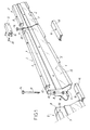
- the safety barrier shown in the drawing, consists of mainly prefabricated barrier elements 2, in reinforced concrete, of which one is fully visible in Figure 1.
- Each barrier element 2 has an enlarged base 3, inclined sides 4 and an upper part 5 relatively narrow, the profile of element 2 being clearly visible on the figure 3.
- a continuous longitudinal recess 6 is provided, in position median, under the enlarged base 3 of element 2.
- Longitudinal grooves 7 are also provided on either side of the narrow upper part 5 of element 2, these grooves 7 being extended upwards, as indicated at 8, at the two ends of element 2.
- barrier element 2 At each end of the barrier element 2 are provided two horizontal connecting rings 9 and 10, superimposed, consisting of metal parts anchored in the concrete of element 2.
- the means of connection between barrier elements 2 according to the invention also include: connecting rods 11, cowls lower 12 and upper covers 13.
- Each connecting rod 11, produced in the manner of a screw, has a head 14 for example with a hexagon in its upper part, and a thread 15 in its lower part.
- Each lower cover 12 made of sheet metal or by a section of profiled, has a horizontal double wall and two lateral wings.
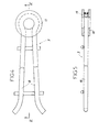
- the connecting rings 9 and 10 are advantageously made according to Figures 4 and 5, with a double metal rod 18 for anchoring in the concrete of a barrier element 2. On the curved middle part of the double rod 18, on either side thereof, are welded two washers metals 19 and 20. This embodiment leads to a set truly undeformable.
- the upper cover 13 is fitted on the area of junction of the two barrier elements 2, taking place in the respective hollowed out portions 8 of the ends of these elements 2.
- Screws side 21 are introduced through the holes 17 of the upper cover 13, and clamped in corresponding holes 22 formed in the parts recesses 8 of the two barrier elements 2, for fixing the upper cover 13 to these elements 2 and increase the rigidity of the assembly, while protecting the connecting members located below.
- the inclined flanks 4 of the barrier elements 2 advantageously receive retro-reflective tapes added, for example fixed by gluing, which achieve a efficient and durable horizontal signage, "highway" approved.
- the concrete safety barrier whose elements 2 are assembled as described above, in particular constitutes a barrier “Definitive”, which however remains removable and mobile.
- a barrier “Provisional” By simply joining the barrier elements 2 to the means of connecting rods 11 introduced through the rings 9 and 10, without using the lower 12 and upper 13 covers.
Abstract
Description
La présente invention concerne une barrière de sécurité en béton, pour des voies de circulation routières et autoroutières, la barrière étant composée d'éléments préfabriqués en béton à disposer sur le sol les uns à la suite des autres, et des moyens étant prévus pour assurer la liaison entre éléments de barrière consécutifs. Cette barrière de sécurité peut constituer une séparation provisoire de voies, dans un secteur où sont effectués des travaux tels que réfection ou élargissement de chaussée ; elle peut aussi constituer une séparation définitive, quoique mobile, entre deux voies de circulation.The present invention relates to a safety barrier made of concrete, for road and motorway traffic lanes, the barrier being made up of precast concrete elements to be placed on the ground one after the other, and means being provided to ensure the connection between consecutive barrier elements. This security barrier may constitute a temporary separation of tracks, in a sector where are carried out work such as repairing or widening the road; she can also constitute a definitive, albeit mobile, separation between two lanes.
Des barrières de sécurité de ce genre sont actuellement bien connues, et couramment utilisées. Elles se composent habituellement d'éléments en béton armé de longueur par exemple égale à environ 4 mètres, et de profil normalisé, élargi à sa base. Ces éléments de barrière sont pourvus, à leurs extrémités, d'anneaux métalliques horizontaux au travers desquels sont introduites des tiges métalliques verticales, qui assurent la liaison entre éléments consécutifs.Safety barriers of this kind are currently well known, and commonly used. They usually consist of reinforced concrete elements of length equal for example to about 4 meters, and of standardized profile, widened at its base. These barrier elements are provided, at their ends, with horizontal metal rings at the through which vertical metal rods are introduced, which provide the link between consecutive elements.
Comme on le conçoit aisément, les tiges verticales constituent ici des axes d'articulation, qui autorisent un certain désalignement entre éléments consécutifs pour permettre à la barrière de suivre une ligne courbe, mais qui nuisent à la rigidité de la liaison entre les éléments de barrière, alors que cette rigidité constitue un facteur essentiel pour l'efficacité de la barrière en cas de choc de véhicule.As is easily understood, the vertical rods constitute here articulation axes, which allow a certain misalignment between consecutive elements to allow the barrier to follow a line curve, but which affect the rigidity of the connection between the elements of barrier, whereas this rigidity constitutes an essential factor for the effectiveness of the barrier in the event of a vehicle impact.
Le brevet français n° 2 749 329, du même inventeur, décrit déjà une barrière de sécurité en béton perfectionnée, qui peut être utilisée soit comme séparation provisoire, soit comme séparation définitive, grâce à des poteaux introduits au travers des anneaux des éléments de barrière en béton, ces poteaux assurant la liaison de deux éléments de barrière consécutifs, et simultanément leur ancrage au sol. Toutefois, la rigidité de la liaison entre éléments de barrière consécutifs n'est ici améliorée que dans la mesure où les poteaux de liaison sont ancrés au sol, soit par enfoncement direct, soit par introduction dans des platines spéciales d'ancrage, elles-mêmes fixées au sol.French Patent No. 2,749,329, from the same inventor, describes already an improved concrete safety barrier, which can be used either as temporary separation or as final separation, thanks to posts inserted through the rings of the barrier elements in concrete, these posts ensuring the connection of two barrier elements consecutive, and simultaneously their anchoring to the ground. However, the rigidity of the connection between consecutive barrier elements is only improved here insofar as the connecting posts are anchored to the ground, either by direct insertion, either by introduction into special plates anchor, themselves fixed to the ground.
La présente invention vise à éliminer les inconvénients précédemment exposés, en fournissant une barrière de sécurité améliorée du point de vue de la rigidité de la liaison entre éléments, sans nécessité d'un ancrage au sol, et tout en augmentant la maniabilité et la sécurité de cette barrière.The present invention aims to eliminate the drawbacks previously exposed, providing an improved safety barrier from the point of view of the rigidity of the connection between elements, without necessity ground anchor, and while increasing the maneuverability and safety of this barrier.
A cet effet, l'invention a essentiellement pour objet une barrière de sécurité en béton, du genre ici considéré, avec moyens de liaison entre éléments de barrière consécutifs, comprenant des anneaux métalliques de liaison ancrés aux extrémités desdits éléments de barrière, et des tiges de liaison introduites verticalement au travers des anneaux, cette barrière de sécurité étant caractérisée en ce que, notamment pour la constitution d'une barrière définitive, mais mobile, les moyens de liaison entre éléments de barrière comprennent encore des capots métalliques inférieurs qui prennent place à la jonction de deux éléments de barrière consécutifs, dans des évidements formés sous la base élargie de ces éléments, chaque capot inférieur présentant un trou central d'axe vertical, tandis que les tiges de liaison sont conformées en vis, avec une tête apte à prendre appui sur l'un des anneaux de liaison, et une partie filetée prévue pour être introduite et vissée dans le trou central d'un capot inférieur.To this end, the invention essentially relates to a barrier of concrete safety, of the kind considered here, with means of connection between consecutive barrier elements, comprising metal rings of connection anchored at the ends of said barrier elements, and of the rods bond introduced vertically through the rings, this barrier of security being characterized in that, in particular for the constitution a definitive but mobile barrier, the means of connection between elements barriers still include lower metal covers which take place at the junction of two consecutive barrier elements, in recesses formed under the enlarged base of these elements, each cover lower with a central hole of vertical axis, while the rods of connection are screw-shaped, with a head capable of bearing on one connecting rings, and a threaded part intended to be introduced and screwed into the central hole of a lower cover.
Dans une forme de réalisation préférée de l'invention, les moyens de liaison entre éléments de barrière comprennent aussi des capots supérieurs de section en « U » renversé, prévus pour chevaucher les sommets de deux éléments de barrière consécutifs, à la jonction de ces éléments, des moyens étant prévus pour la fixation latérale démontable des capots supérieurs sur les éléments de barrière.In a preferred embodiment of the invention, the connecting means between barrier elements also include covers inverted U-shaped section superiors, designed to overlap the vertices of two consecutive barrier elements, at the junction of these elements, means being provided for the removable lateral fixing of the upper covers on the barrier elements.
Les évidements, formés sous la base élargie des éléments de barrière pour recevoir les capots inférieurs, sont avantageusement des évidements longitudinaux continus, s'étendant sur toute la longueur de ces éléments de barrière.The recesses, formed under the enlarged base of the elements of barrier to receive the lower covers, are advantageously continuous longitudinal recesses, extending over the entire length of these barrier elements.
Selon une autre caractéristique, les éléments de barrière présentent aussi des rainures longitudinales de sécurité pour manutention, ménagées de part et d'autre de leur partie supérieure étroite, ces rainures étant prolongées vers le haut, aux deux extrémités des éléments de barrière, par des parties évidées recevant les capots supérieurs.According to another characteristic, the barrier elements also have longitudinal safety grooves for handling, formed on either side of their narrow upper part, these grooves being extended upwards, at both ends of the elements of barrier, by hollowed out parts receiving the upper covers.
Dans l'ensemble, la barrière de sécurité objet de l'invention possède les avantages suivants :
- les moyens de liaison, comprenant les tiges de liaison serrées par vissage sur les capots inférieurs, avec obtention d'une tension verticale, assurent une liaison rigide dans la zone de raccordement de deux éléments de barrière consécutifs, ce qui permet de réaliser une barrière définitive mobile, sans ancrage de celle-ci dans le sol ;
- la rigidité de la liaison entre les éléments de barrière est encore renforcée, dans le cas où les moyens de liaison sont complétés par des capots supérieurs, qui enveloppent et « pincent » les sommets de ces éléments de barrière ;
- les capots supérieurs, mis en place, assurent aussi la protection des autres moyens de liaison (anneaux, tiges, capots inférieurs) qui sont situés en dessous ;
- prenant place dans des parties évidées des éléments en béton, les capots supérieurs sont encastrés et ne forment pas des parties en saillie ou anguleuses qui présenteraient un danger ;
- la présence d'un évidement longitudinal continu et de rainures longitudinales, sur les éléments de barrière en béton, permet d'alléger ces éléments, avec un gain de poids de l'ordre de 10 % ou plus, ce qui en facilite la manutention, et en réduit les coûts de fabrication et de transport, sans que la résistance de la barrière soit diminuée ;
- les rainures longitudinales évitent le risque de glissement, sur le béton, des pinces de manutention utilisées lors des opérations de pose, d'enlèvement ou de déplacement des éléments de barrière ;
- enfin, il reste possible de ne pas utiliser les capots inférieurs et supérieurs, et d'assembler les éléments de barrière par simple introduction verticale d'une tige de liaison dans les anneaux, pour la constitution d'une barrière provisoire délimitant par exemple une zone de chantier.
- the connecting means, comprising the connecting rods tightened by screwing on the lower covers, with obtaining a vertical tension, ensure a rigid connection in the connection area of two consecutive barrier elements, which makes it possible to produce a final barrier mobile, without anchoring it in the ground;
- the rigidity of the connection between the barrier elements is further reinforced, in the case where the connection means are completed by upper covers, which envelop and "pinch" the tops of these barrier elements;
- the upper covers, installed, also provide protection for the other connecting means (rings, rods, lower covers) which are located below;
- taking place in hollow parts of the concrete elements, the upper covers are recessed and do not form protruding or angular parts which would present a danger;
- the presence of a continuous longitudinal recess and longitudinal grooves, on the concrete barrier elements, makes it possible to lighten these elements, with a weight gain of the order of 10% or more, which facilitates handling, and reduces manufacturing and transport costs, without reducing the resistance of the barrier;
- the longitudinal grooves avoid the risk of sliding, on the concrete, of the handling clamps used during the operations of installation, removal or displacement of the barrier elements;
- finally, it remains possible not to use the lower and upper covers, and to assemble the barrier elements by simple vertical introduction of a connecting rod in the rings, for the constitution of a temporary barrier delimiting for example an area site.
De toute façon, l'invention sera mieux comprise à l'aide de la description qui suit, en référence qu dessin schématique annexé représentant, à titre d'exemple, une forme d'exécution de cette barrière de sécurité en béton pour voies routières et autoroutières :
- Figure 1 est une vue en perspective éclatée d'un tronçon de barrière de sécurité conforme à la présente invention, montrant ses divers composants ;
- Figure 2 est une vue de côté, avec coupes partielles, de la zone de liaison de deux éléments consécutifs de cette barrière de sécurité ;
- Figure 3 est une vue en bout d'un élément de barrière ;
- Figure 4 est une vue de face, à échelle agrandie, d'un anneau de liaison ;
- Figure 5 est une vue en coupe longitudinale de cet anneau, suivant V-V de figure 4.
- Figure 1 is an exploded perspective view of a safety barrier section according to the present invention, showing its various components;
- Figure 2 is a side view, with partial sections, of the connection zone of two consecutive elements of this safety barrier;
- Figure 3 is an end view of a barrier element;
- Figure 4 is a front view, on an enlarged scale, of a connecting ring;
- FIG. 5 is a view in longitudinal section of this ring, along VV of FIG. 4.
La barrière de sécurité, représentée au dessin, se compose
principalement d'éléments de barrière 2 préfabriqués, en béton armé, dont
l'un est visible en entier sur la figure 1. Chaque élément de barrière 2
possède une base élargie 3, des flancs inclinés 4 et une partie supérieure 5
relativement étroite, le profil de l'élément 2 étant bien visible sur la
figure 3.The safety barrier, shown in the drawing, consists of
mainly
Un évidement longitudinal continu 6 est ménagé, en position
médiane, sous la base élargie 3 de l'élément 2. Des rainures longitudinales
7 sont aussi ménagées de part et d'autre de la partie supérieure étroite 5
de l'élément 2, ces rainures 7 étant prolongées vers le haut, comme
indiqué en 8, aux deux extrémités de l'élément 2.A continuous
A chaque extrémité de l'élément de barrière 2 sont prévus deux
anneaux de liaison horizontaux 9 et 10, superposés, constitués par des
pièces métalliques ancrées dans le béton de l'élément 2.At each end of the
Les moyens de liaison entre éléments de barrière 2
comprennent encore, selon l'invention : des tiges de liaison 11, des capots
inférieurs 12 et des capots supérieurs 13.The means of connection between
Chaque tige de liaison 11, réalisée à la manière d'une vis,
possède une tête 14 par exemple à six pans dans sa partie supérieure, et
un filetage 15 dans sa partie inférieure.Each connecting
Chaque capot inférieur 12, réalisé en tôle ou par un tronçon de
profilé, possède une double paroi horizontale et deux ailes latérales. Un trou
taraudé 16 d'axe vertical, complémentaire du filetage 15 de la tige de
liaison 11, est ménagé dans la paroi horizontale supérieure du capot 12, au
centre de celle-ci.Each
Chaque capot supérieur 13, réalisé lui aussi en tôle ou par un
tronçon de profilé, possède une section en forme générale de « U »
renversé. Des trous 17 sont percés dans les deux ailes du capot supérieur
13, vers les deux extrémités de ce capot 13.Each
Les anneaux de liaison 9 et 10 sont avantageusement réalisés
selon les figures 4 et 5, avec une double tige métallique 18 d'ancrage dans
le béton d'un élément de barrière 2. Sur la partie médiane cintrée de la
double tige 18, de part et d'autre de celle-ci, sont soudées deux rondelles
métalliques 19 et 20. Ce mode de réalisation conduit à un ensemble
véritablement indéformable.The connecting
Pour l'assemblage de deux éléments de barrière 2 consécutifs,
les extrémités de ces éléments 2 sont rapprochées de manière à aligner
leurs anneaux de liaison 9 et 10 respectifs suivant un même axe vertical.
De plus, un capot inférieur 12 est placé à la jonction des deux éléments de
barrière 2, au niveau du sol dans les évidements longitudinaux 6 respectifs
de ces éléments 2. Une tige de liaison 11 est engagée par le haut dans les
quatre anneaux 9 et 10 alignés, et cette tige de liaison 11 est vissée, par
son filetage 15, dans le trou taraudé 16 du capot inférieur 12. Le serrage
de la tige de liaison 11 est poursuivi jusqu'à obtenir une mise en tension
suffisante de cette tige 11, dont la tête 14 prend alors appui fermement
sur l'anneau 9 supérieur, provoquant une mise en compression des deux
éléments de barrière 2 par l'intermédiaire du capot inférieur 12 - voir en
particulier la figure 2. La conformation de l'anneau 9, selon les figures 4 et
5, permet à la tête 14 de la tige 11 de prendre appui à plat fortement sur
l'une des rondelles 19 ou 20, sans risque de déformation de cet anneau 9
par pliage.For the assembly of two
En complément, le capot supérieur 13 est emboíté sur la zone
de jonction des deux éléments de barrière 2, en prenant place dans les
parties évidées 8 respectives des extrémités de ces éléments 2. Des vis
latérales 21 sont introduites au travers des trous 17 du capot supérieur 13,
et serrées dans des trous 22 correspondants ménagés dans les parties
évidées 8 des deux éléments de barrière 2, pour fixer le capot supérieur 13
à ces éléments 2 et augmenter la rigidité de l'assemblage, tout en
protégeant les organes de liaison situés au-dessous.In addition, the
Comme indiqué en 23 sur la figure 1, les flancs inclinés 4 des
éléments de barrière 2 reçoivent avantageusement des bandes rétro-réfléchissantes
rapportées, par exemple fixées par collage, qui réalisent une
signalisation horizontale efficace et durable, homologuée « autoroute ». As indicated at 23 in FIG. 1, the
La barrière de sécurité en béton, dont les éléments 2 sont
assemblés comme décrit précédemment, constitue notamment une barrière
« définitive », laquelle reste toutefois démontable et mobile. A l'aide des
mêmes éléments 2, il est aussi possible de réaliser une barrière
« provisoire », en réunissant simplement les éléments de barrière 2 au
moyen de tiges de liaison 11 introduites au travers des anneaux 9 et 10,
sans utiliser les capots inférieurs 12 et supérieurs 13.The concrete safety barrier, whose
Pour la manutention des éléments de barrière 2, lors de la pose
d'une barrière, de son enlèvement ou de son déplacement, on utilise des
pinces mécaniques ou hydrauliques qui agrippent lesdits éléments 2 par
leurs rainures longitudinales 7, ce qui évite tout glissement dangereux,
notamment par temps de pluie ou en cas de gel.For
L'on ne s'éloignerait pas du cadre de l'invention, telle que définie dans les revendications annexées, par une modification de la forme des éléments en béton, notamment en ce qui concerne leur profil qui est susceptible d'évolution, par exemple vers une forme trapézoïdale ou autre, ou par une modification des détails de forme des capots inférieurs et/ou supérieurs, ou des anneaux, ou par une adaptation du dispositif à des éléments de barrière particuliers, tels que des éléments terminaux à extrémités abaissées.One would not depart from the scope of the invention, such as defined in the appended claims, by a modification of the form concrete elements, in particular with regard to their profile which is susceptible of evolution, for example towards a trapezoidal shape or other, or by modifying the shape details of the lower covers and / or or rings, or by adapting the device to particular barrier elements, such as terminal elements to lowered ends.
Claims (7)
Applications Claiming Priority (2)
| Application Number | Priority Date | Filing Date | Title |
|---|---|---|---|
| FR0007376A FR2810055B1 (en) | 2000-06-08 | 2000-06-08 | CONCRETE SAFETY BARRIER FOR HIGHWAYS AND HIGHWAYS |
| FR0007376 | 2000-06-08 |
Publications (1)
| Publication Number | Publication Date |
|---|---|
| EP1162315A1 true EP1162315A1 (en) | 2001-12-12 |
Family
ID=8851117
Family Applications (1)
| Application Number | Title | Priority Date | Filing Date |
|---|---|---|---|
| EP01420120A Withdrawn EP1162315A1 (en) | 2000-06-08 | 2001-05-21 | Concrete safety-barrier for roads |
Country Status (2)
| Country | Link |
|---|---|
| EP (1) | EP1162315A1 (en) |
| FR (1) | FR2810055B1 (en) |
Cited By (19)
| Publication number | Priority date | Publication date | Assignee | Title |
|---|---|---|---|---|
| WO2002101153A1 (en) * | 2001-06-13 | 2002-12-19 | Poundfield Products Limited | Wall block for a freestanding, especially retaining wall and method for erecting such a wall |
| EP1284325A2 (en) * | 2001-08-14 | 2003-02-19 | Maba Fertigteilindustrie GmbH | Concrete wall element |
| EP1455021A1 (en) | 2003-03-07 | 2004-09-08 | Balisage-Securité-Service- B.S.S. | Metal separator element for traffic lanes |
| FR2862674A1 (en) * | 2003-11-20 | 2005-05-27 | Bonna Sabla | Safety barrier fabricating method for road traffic lane, involves connecting two beam units by mutual articulation around two axes perpendicular to ground, where each axis is placed with respect to frontal surfaces |
| FR2862672A1 (en) * | 2003-11-20 | 2005-05-27 | Bonna Sabla | Safety barrier fabricating method for road traffic lane, involves connecting two beam units by mutual articulation around two axes perpendicular to ground, where each axis is placed with respect to frontal surfaces |
| FR2866038A1 (en) | 2004-02-05 | 2005-08-12 | Entpr Deschiron | DEVICE FOR ASSEMBLING TWO PREFABRICATED CONCRETE SECURITY BARRIER MODULES, ROAD SAFETY BARRIER OR MOTOR VEHICLE INCLUDING APPLICATION AND MODULE FOR SUCH A BARRIER |
| WO2005113240A1 (en) | 2004-05-19 | 2005-12-01 | Xsys Print Solutions Deutschland Gmbh | Method for producing flexographic printing plates using direct laser engraving |
| GB2417257A (en) * | 2004-08-21 | 2006-02-22 | Milbury Systems Ltd | Pre-cast concrete wall unit |
| AT502935B1 (en) * | 2005-11-04 | 2008-03-15 | Maba Fertigteilind Gmbh | guide wall |
| US7419765B2 (en) | 2003-11-27 | 2008-09-02 | Xsys Print Solutions Deutschland Gmbh | Method for producing flexographic printing plates by means of laser engraving |
| WO2010125008A1 (en) * | 2009-04-27 | 2010-11-04 | Arnaldo Sorci | Protective fixing bracket |
| WO2013033766A1 (en) * | 2011-09-05 | 2013-03-14 | Javelin Pacific Pty Ltd | Vehicle separation barrier |
| EP2712962B1 (en) * | 2012-10-01 | 2018-04-11 | Horst Luther | Mobile protection wall |
| EP3587670A1 (en) * | 2018-06-29 | 2020-01-01 | GP Spolka z Ograniczona Odpowiedzialnoscia | Mobile safety barrier and method for assembling mobile safety barrier |
| WO2020070556A1 (en) * | 2018-10-05 | 2020-04-09 | Vandorf Mb1 Inc. | Mobile traffic barrier |
| FR3092346A1 (en) * | 2019-02-05 | 2020-08-07 | Balisage Securite Service | CONNECTION DEVICE FOR CONCRETE WALL ELEMENTS, CONCRETE BARRIER AND RELATED PROCESS |
| EP3842593A1 (en) * | 2019-12-27 | 2021-06-30 | GP Spolka z Ograniczona Odpowiedzialnoscia | Mobile safety barrier and method for assembling mobile safety barrier |
| GB2605835A (en) * | 2021-04-16 | 2022-10-19 | Poundfield Precast Ltd | Modular wall unit |
| US11933004B2 (en) * | 2018-01-10 | 2024-03-19 | Saferoads Pty Ltd. | Barrier |
Families Citing this family (1)
| Publication number | Priority date | Publication date | Assignee | Title |
|---|---|---|---|---|
| CN115948984A (en) * | 2021-06-15 | 2023-04-11 | 山西高速集团朔神有限责任公司 | Prefabricated anti-collision wall for assembled bridge and construction method of prefabricated anti-collision wall |
Citations (4)
| Publication number | Priority date | Publication date | Assignee | Title |
|---|---|---|---|---|
| DE4320720A1 (en) * | 1993-06-17 | 1994-12-22 | Philipp Stephanie | Crash barriers consisting of waste materials (recycled materials) |
| DE29606934U1 (en) * | 1995-04-21 | 1996-08-14 | Spacek Zdenek | Interchangeable lane boundaries |
| FR2749329A1 (en) * | 1996-06-04 | 1997-12-05 | Plattard Sa | Temporary or permanent safety barrier for roads and motorways |
| US5836714A (en) * | 1994-07-20 | 1998-11-17 | Off The Wall Production, Inc. | Control barrier systems |
-
2000
- 2000-06-08 FR FR0007376A patent/FR2810055B1/en not_active Expired - Lifetime
-
2001
- 2001-05-21 EP EP01420120A patent/EP1162315A1/en not_active Withdrawn
Patent Citations (4)
| Publication number | Priority date | Publication date | Assignee | Title |
|---|---|---|---|---|
| DE4320720A1 (en) * | 1993-06-17 | 1994-12-22 | Philipp Stephanie | Crash barriers consisting of waste materials (recycled materials) |
| US5836714A (en) * | 1994-07-20 | 1998-11-17 | Off The Wall Production, Inc. | Control barrier systems |
| DE29606934U1 (en) * | 1995-04-21 | 1996-08-14 | Spacek Zdenek | Interchangeable lane boundaries |
| FR2749329A1 (en) * | 1996-06-04 | 1997-12-05 | Plattard Sa | Temporary or permanent safety barrier for roads and motorways |
Cited By (27)
| Publication number | Priority date | Publication date | Assignee | Title |
|---|---|---|---|---|
| WO2002101153A1 (en) * | 2001-06-13 | 2002-12-19 | Poundfield Products Limited | Wall block for a freestanding, especially retaining wall and method for erecting such a wall |
| GB2377949B (en) * | 2001-06-13 | 2005-07-20 | Poundfield Products Ltd | Apparatus and method for constructing a freestanding wall |
| EP1284325A2 (en) * | 2001-08-14 | 2003-02-19 | Maba Fertigteilindustrie GmbH | Concrete wall element |
| EP1284325A3 (en) * | 2001-08-14 | 2004-01-02 | Maba Fertigteilindustrie GmbH | Concrete wall element |
| EP1455021A1 (en) | 2003-03-07 | 2004-09-08 | Balisage-Securité-Service- B.S.S. | Metal separator element for traffic lanes |
| FR2852035A1 (en) | 2003-03-07 | 2004-09-10 | Balisage Securite Service B S | MATALLIC SEPARATOR FOR ROADWAYS |
| FR2862674A1 (en) * | 2003-11-20 | 2005-05-27 | Bonna Sabla | Safety barrier fabricating method for road traffic lane, involves connecting two beam units by mutual articulation around two axes perpendicular to ground, where each axis is placed with respect to frontal surfaces |
| FR2862672A1 (en) * | 2003-11-20 | 2005-05-27 | Bonna Sabla | Safety barrier fabricating method for road traffic lane, involves connecting two beam units by mutual articulation around two axes perpendicular to ground, where each axis is placed with respect to frontal surfaces |
| US7419765B2 (en) | 2003-11-27 | 2008-09-02 | Xsys Print Solutions Deutschland Gmbh | Method for producing flexographic printing plates by means of laser engraving |
| FR2866038A1 (en) | 2004-02-05 | 2005-08-12 | Entpr Deschiron | DEVICE FOR ASSEMBLING TWO PREFABRICATED CONCRETE SECURITY BARRIER MODULES, ROAD SAFETY BARRIER OR MOTOR VEHICLE INCLUDING APPLICATION AND MODULE FOR SUCH A BARRIER |
| WO2005113240A1 (en) | 2004-05-19 | 2005-12-01 | Xsys Print Solutions Deutschland Gmbh | Method for producing flexographic printing plates using direct laser engraving |
| US7749399B2 (en) | 2004-05-19 | 2010-07-06 | Xsys Print Solutions Deutschland Gmbh | Method for producing flexographic printing plates using direct laser engraving |
| GB2417257A (en) * | 2004-08-21 | 2006-02-22 | Milbury Systems Ltd | Pre-cast concrete wall unit |
| GB2417257B (en) * | 2004-08-21 | 2009-08-12 | Milbury Systems Ltd | Precast concrete wall units |
| AT502935B1 (en) * | 2005-11-04 | 2008-03-15 | Maba Fertigteilind Gmbh | guide wall |
| WO2010125008A1 (en) * | 2009-04-27 | 2010-11-04 | Arnaldo Sorci | Protective fixing bracket |
| WO2013033766A1 (en) * | 2011-09-05 | 2013-03-14 | Javelin Pacific Pty Ltd | Vehicle separation barrier |
| EP2712962B1 (en) * | 2012-10-01 | 2018-04-11 | Horst Luther | Mobile protection wall |
| US11933004B2 (en) * | 2018-01-10 | 2024-03-19 | Saferoads Pty Ltd. | Barrier |
| EP3587670A1 (en) * | 2018-06-29 | 2020-01-01 | GP Spolka z Ograniczona Odpowiedzialnoscia | Mobile safety barrier and method for assembling mobile safety barrier |
| WO2020070556A1 (en) * | 2018-10-05 | 2020-04-09 | Vandorf Mb1 Inc. | Mobile traffic barrier |
| US11028545B2 (en) | 2018-10-05 | 2021-06-08 | Vandorf MB 1 Inc. | Mobile traffic barrier |
| FR3092346A1 (en) * | 2019-02-05 | 2020-08-07 | Balisage Securite Service | CONNECTION DEVICE FOR CONCRETE WALL ELEMENTS, CONCRETE BARRIER AND RELATED PROCESS |
| EP3693511A1 (en) * | 2019-02-05 | 2020-08-12 | Balisage Securite Service | Connection device for low concrete wall elements, associated concrete barrier and method |
| EP3842593A1 (en) * | 2019-12-27 | 2021-06-30 | GP Spolka z Ograniczona Odpowiedzialnoscia | Mobile safety barrier and method for assembling mobile safety barrier |
| GB2605835A (en) * | 2021-04-16 | 2022-10-19 | Poundfield Precast Ltd | Modular wall unit |
| WO2022219343A1 (en) * | 2021-04-16 | 2022-10-20 | Poundfield Precast Limited | Modular wall unit |
Also Published As
| Publication number | Publication date |
|---|---|
| FR2810055A1 (en) | 2001-12-14 |
| FR2810055B1 (en) | 2004-05-21 |
Similar Documents
| Publication | Publication Date | Title |
|---|---|---|
| EP1162315A1 (en) | Concrete safety-barrier for roads | |
| FR2586724A1 (en) | METALLIC BARRIER, PARTICULARLY FOR THE EQUIPMENT OF ROADWAYS | |
| FR2529627A1 (en) | DEVICE FOR FIXING MOUNTING PARTS TO A CONCRETE WALL | |
| FR2749329A1 (en) | Temporary or permanent safety barrier for roads and motorways | |
| EP1561864A1 (en) | Assembly device for two modules of precast concrete road barriers | |
| FR2846673A1 (en) | Safety barrier for roadside has additional larger slide profile attached to existing mountings by bolting | |
| FR2660676A1 (en) | SLIDE WITH DOUBLE SLIDING ELEMENT FOR RETAINING VEHICLES ON A ROAD. | |
| FR2554491A1 (en) | MODULAR FENCE FORMED OF SECTIONS WITH AT LEAST ONE HORIZONTAL SMOOTH BETWEEN VERTICAL CYLINDRICAL POSTS | |
| WO1991007081A1 (en) | Multifunction support for greenhouse framework | |
| FR2678007A1 (en) | Device for fastening, on a post, a rail intended to equip a civil engineering construction for a road traffic lane | |
| EP3339511A1 (en) | Security barrier including a succession of elements, each forming a crosspiece, which can be mutually deployed, closed and engaged with rotating post | |
| FR2811344A1 (en) | Motor road safety barrier has round-section timber rails reinforced by steel strips in slots fastened to supports by bolts and spacers | |
| FR2463247A1 (en) | Temporary site fencing on hard standing - has base frame with fixing pins to engage sockets in uprights | |
| CH683540A5 (en) | Portable road-works or crowd control barrier - consists of elongated sections which fit together at ends and have widely separated rails on either side | |
| CH676864A5 (en) | Movable road barrier - comprises sections with concrete bases and safety rails fixed to posts | |
| EP1308584B1 (en) | Fence with a multitude of posts and wired panels and method of erecting the same | |
| FR2660098A1 (en) | TRAFFIC SIGN. | |
| FR2502682A1 (en) | Door or gate for fence - has two uprights which are integral with prefabricated sill | |
| FR2517767A1 (en) | ADJUSTABLE FLANGE WITH SELF-LOCKING EFFECT | |
| FR2861113A1 (en) | Pole and cross piece connection part for constructing fence, has male part with pivot line perpendicular to two sides and curved side which is defined by radius equal to distance separating inner sides of tubular end of crosspiece | |
| EP1526229B1 (en) | Connecting piece between a post and a rail and fence equipped with such a connecting piece | |
| FR2567933A1 (en) | Removable protective barrier | |
| CH690826A5 (en) | Removable fastening for motor road crash barrier comprises triple peg attached to bracket engaging with lugs on barrier rail | |
| FR2621340A1 (en) | Metal frame | |
| BE694905A (en) |
Legal Events
| Date | Code | Title | Description |
|---|---|---|---|
| PUAI | Public reference made under article 153(3) epc to a published international application that has entered the european phase |
Free format text: ORIGINAL CODE: 0009012 |
|
| AK | Designated contracting states |
Kind code of ref document: A1 Designated state(s): AT BE CH CY DE DK ES FI FR GB GR IE IT LI LU MC NL PT SE TR |
|
| AX | Request for extension of the european patent |
Free format text: AL;LT;LV;MK;RO;SI |
|
| AKX | Designation fees paid | ||
| REG | Reference to a national code |
Ref country code: DE Ref legal event code: 8566 |
|
| STAA | Information on the status of an ep patent application or granted ep patent |
Free format text: STATUS: THE APPLICATION IS DEEMED TO BE WITHDRAWN |
|
| 18D | Application deemed to be withdrawn |
Effective date: 20020613 |