EP1561708A1 - Plate-forme modulaire démontable pour déchetterie - Google Patents
Plate-forme modulaire démontable pour déchetterie Download PDFInfo
- Publication number
- EP1561708A1 EP1561708A1 EP20050352003 EP05352003A EP1561708A1 EP 1561708 A1 EP1561708 A1 EP 1561708A1 EP 20050352003 EP20050352003 EP 20050352003 EP 05352003 A EP05352003 A EP 05352003A EP 1561708 A1 EP1561708 A1 EP 1561708A1
- Authority
- EP
- European Patent Office
- Prior art keywords
- elements
- plates
- slab
- vertical uprights
- consecutive
- Prior art date
- Legal status (The legal status is an assumption and is not a legal conclusion. Google has not performed a legal analysis and makes no representation as to the accuracy of the status listed.)
- Granted
Links
- 239000002699 waste material Substances 0.000 claims description 14
- 230000000295 complement effect Effects 0.000 claims description 4
- 230000000284 resting effect Effects 0.000 claims description 4
- 239000004576 sand Substances 0.000 claims description 3
- 238000009434 installation Methods 0.000 description 5
- 239000000463 material Substances 0.000 description 4
- 229910052782 aluminium Inorganic materials 0.000 description 2
- XAGFODPZIPBFFR-UHFFFAOYSA-N aluminium Chemical compound [Al] XAGFODPZIPBFFR-UHFFFAOYSA-N 0.000 description 2
- 206010001488 Aggression Diseases 0.000 description 1
- 240000000966 Allium tricoccum Species 0.000 description 1
- 229910000831 Steel Inorganic materials 0.000 description 1
- 230000016571 aggressive behavior Effects 0.000 description 1
- 230000015556 catabolic process Effects 0.000 description 1
- 238000004140 cleaning Methods 0.000 description 1
- 239000000470 constituent Substances 0.000 description 1
- 238000006731 degradation reaction Methods 0.000 description 1
- 238000007599 discharging Methods 0.000 description 1
- 230000007774 longterm Effects 0.000 description 1
- 229910052751 metal Inorganic materials 0.000 description 1
- 239000002184 metal Substances 0.000 description 1
- 238000000926 separation method Methods 0.000 description 1
- 230000035939 shock Effects 0.000 description 1
- 239000010959 steel Substances 0.000 description 1
- 239000000126 substance Substances 0.000 description 1
Images


Classifications
-
- B—PERFORMING OPERATIONS; TRANSPORTING
- B65—CONVEYING; PACKING; STORING; HANDLING THIN OR FILAMENTARY MATERIAL
- B65F—GATHERING OR REMOVAL OF DOMESTIC OR LIKE REFUSE
- B65F1/00—Refuse receptacles; Accessories therefor
- B65F1/0033—Refuse receptacles; Accessories therefor specially adapted for segregated refuse collecting, e.g. receptacles with several compartments; Combination of receptacles
-
- Y—GENERAL TAGGING OF NEW TECHNOLOGICAL DEVELOPMENTS; GENERAL TAGGING OF CROSS-SECTIONAL TECHNOLOGIES SPANNING OVER SEVERAL SECTIONS OF THE IPC; TECHNICAL SUBJECTS COVERED BY FORMER USPC CROSS-REFERENCE ART COLLECTIONS [XRACs] AND DIGESTS
- Y02—TECHNOLOGIES OR APPLICATIONS FOR MITIGATION OR ADAPTATION AGAINST CLIMATE CHANGE
- Y02W—CLIMATE CHANGE MITIGATION TECHNOLOGIES RELATED TO WASTEWATER TREATMENT OR WASTE MANAGEMENT
- Y02W30/00—Technologies for solid waste management
- Y02W30/10—Waste collection, transportation, transfer or storage, e.g. segregated refuse collecting, electric or hybrid propulsion
Definitions
- the present invention relates to the field of installations intended for the collection of waste, and more particularly to unloading facilities for vehicles carrying garbage.
- It relates to a modular device consisting of a distribution slab serving as support to an elevated platform and ramps, slab, platform and ramps being assembled from elementary units positioned and held together by specific means.
- a Modular equipment consisting of a platform equipped with ramps inclined, consisting of aluminum elements assembling in varying numbers according to the desired configuration.
- the patent application FR 93 07801 describes a facility also realized in using modular elements. Tippers arranged against each other, are endowed at their upper edge of a load bearing floor that constitutes a single deck able to support the vehicle whose contents are to be unloaded.
- the slab formed of juxtaposed plates, has the function of providing a flat surface, horizontal and stable, on which the supporting elements and the elements access. It has a footprint at least as important as the platform it supports. It can be expanded to support also waste collection bins. The flatness and stability of the slab are necessary for the cohesion of the device in its together.
- the juxtaposed supporting elements are supported on the slab and form a continuous plane raised horizontal suitable for receiving vehicles. It is easy to understand that for a given device, the vertical uprights of the supporting elements have a higher stop horizontal and all have the same height. In general, we will choose a height comparable to the height of the buckets placed at the periphery of the device, a model usually employed for waste collection.
- the vertical amounts of the elements have an inclined top stop and have varying heights to ensure gradual and continuous elevation from the ground level to the level of the platform.
- each type of modular elements constituting the structure of the device is produced in a limited number of formats, preferably in a single format, said format constituting the unit of the module.
- height being fixed as indicated above, all the plates or all the elements occupy a given area.
- the ratio of the surfaces will be an integer.
- the existence of many elements of symmetry favors a greater modularity.
- the uprights are placed on the longest side of the supporting elements or access elements.
- Sectional transverse said elements have an inverted U shape, the branches of the U giving the width of the considered element.
- a platform is composed of several rows of consecutive and contiguous elements. These definitions extend to format elements square. The strength calculations of the materials apply without difficulty to establish the optimal dimensions and limits of the constituent elements of the device according to the invention.
- the device is characterized by its stability and strength, not only characteristics of the modular elements that make it up, but also because of the connecting means providing cohesion between the plates, the bearing elements and the elements access.
- These connecting means comprise, in particular, wedging means for elements in relation to each other, that is to say means ensuring their correct relative positioning and immobilization in a given position during the mounting of the device or during use, and this because of their own conformation, without use additional parts.
- the means of connection also include means for fixing the elements together, using additional parts.
- the latter comprises means of vertical wedging of the plates forming the distribution slab.
- the plates must form a flat surface, so that the supporting elements and the access elements are continuous horizontal support. A tilting or moving in the vertical direction of a plate with respect to the other should be avoided.
- the faces lateral sections in contact with two contiguous plates have a horizontal notch forming a light of polygonal section in which is housed a tube of the same section.
- the latter comprises means lateral wedging of the supporting elements and access elements on the slab.
- the first The function of such a wedging is to prevent an element from slipping sideways. Indeed, side posts must be positioned on the plates and must not be able to release from this support.
- the means for lateral wedging of an element carrying or of an access element consist of two grooves made in the slab to the plumb two vertical uprights of said element, each of said grooves receiving the end one of said vertical uprights.
- the grooves have an asymmetrical profile, their depth being less on the outer side of said element
- the end of the uprights adopts the shape complementary to said profile.
- Such a profile is of particular interest when it is desired to give cohesion between a set of contiguous bearing elements and the corresponding support plates as will be explained later.
- fixation can be implemented. This fixation can be based on the chaining principle.
- said fixing means may comprise at least a system consisting of two rigid legs fixed together at their ends by two threaded rods each passing a vertical amount of said two consecutive elements. So, said rigid tabs are placed on either side of the vertical uprights and straddling two consecutive vertical uprights. Everything is held tight by bolts screwed onto the threading said rods.
- said fixing means comprise at least one system consisting of two rigid tabs secured together at their ends by two threaded rods each passing through two vertical uprights joined by two pairs of consecutive elements. Everything is maintained tightened by bolts screwed on the thread of said rods.
- the device according to the invention is advantageously composed of plates and elements of the same width.
- the plates are twice as short as the bearing elements.
- the junctions between elements may also be shifted with respect to the junctions between plates, or well they can coincide.
- a mixed assembly is carried out, in which the junctions between contiguous bearing members coincide with the junctions between plates, and the junctions between consecutive bearing elements are offset from the junctions between plates.
- the two vertical uprights of an element are supported on both opposite edges of one or more plates.
- the device according to the invention comprises means to prevent separation of the plates forming the distribution slab. This characteristic is even more important when the plates and elements have the same width, and that given array of plates supports a given array of elements. Indeed, if the plates slide sideways, the elements resting on them will move apart, revealing faults at the platform level.
- the grooves have a profile asymmetrical, and that their depth is less on the external side of said element, the end vertical uprights adopting the shape complementary to said profile.
- a profile cooperating with the fastening system as described, is of particular interest because it gives maximum cohesion between a set of bearing elements contiguous and the corresponding support plates.
- the distribution slab is placed on a bed of sand.
- a railing can be installed on the periphery of the platform.
- the supporting and access elements comprise means for fixing a railing, which may consist, for example, of holes in which can be fixed balustrades.
- the plates, the bearing elements and the access elements are prefabricated with concrete.
- the device according to the invention is specially designed for unloading objects or materials from the platform into skips placed below.
- the collection of wastes brought by vehicles is the main application. However everything else a job requiring a vehicle to overhang a receptacle Anything is also possible.
- Figure 1 shows a three-dimensional view of an unloading platform 1 accessible by two access ramps 2 and equipped with a guardrail 6.
- the platform 1 is accessible by two inclined access ramps. Waste receptacles are placed on the ground and adjoin the platform 1 in various places.
- the platform is composed of 20 bearing elements 3 forming the horizontal plane 48.
- Each ramp 2 is composed of two access elements 4.
- a railing 6 is installed on the periphery of the platform, it stops at the level of the buckets 5 to allow the approach of vehicles and the unloading of waste.
- Figures 2-a and 2-b show in top view, two different configurations of unloading device.
- the locations provided for the collection bins 5 are materialized by concrete slabs 7.
- FIG. 3 is shown in longitudinal section, a ramp 2 composed of several access members 4, extending through the first bearing member 3 of the platform 1.
- the access elements 4 and bearing elements 3 are supported on the distribution slab 8 composed of several plates 9 juxtaposed on a bed of sand 10.
- Fixing systems 17 are placed at the junction of the various elements 3, 4.
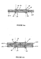
- FIG 4-a appear in horizontal section, four supporting elements 3, arranged in two pairs contiguous of consecutive elements.
- the bearing elements 3 are each constituted two vertical uprights 12 and a horizontal upper cross member 13.
- the elements 3-a and 3-b are contiguous by the surface of a vertical upright, respectively 12-a and 12-b, likewise that the elements 3-c and 3-d are contiguous by the surface of a vertical upright, respectively 12-c and 12-d.
- the elements 3-a and 3-c are consecutive, as are the elements 3-b and 3-d.
- the junction of the four supporting elements 3 is ensured by the fastening system 17.
- These supporting elements are totally or partially supported by a set of ten plates 4.
- the longitudinal junction 40 between bearing elements 3 contiguous coincides with the junction 40 'of the plates 4.
- the transverse junction 50 between bearing elements 3 consecutive is offset with respect to the junctions 50 'between the plates 4.
- FIGS. 5-a, 5-b on the one hand, and 6-a, 6-b on the other hand.
- FIG. 5-a illustrates in section along the axis A-A ', the detail of a junction between elements 3 and support plates 9.
- Figure 5-b is a section of the same junction according to the axis B-B '.
- the side faces of the two adjoining plates 9-a and 9-b are in contact. They have a horizontal notch 20 forming a square section light 21 in which is housed a metal tube of the same section.
- two grooves 22-a and 22-b are formed at the edge of the plates 9-a and 9-b, and receive the end of the uprights 12-a and 12-b respectively said grooves have an asymmetric profile, their depth being less on the outer side of said element.
- the end of vertical uprights 12-a and 12-b adopt the complementary shape of said profile.
- FIG. 6-b Such a system 17 is shown in FIG. 6-b. It is composed of two rigid legs 23 and 24 fixed together at their ends 25 and 26 by two rods 27 and 28.
- the rod 28 passes through the two vertical uprights 12-a and 12-b contiguous two adjoining elements 3-a and 3-b.
- the rod 27 passes through the two vertical uprights contiguous 12-c and 12-d of the two adjoining elements 3-c and 3-d.
- Bolts 30 hold tight said rods and said legs of the system 17.
- FIG. 6-a shows a fastening system 17 of two consecutive bearing elements 3, this configuration meeting at the periphery of the device.
- Two rigid legs 23 and 24 are fixed together at their ends 25 and 26 by two threaded rods 27 and 28.
- the rod 28 crosses the vertical upright 12-e.
- the rod 27 passes through the vertical upright 12-f.
- Bolts 30 hold said rods and said legs of the system 17 tight.
Landscapes
- Engineering & Computer Science (AREA)
- Mechanical Engineering (AREA)
- Forms Removed On Construction Sites Or Auxiliary Members Thereof (AREA)
- Mutual Connection Of Rods And Tubes (AREA)
- Refuse Collection And Transfer (AREA)
- Connection Of Plates (AREA)
- Bridges Or Land Bridges (AREA)
- Refuse Receptacles (AREA)
Abstract
Description
- une pluralité de plaques juxtaposées formant une dalle de répartition,
- une pluralité d'éléments portants juxtaposés formant un plan horizontal surélevé, lesdits éléments portants étant constitués de deux montants verticaux prenant appui sur la dalle de répartition et d'une traverse supérieure horizontale,
- une pluralité d'éléments d'accès formant au moins un plan incliné continu depuis la dalle de répartition jusqu'au plan horizontal surélevé, lesdits éléments d'accès étant constitués de deux montants verticaux prenant appui sur la dalle de répartition et d'une traverse supérieure inclinée, et
- des moyens de liaison entre les plaques, les éléments portants et les éléments d'accès.
- forme modulable en fonction de la capacité souhaitée et de la géométrie du terrain,
- installation sur toutes les surfaces sans chape,
- nettoyage facile,
- solidité à toute épreuve,
- démontable et remontable sans dégradation,
- transportable,
- peu onéreux.
- des moyens de calage latéral d'un élément, constitués de deux rainures pratiquées dans la dalle à l'aplomb des deux montants verticaux dudit élément, lesdites rainures recevant l'extrémité desdits montants verticaux, et
- au moins un système composé de deux pattes rigides fixées entre elles à leurs extrémités par deux tiges filetées traversant chacune un montant vertical de deux éléments consécutifs.
- des moyens de calage latéral d'un élément, constitués de deux rainures pratiquées dans la dalle à l'aplomb des montants verticaux dudit élément, lesdites rainures recevant l'extrémité desdits montants verticaux, et
- au moins un système de fixation composé de deux pattes rigides fixées entre elles à leurs extrémités par deux tiges filetées traversant chacune deux montants verticaux accolés de deux paires d'éléments consécutifs.
- des moyens de calage vertical 14 des plaques 9 formant la dalle de répartition 8;
- des moyens de calage latéral 15 des éléments portants 3 sur la dalle 8, et
- des moyens de fixation 16 entre les éléments portants 3.
Claims (19)
- Dispositif destiné au déchargement de déchets constitué d'une plate-forme surélevée (1) et de rampes d'accès inclinées (2), caractérisé en ce qu' il comprend :une pluralité de plaques juxtaposées (9) formant une dalle de répartition (8),une pluralité d'éléments portants (3) juxtaposés formant un plan horizontal surélevé (48), lesdits éléments portants étant constitués de deux montants verticaux (12) prenant appui sur la dalle de répartition (8) et d'une traverse supérieure (13) horizontale,une pluralité d'éléments d'accès (4) formant au moins un plan incliné continu depuis la dalle de répartition (8) jusqu'au plan horizontal surélevé (48), lesdits éléments d'accès étant constitués de deux montants verticaux (12) prenant appui sur la dalle de répartition (8) et d'une traverse supérieure (13) inclinée, etdes moyens de liaison (11) entre les plaques (9), les éléments portants (3) et les éléments d'accès (4).
- Dispositif selon la revendication 1, caractérisé en ce qu' il comprend des moyens de calage vertical (14) des plaques (9) formant la dalle de répartition (8).
- Dispositif selon la revendication 2, caractérisé en ce que les faces latérales en contact de deux plaques (9) contiguës comportent une encoche horizontale (20) formant une lumière (21) de section polygonale dans laquelle est logé un tube de même section.
- Dispositif selon l'une des revendications 1 à 3, caractérisé en ce qu' il comprend des moyens de calage latéral (15) des éléments portants (3) et des éléments d'accès (4) sur la dalle (8).
- Dispositif selon la revendication 4, caractérisé en ce que les moyens de calage latéral d'un élément portant (3) ou d'un élément d'accès (4) sont constitués de deux rainures (22-a, 22-b) pratiquées dans la dalle (8) à l'aplomb des montants verticaux (12) dudit élément, lesdites rainures recevant l'extrémité desdits montants verticaux.
- Dispositif selon la revendication 5, caractérisé en ce que les rainures (22-a, 22-b) ont un profil dissymétrique, leur profondeur étant moindre du côté externe dudit élément, et l'extrémité des montants verticaux adopte la forme complémentaire dudit profil.
- Dispositif selon l'une des revendications précédentes, caractérisé en ce qu' il comprend des moyens de fixation (16) de deux éléments (3, 4) consécutifs entre eux.
- Dispositif selon la revendication 7, caractérisé en ce que les moyens de fixation (16) comprennent au moins un système (17) composé de deux pattes rigides (23, 24) fixées entre elles à leurs extrémités (25, 26) par deux tiges filetées (27, 28) traversant chacune un montant vertical (12) de deux éléments (3, 4) consécutifs.
- Dispositif selon l'une des revendications précédentes, caractérisé en ce qu' il comprend des moyens de fixation (16) de quatre éléments (3, 4) entre eux, lesdits éléments étant disposés en une première paire d'éléments consécutifs accolée à une seconde paire d'éléments consécutifs.
- Dispositif selon la revendication 9, caractérisé en ce que les moyens de fixation (16) comprennent au moins un système (17) composé de deux pattes rigides (23, 24) fixées entre elles à leurs extrémités (25, 26) par deux tiges filetées (27, 28) traversant chacune deux montants verticaux (12) accolés de deux paires d'éléments (3, 4) consécutifs.
- Dispositif selon l'une des revendications précédentes, caractérisé en ce que les plaques (9) et les éléments (3, 4) sont de même largeur.
- Dispositif selon l'une des revendications précédentes, caractérisé en ce que les deux montants verticaux (12) d'un élément (3, 4) prennent appui sur les deux bords opposés d'une ou de plusieurs plaques (9).
- Dispositif selon l'une des revendications précédentes, caractérisé en ce qu' il comprend des moyens pour empêcher l'écartement des plaques (9) formant la dalle de répartition (8).
- Dispositif selon la revendication 13, caractérisé en ce que lesdits moyens pour empêcher l'écartement des plaques (9) comprennent des moyens de calage latéral (15) des éléments (3, 4) sur les plaques (9), associés à des moyens de fixation (16) desdits éléments entre eux.
- Dispositif selon la revendication 14, caractérisé en ce qu' il comprend :des moyens de calage latéral (15) d'un élément (3, 4), constitués de deux rainures (22-a, 22-b) pratiquées dans la dalle (8) à l'aplomb des montants verticaux (12) desdits éléments, lesdites rainures recevant l'extrémité desdits montants verticaux, etau moins un système de fixation (17) composé de deux pattes rigides (23, 24) fixées entre elles à leurs extrémités (25, 26) par deux tiges filetées (27, 28) traversant chacune un montant vertical (12) desdits éléments.
- Dispositif selon la revendication 14, caractérisé en ce qu 'il comprend :des moyens de calage latéral (15) d'un élément (3, 4), constitués de deux rainures (22-a, 22-b) pratiquées dans la dalle (8) à l'aplomb des montants verticaux (12) dudit élément, lesdites rainures recevant l'extrémité desdits montants verticaux, etau moins un système de fixation (17) composé de deux pattes rigides (23, 24) fixées entre elles à leurs extrémités (25, 26) par deux tiges filetées (27, 28) traversant chacune deux montants verticaux (12) accolés de deux paires d'éléments consécutifs.
- Dispositif selon l'une des revendications précédentes, caractérisé en ce que la dalle de répartition (8) est posée sur un lit de sable (10).
- Dispositif selon l'une des revendications précédentes, caractérisé en ce que les éléments (3, 4) comportent des moyens de fixation d'un garde-corps (6).
- Dispositif selon l'une quelconque des revendications précédentes, caractérisé en ce que les plaques (9), les éléments portants (3) et les éléments d'accès (4) sont préfabriqués en béton.
Applications Claiming Priority (2)
| Application Number | Priority Date | Filing Date | Title |
|---|---|---|---|
| FR0401037A FR2865666B1 (fr) | 2004-02-04 | 2004-02-04 | Plateforme modulaire demontable pour dechetterie |
| FR0401037 | 2004-02-04 |
Publications (2)
| Publication Number | Publication Date |
|---|---|
| EP1561708A1 true EP1561708A1 (fr) | 2005-08-10 |
| EP1561708B1 EP1561708B1 (fr) | 2006-11-29 |
Family
ID=34673889
Family Applications (1)
| Application Number | Title | Priority Date | Filing Date |
|---|---|---|---|
| EP20050352003 Active EP1561708B1 (fr) | 2004-02-04 | 2005-01-31 | Plate-forme modulaire démontable pour déchetterie |
Country Status (6)
| Country | Link |
|---|---|
| EP (1) | EP1561708B1 (fr) |
| AT (1) | ATE346807T1 (fr) |
| DE (1) | DE602005000284T2 (fr) |
| ES (1) | ES2277324T3 (fr) |
| FR (1) | FR2865666B1 (fr) |
| PT (1) | PT1561708E (fr) |
Cited By (6)
| Publication number | Priority date | Publication date | Assignee | Title |
|---|---|---|---|---|
| FR2899212A1 (fr) * | 2006-03-30 | 2007-10-05 | Philippe Lamine | Dechetterie modulaire en beton |
| WO2011051573A1 (fr) * | 2009-10-30 | 2011-05-05 | Modulo Beton | Plate-forme modulaire demontable pour dechetterie |
| FR2981966A1 (fr) * | 2011-10-28 | 2013-05-03 | Tech Des Metaux | Dispositif de securisation d'une benne de dechetterie |
| FR3064987A1 (fr) * | 2017-04-05 | 2018-10-12 | La Catalane De Recuperation | Dispositif de securisation pour une benne de collecte, et dispositif de collecte correspondant |
| CN109051849A (zh) * | 2018-08-23 | 2018-12-21 | 吉林市城通科技有限公司 | 一种积木式登车桥及其使用方法 |
| FR3091859A1 (fr) * | 2019-01-21 | 2020-07-24 | G. Gillard Sas | Dispositif modulaire pour realiser une collecte selective de dechets |
Families Citing this family (3)
| Publication number | Priority date | Publication date | Assignee | Title |
|---|---|---|---|---|
| ES2369598B1 (es) * | 2009-04-07 | 2012-10-15 | Binomi Punt Arquitectura Slp | Habitáculo con dispositivos para la recogida y clasificación selectiva de distintos tipos de residuos de aparatos eléctricos y electrónicos dotándolos de un almacenamiento seguro y su proceso de funcionamiento. |
| IT1400279B1 (it) * | 2010-05-14 | 2013-05-24 | Truzzi Prefabbricati S R L Ora Truzzi S P A | Piattaforma modulare perfezionata per la realizzazione di discariche sopraelevate |
| FR3131911B1 (fr) | 2022-01-14 | 2024-04-05 | Marc Descours | Module d’assemblage pour une installation de déchèterie à impact écologique positif élargi, installation et procédé sur la base d’un tel module |
Citations (4)
| Publication number | Priority date | Publication date | Assignee | Title |
|---|---|---|---|---|
| GB2195676A (en) * | 1986-10-10 | 1988-04-13 | Newell Dunford Limited | Modular staging |
| FR2687939A1 (fr) * | 1992-02-28 | 1993-09-03 | Est Sarl Financiere Mecanique | Installation de recolte et de tri de dechets. |
| FR2689916A1 (fr) * | 1992-04-10 | 1993-10-15 | Jobard Daniel | Installation de récupération d'objets notamment de déchets solides ou liquides. |
| FR2706791A1 (en) * | 1993-06-22 | 1994-12-30 | Gesta Sarl | Self-supported waste unit |
-
2004
- 2004-02-04 FR FR0401037A patent/FR2865666B1/fr not_active Expired - Fee Related
-
2005
- 2005-01-31 AT AT05352003T patent/ATE346807T1/de not_active IP Right Cessation
- 2005-01-31 DE DE200560000284 patent/DE602005000284T2/de active Active
- 2005-01-31 PT PT05352003T patent/PT1561708E/pt unknown
- 2005-01-31 ES ES05352003T patent/ES2277324T3/es active Active
- 2005-01-31 EP EP20050352003 patent/EP1561708B1/fr active Active
Patent Citations (4)
| Publication number | Priority date | Publication date | Assignee | Title |
|---|---|---|---|---|
| GB2195676A (en) * | 1986-10-10 | 1988-04-13 | Newell Dunford Limited | Modular staging |
| FR2687939A1 (fr) * | 1992-02-28 | 1993-09-03 | Est Sarl Financiere Mecanique | Installation de recolte et de tri de dechets. |
| FR2689916A1 (fr) * | 1992-04-10 | 1993-10-15 | Jobard Daniel | Installation de récupération d'objets notamment de déchets solides ou liquides. |
| FR2706791A1 (en) * | 1993-06-22 | 1994-12-30 | Gesta Sarl | Self-supported waste unit |
Cited By (11)
| Publication number | Priority date | Publication date | Assignee | Title |
|---|---|---|---|---|
| FR2899212A1 (fr) * | 2006-03-30 | 2007-10-05 | Philippe Lamine | Dechetterie modulaire en beton |
| WO2011051573A1 (fr) * | 2009-10-30 | 2011-05-05 | Modulo Beton | Plate-forme modulaire demontable pour dechetterie |
| EP2493783A1 (fr) | 2009-10-30 | 2012-09-05 | Modulo Beton | Plate-forme modulaire demontable pour dechetterie |
| JP2013509342A (ja) * | 2009-10-30 | 2013-03-14 | モデュロ ベトン | ゴミ処理施設用の分解可能なモジュール式プラットフォーム |
| US8869331B2 (en) | 2009-10-30 | 2014-10-28 | Modulo Beton | Dismountable modular platform for waste disposal facility |
| EA025138B1 (ru) * | 2009-10-30 | 2016-11-30 | Модюло Бетон | Разборная модульная платформа для разгрузки отходов |
| CN102596762B (zh) * | 2009-10-30 | 2017-07-11 | 混凝土模公司 | 用于废物处理设施的模块式可拆卸平台 |
| FR2981966A1 (fr) * | 2011-10-28 | 2013-05-03 | Tech Des Metaux | Dispositif de securisation d'une benne de dechetterie |
| FR3064987A1 (fr) * | 2017-04-05 | 2018-10-12 | La Catalane De Recuperation | Dispositif de securisation pour une benne de collecte, et dispositif de collecte correspondant |
| CN109051849A (zh) * | 2018-08-23 | 2018-12-21 | 吉林市城通科技有限公司 | 一种积木式登车桥及其使用方法 |
| FR3091859A1 (fr) * | 2019-01-21 | 2020-07-24 | G. Gillard Sas | Dispositif modulaire pour realiser une collecte selective de dechets |
Also Published As
| Publication number | Publication date |
|---|---|
| ES2277324T3 (es) | 2007-07-01 |
| ATE346807T1 (de) | 2006-12-15 |
| PT1561708E (pt) | 2007-02-28 |
| FR2865666A1 (fr) | 2005-08-05 |
| EP1561708B1 (fr) | 2006-11-29 |
| DE602005000284T2 (de) | 2007-06-28 |
| FR2865666B1 (fr) | 2006-04-28 |
| DE602005000284D1 (de) | 2007-01-11 |
Similar Documents
| Publication | Publication Date | Title |
|---|---|---|
| EP1561708B1 (fr) | Plate-forme modulaire démontable pour déchetterie | |
| FR2962953A1 (fr) | Extension laterale rabattable attenante a au moins un plan de chargement d'un vehicule porte-charges | |
| EP2493783B1 (fr) | Plate-forme modulaire demontable pour dechetterie | |
| EP0844335A1 (fr) | Barrière mobile et ensemble formé par assemblage d'une pluralité de telles barrières | |
| EP1380696A1 (fr) | Dispositif de retenue modulaire et procédé de pose d'un tel dispositif | |
| EP2392734A1 (fr) | Module de séparation de voies en béton et barrière de séparation comprenant plusieurs modules de ce type | |
| FR2975416A1 (fr) | Support de lestage par dallette | |
| WO2015190901A1 (fr) | Dispositif mobile pour produire de l'energie photovoltaïque | |
| FR2687939A1 (fr) | Installation de recolte et de tri de dechets. | |
| EP2381034B1 (fr) | Dispositif destiné à équiper un joint de dilatation entre des dalles de béton | |
| FR2602253A1 (fr) | Dispositif perfectionne de liaison de panneaux metalliques pour aire d'aerodrome | |
| FR2516114A1 (fr) | Elements d'ossature de support pour plaques ou grilles de couverture | |
| BE1013038A6 (fr) | Remorque de transport pour une structure interchangeable deposee, en particulier une plate-forme interchangeable. | |
| EP1493686A1 (fr) | Soubassement faisant office de berceau pour le positionnement d'un conteneur d'une benne ou similaire | |
| FR2727445A1 (fr) | Point d'arret d'autobus | |
| EP3767057A1 (fr) | Equipement pour former un parking aerien comprenant des modules de tablier en bois | |
| FR3129963A1 (fr) | Mobilier urbain présentant une mise en place simplifiée | |
| CH719197A2 (fr) | Mobilier urbain transportable, à mise en place simplifiée. | |
| EP4190992A1 (fr) | Mobilier urbain présentant une mise en place simplifiée | |
| EP3564452A1 (fr) | Structure tridimensionnelle a monter pour combler un bassin enterre de retention des eaux de pluie | |
| FR3112156A3 (fr) | Dispositif, ensemble de parties comprenant ce dispositif et procédé de raccordement d’éléments longitudinaux | |
| EP3788212A1 (fr) | Procede de fabrication d'un plancher, plancher et element de coffrage a etai integre associes | |
| FR3043991A1 (fr) | Structure d'accueil pour conteneur pour place de parking | |
| FR3086678A1 (fr) | Module hybride metal-beton separateur de voies de circulation et procede de realisation d'une barriere de separation | |
| FR2811348A1 (fr) | Construction modulaire |
Legal Events
| Date | Code | Title | Description |
|---|---|---|---|
| PUAI | Public reference made under article 153(3) epc to a published international application that has entered the european phase |
Free format text: ORIGINAL CODE: 0009012 |
|
| AK | Designated contracting states |
Kind code of ref document: A1 Designated state(s): AT BE BG CH CY CZ DE DK EE ES FI FR GB GR HU IE IS IT LI LT LU MC NL PL PT RO SE SI SK TR |
|
| AX | Request for extension of the european patent |
Extension state: AL BA HR LV MK YU |
|
| 17P | Request for examination filed |
Effective date: 20060105 |
|
| AKX | Designation fees paid |
Designated state(s): AT BE BG CH CY CZ DE DK EE ES FI FR GB GR HU IE IS IT LI LT LU MC NL PL PT RO SE SI SK TR |
|
| GRAP | Despatch of communication of intention to grant a patent |
Free format text: ORIGINAL CODE: EPIDOSNIGR1 |
|
| GRAS | Grant fee paid |
Free format text: ORIGINAL CODE: EPIDOSNIGR3 |
|
| GRAA | (expected) grant |
Free format text: ORIGINAL CODE: 0009210 |
|
| AK | Designated contracting states |
Kind code of ref document: B1 Designated state(s): AT BE BG CH CY CZ DE DK EE ES FI FR GB GR HU IE IS IT LI LT LU MC NL PL PT RO SE SI SK TR |
|
| PG25 | Lapsed in a contracting state [announced via postgrant information from national office to epo] |
Ref country code: IE Free format text: LAPSE BECAUSE OF FAILURE TO SUBMIT A TRANSLATION OF THE DESCRIPTION OR TO PAY THE FEE WITHIN THE PRESCRIBED TIME-LIMIT Effective date: 20061129 Ref country code: FI Free format text: LAPSE BECAUSE OF FAILURE TO SUBMIT A TRANSLATION OF THE DESCRIPTION OR TO PAY THE FEE WITHIN THE PRESCRIBED TIME-LIMIT Effective date: 20061129 Ref country code: PL Free format text: LAPSE BECAUSE OF FAILURE TO SUBMIT A TRANSLATION OF THE DESCRIPTION OR TO PAY THE FEE WITHIN THE PRESCRIBED TIME-LIMIT Effective date: 20061129 Ref country code: AT Free format text: LAPSE BECAUSE OF FAILURE TO SUBMIT A TRANSLATION OF THE DESCRIPTION OR TO PAY THE FEE WITHIN THE PRESCRIBED TIME-LIMIT Effective date: 20061129 Ref country code: LT Free format text: LAPSE BECAUSE OF FAILURE TO SUBMIT A TRANSLATION OF THE DESCRIPTION OR TO PAY THE FEE WITHIN THE PRESCRIBED TIME-LIMIT Effective date: 20061129 Ref country code: RO Free format text: LAPSE BECAUSE OF FAILURE TO SUBMIT A TRANSLATION OF THE DESCRIPTION OR TO PAY THE FEE WITHIN THE PRESCRIBED TIME-LIMIT Effective date: 20061129 Ref country code: CZ Free format text: LAPSE BECAUSE OF FAILURE TO SUBMIT A TRANSLATION OF THE DESCRIPTION OR TO PAY THE FEE WITHIN THE PRESCRIBED TIME-LIMIT Effective date: 20061129 Ref country code: SK Free format text: LAPSE BECAUSE OF FAILURE TO SUBMIT A TRANSLATION OF THE DESCRIPTION OR TO PAY THE FEE WITHIN THE PRESCRIBED TIME-LIMIT Effective date: 20061129 Ref country code: NL Free format text: LAPSE BECAUSE OF FAILURE TO SUBMIT A TRANSLATION OF THE DESCRIPTION OR TO PAY THE FEE WITHIN THE PRESCRIBED TIME-LIMIT Effective date: 20061129 Ref country code: SI Free format text: LAPSE BECAUSE OF FAILURE TO SUBMIT A TRANSLATION OF THE DESCRIPTION OR TO PAY THE FEE WITHIN THE PRESCRIBED TIME-LIMIT Effective date: 20061129 |
|
| REG | Reference to a national code |
Ref country code: GB Ref legal event code: FG4D Free format text: NOT ENGLISH |
|
| REG | Reference to a national code |
Ref country code: CH Ref legal event code: EP |
|
| REG | Reference to a national code |
Ref country code: IE Ref legal event code: FG4D Free format text: LANGUAGE OF EP DOCUMENT: FRENCH |
|
| REF | Corresponds to: |
Ref document number: 602005000284 Country of ref document: DE Date of ref document: 20070111 Kind code of ref document: P |
|
| PG25 | Lapsed in a contracting state [announced via postgrant information from national office to epo] |
Ref country code: MC Free format text: LAPSE BECAUSE OF NON-PAYMENT OF DUE FEES Effective date: 20070131 |
|
| PG25 | Lapsed in a contracting state [announced via postgrant information from national office to epo] |
Ref country code: BG Free format text: LAPSE BECAUSE OF FAILURE TO SUBMIT A TRANSLATION OF THE DESCRIPTION OR TO PAY THE FEE WITHIN THE PRESCRIBED TIME-LIMIT Effective date: 20070228 Ref country code: DK Free format text: LAPSE BECAUSE OF FAILURE TO SUBMIT A TRANSLATION OF THE DESCRIPTION OR TO PAY THE FEE WITHIN THE PRESCRIBED TIME-LIMIT Effective date: 20070228 Ref country code: SE Free format text: LAPSE BECAUSE OF FAILURE TO SUBMIT A TRANSLATION OF THE DESCRIPTION OR TO PAY THE FEE WITHIN THE PRESCRIBED TIME-LIMIT Effective date: 20070228 |
|
| REG | Reference to a national code |
Ref country code: PT Ref legal event code: SC4A Free format text: AVAILABILITY OF NATIONAL TRANSLATION Effective date: 20070213 |
|
| GBT | Gb: translation of ep patent filed (gb section 77(6)(a)/1977) |
Effective date: 20070214 |
|
| PG25 | Lapsed in a contracting state [announced via postgrant information from national office to epo] |
Ref country code: IS Free format text: LAPSE BECAUSE OF FAILURE TO SUBMIT A TRANSLATION OF THE DESCRIPTION OR TO PAY THE FEE WITHIN THE PRESCRIBED TIME-LIMIT Effective date: 20070329 |
|
| NLV1 | Nl: lapsed or annulled due to failure to fulfill the requirements of art. 29p and 29m of the patents act | ||
| REG | Reference to a national code |
Ref country code: IE Ref legal event code: FD4D |
|
| REG | Reference to a national code |
Ref country code: ES Ref legal event code: FG2A Ref document number: 2277324 Country of ref document: ES Kind code of ref document: T3 |
|
| PLBE | No opposition filed within time limit |
Free format text: ORIGINAL CODE: 0009261 |
|
| STAA | Information on the status of an ep patent application or granted ep patent |
Free format text: STATUS: NO OPPOSITION FILED WITHIN TIME LIMIT |
|
| 26N | No opposition filed |
Effective date: 20070830 |
|
| PG25 | Lapsed in a contracting state [announced via postgrant information from national office to epo] |
Ref country code: GR Free format text: LAPSE BECAUSE OF FAILURE TO SUBMIT A TRANSLATION OF THE DESCRIPTION OR TO PAY THE FEE WITHIN THE PRESCRIBED TIME-LIMIT Effective date: 20070301 |
|
| REG | Reference to a national code |
Ref country code: FR Ref legal event code: CL |
|
| PG25 | Lapsed in a contracting state [announced via postgrant information from national office to epo] |
Ref country code: EE Free format text: LAPSE BECAUSE OF FAILURE TO SUBMIT A TRANSLATION OF THE DESCRIPTION OR TO PAY THE FEE WITHIN THE PRESCRIBED TIME-LIMIT Effective date: 20061129 |
|
| PG25 | Lapsed in a contracting state [announced via postgrant information from national office to epo] |
Ref country code: CY Free format text: LAPSE BECAUSE OF FAILURE TO SUBMIT A TRANSLATION OF THE DESCRIPTION OR TO PAY THE FEE WITHIN THE PRESCRIBED TIME-LIMIT Effective date: 20061129 |
|
| PG25 | Lapsed in a contracting state [announced via postgrant information from national office to epo] |
Ref country code: HU Free format text: LAPSE BECAUSE OF FAILURE TO SUBMIT A TRANSLATION OF THE DESCRIPTION OR TO PAY THE FEE WITHIN THE PRESCRIBED TIME-LIMIT Effective date: 20070530 Ref country code: TR Free format text: LAPSE BECAUSE OF FAILURE TO SUBMIT A TRANSLATION OF THE DESCRIPTION OR TO PAY THE FEE WITHIN THE PRESCRIBED TIME-LIMIT Effective date: 20061129 |
|
| REG | Reference to a national code |
Ref country code: FR Ref legal event code: CL Name of requester: TRAVAUX TRANSPORT MANUTENTION, FR Effective date: 20130705 Ref country code: FR Ref legal event code: CL Name of requester: TCMC BVBA, BE Effective date: 20130705 |
|
| REG | Reference to a national code |
Ref country code: ES Ref legal event code: RD2A Effective date: 20140130 |
|
| REG | Reference to a national code |
Ref country code: ES Ref legal event code: RD2A Effective date: 20140617 |
|
| REG | Reference to a national code |
Ref country code: FR Ref legal event code: PLFP Year of fee payment: 12 |
|
| REG | Reference to a national code |
Ref country code: GB Ref legal event code: 732E Free format text: REGISTERED BETWEEN 20160512 AND 20160518 |
|
| REG | Reference to a national code |
Ref country code: FR Ref legal event code: PLFP Year of fee payment: 13 |
|
| REG | Reference to a national code |
Ref country code: ES Ref legal event code: RD2A Effective date: 20170627 |
|
| REG | Reference to a national code |
Ref country code: FR Ref legal event code: PLFP Year of fee payment: 14 |
|
| REG | Reference to a national code |
Ref country code: ES Ref legal event code: RD2A Effective date: 20180219 |
|
| REG | Reference to a national code |
Ref country code: DE Ref legal event code: R082 Ref document number: 602005000284 Country of ref document: DE Representative=s name: WUNDERLICH & HEIM PATENTANWAELTE PARTNERSCHAFT, DE |
|
| PGFP | Annual fee paid to national office [announced via postgrant information from national office to epo] |
Ref country code: IT Payment date: 20230110 Year of fee payment: 19 Ref country code: BE Payment date: 20230117 Year of fee payment: 19 |
|
| PGFP | Annual fee paid to national office [announced via postgrant information from national office to epo] |
Ref country code: PT Payment date: 20231218 Year of fee payment: 20 Ref country code: LU Payment date: 20231227 Year of fee payment: 20 Ref country code: FR Payment date: 20231116 Year of fee payment: 20 |
|
| PGFP | Annual fee paid to national office [announced via postgrant information from national office to epo] |
Ref country code: ES Payment date: 20240207 Year of fee payment: 20 |
|
| PGFP | Annual fee paid to national office [announced via postgrant information from national office to epo] |
Ref country code: DE Payment date: 20240213 Year of fee payment: 20 Ref country code: GB Payment date: 20240119 Year of fee payment: 20 Ref country code: CH Payment date: 20240201 Year of fee payment: 20 |