EP1454083B1 - Schaltvorrichtung zum schalten von wenigstens zwei schaltbaren gängen eines schaltgetriebes - Google Patents
Schaltvorrichtung zum schalten von wenigstens zwei schaltbaren gängen eines schaltgetriebes Download PDFInfo
- Publication number
- EP1454083B1 EP1454083B1 EP02804572A EP02804572A EP1454083B1 EP 1454083 B1 EP1454083 B1 EP 1454083B1 EP 02804572 A EP02804572 A EP 02804572A EP 02804572 A EP02804572 A EP 02804572A EP 1454083 B1 EP1454083 B1 EP 1454083B1
- Authority
- EP
- European Patent Office
- Prior art keywords
- switching
- selector
- selecting
- pivot axis
- shift
- Prior art date
- Legal status (The legal status is an assumption and is not a legal conclusion. Google has not performed a legal analysis and makes no representation as to the accuracy of the status listed.)
- Expired - Lifetime
Links
Images



Classifications
-
- F—MECHANICAL ENGINEERING; LIGHTING; HEATING; WEAPONS; BLASTING
- F16—ENGINEERING ELEMENTS AND UNITS; GENERAL MEASURES FOR PRODUCING AND MAINTAINING EFFECTIVE FUNCTIONING OF MACHINES OR INSTALLATIONS; THERMAL INSULATION IN GENERAL
- F16H—GEARING
- F16H63/00—Control outputs from the control unit to change-speed- or reversing-gearings for conveying rotary motion or to other devices than the final output mechanism
- F16H63/02—Final output mechanisms therefor; Actuating means for the final output mechanisms
- F16H63/30—Constructional features of the final output mechanisms
- F16H63/34—Locking or disabling mechanisms
- F16H63/3408—Locking or disabling mechanisms the locking mechanism being moved by the final actuating mechanism
-
- F—MECHANICAL ENGINEERING; LIGHTING; HEATING; WEAPONS; BLASTING
- F16—ENGINEERING ELEMENTS AND UNITS; GENERAL MEASURES FOR PRODUCING AND MAINTAINING EFFECTIVE FUNCTIONING OF MACHINES OR INSTALLATIONS; THERMAL INSULATION IN GENERAL
- F16H—GEARING
- F16H63/00—Control outputs from the control unit to change-speed- or reversing-gearings for conveying rotary motion or to other devices than the final output mechanism
- F16H63/02—Final output mechanisms therefor; Actuating means for the final output mechanisms
- F16H63/08—Multiple final output mechanisms being moved by a single common final actuating mechanism
- F16H63/20—Multiple final output mechanisms being moved by a single common final actuating mechanism with preselection and subsequent movement of each final output mechanism by movement of the final actuating mechanism in two different ways, e.g. guided by a shift gate
-
- F—MECHANICAL ENGINEERING; LIGHTING; HEATING; WEAPONS; BLASTING
- F16—ENGINEERING ELEMENTS AND UNITS; GENERAL MEASURES FOR PRODUCING AND MAINTAINING EFFECTIVE FUNCTIONING OF MACHINES OR INSTALLATIONS; THERMAL INSULATION IN GENERAL
- F16H—GEARING
- F16H63/00—Control outputs from the control unit to change-speed- or reversing-gearings for conveying rotary motion or to other devices than the final output mechanism
- F16H63/02—Final output mechanisms therefor; Actuating means for the final output mechanisms
- F16H63/08—Multiple final output mechanisms being moved by a single common final actuating mechanism
- F16H63/20—Multiple final output mechanisms being moved by a single common final actuating mechanism with preselection and subsequent movement of each final output mechanism by movement of the final actuating mechanism in two different ways, e.g. guided by a shift gate
- F16H63/206—Multiple final output mechanisms being moved by a single common final actuating mechanism with preselection and subsequent movement of each final output mechanism by movement of the final actuating mechanism in two different ways, e.g. guided by a shift gate the final output mechanisms being mounted coaxially on a single shaft, e.g. mono rail shift mechanism
Definitions
- the invention relates to a switching device for switching at least two via movable switching elements switchable gears of a gearbox with at least one pivotable about a pivot axis and along the Swivel axis sliding shift finger and the switching device continues with at least one synchronous with the shift finger about the pivot axis pivotable and slidable along the pivot axis locking member, the optionally switching at least one of the gears on a switching element locks, wherein the locking member to be locked switching element to a in the locking switching device facing portion of the switching element at least then attacks when the blocking element to be blocked endeavors to lock itself in the locked Switching direction to move, according to the preamble of Claim 1 and as known from DE 10011272 C.
- Such a switching device is described in DE 31 25 632.
- the switching device is for switching five forward gears and one reverse gear used in a manual transmission.
- Shift shaft is stuck and thus synchronized with the shift shaft swiveling and sliding a shift finger.
- On switching elements in shape of sliding shift rails sit in a known manner shift forks. With The shift forks can be switched individually.
- the shift rails have recesses in the base of a fork-like Wegles into which the shift finger can engage to select an alley.
- Lock cam On the shift finger to DE 31 25 632 C1 are two locking members in the form of Lock cam radially from the shift finger or the shift shaft. These Locking members extend on both sides in the direction of displacement along the Swivel axis of the shift shaft from the shift finger on the shift shaft along.
- the locking cams fix on the one hand each of the switching elements in the neutral position and lock the other hand, inexact preselection of the switching device against the shifting of gears as well as let only the switching from one gear at a time.
- the slot of the slot guide extends radially into the locking cam in the direction of shift shaft and is in the direction of the shift shaft slightly wider than that Width of Wegmaules considered in the direction of the shift shaft.
- One Switching a corridor in the selected alley is only after exact area code the lane possible, d. h., When the slot guide and the wall of the Muzzle exactly aligned with each other in the pivoting plane of the shift finger are.
- the pivoting shift finger shifts the shift rod, by pressing against the relevant wall of the recess in the switching mouth running. Depending on the pivoting direction of the shift finger then dives one of the Wegmaul limiting wall sections in the slot guide and the Gang can be engaged.
- the switching and blocking device described in DE 31 25 632 C1 is for applications suitable in which individual switching elements to shift forks, such as Heidelbergffleuler, with their openings exactly in the direction of the shift shaft are arranged and aligned along its pivot axis one behind the other.
- Such a designed device can only be used in applications, in which the Siemens insomniauler in the direction of the shift shaft in a row arranged and aligned with each other in the neutral position.
- Another is the production of such a locking cam provided with shift finger usually with time-consuming and costly machining connected. This concerns in particular the incorporation of the slot guide.
- the shift finger and the locking cam are relatively solid Parts that adversely affect the overall weight of the vehicle transmission. Often also claimed by such a device Space relatively large.
- the object of the invention is therefore to provide a switching device with versatile usable and material-saving and inexpensive to produce locking members to accomplish.
- the selection and switching movements for selecting the streets and switching the individual lanes assigned gears are in manual transmissions by means of a or multiple actuators transferred to the switching elements.
- the Design of the actuators depends on the design of the Transmission. There are, for example, shift shafts, shift drums or more pivotable relative to the transmission or rotatable and mostly along the pivot axis used sliding elements. Under actuators So all are the elements to be understood with one or the other several shift fingers, switching cams or functionally identical switching elements are provided and with these switching elements on switching elements, such as shift forks, Shift rails with one or more shift forks, shift rails or similar, to select and / or shift gears.
- the switching of one of the gears of the gearbox is in the considered Switching device initiated with the choice of the alley.
- the alley are one or alternatively two gears switchable.
- Choosing the alley is in the Switching device according to the invention preferably with a displacement of the actuating element initiated along its pivot axis. This is a Shift finger brought by moving into a starting position, from the then by an optional pivoting of the actuating element in the one or other pivoting direction associated with one or the other of the selected alley Gear is switchable.
- the shift finger is in the selected alley in a positive connection with one or two switching elements, the then usually longitudinally movable on a clutch with a synchronizer act.
- the positive connection is z. B.
- the shift mouth is depending on Design of the switching device formed on a switching arm, which either directly connected to a shift fork or the one connected to a Shift fork provided shift rail attacks.
- the switching mouth can also directly be formed on the shift fork or the shift rail.
- the shift fork For example, actuates a shift sleeve of the clutch.
- the switching device can also be used in applications in which the actuating element to select the lane, first panned and then to Shift the gear is moved along its pivot axis.
- the switching device in manual transmissions is conceivable in which the Switching element for switching a gear must be swiveled.
- the task of the bracket and / or other locking members is the switching elements and thus to fix the gears in unswitched neutral position and the switching device or the gears at unexact switching control and against unintentional engagement of a corridor to lock.
- manual transmissions are in usually four to five gears at a time to lock the switching of one to allow further passage. Therefore, preferably more of the Used locking members according to the invention in a manual transmission.
- everyone the hanger locks one or two gears.
- One or more at the same time acting locking members leave optionally at most switching one of Gears in the manual transmission too.
- the or the bracket are independent arranged by the position of the or the shift finger on the shift shaft or the like.
- the movements the locking member or the locking members in the locked position movements the shift shaft are used causally to select one of the intended choosing alley. Since the locking member or the locking members synchronously with the Shift finger slidably and pivotally on an actuator of the Switching device are attached locks the selection movement to select the alley thus also at the same time the courses to be blocked. Is an intended dialing completed, stands or stand the locking members in the locked position and the gears to be locked are in the subsequent to the dialing process Switching operation by pivoting the selector shaft against Faulty switching disabled.
- the bracket With the displacement of the actuating element, for example a shift shaft, the bracket is in a blocking position to the switching element to be locked brought.
- the bracket is moved by means of the switching shaft in a position, in which he at least one limiting the surface of the switching element as well as in the direction to be blocked switching direction pointing section or at least one pointing in the direction of switching point of the section on a blocking element opposite or already acts on this.
- At least the bracket will then touch that section or point if the switching element to be locked unintentionally in the locked switching direction should be moved. An unwanted movement of the switching element in Switching direction is prevented because the bow movement of the switching element in this direction stands in the way.
- the bracket or at least a part of the bracket so the switching element in the switching direction, or is this to be such that a panning or moving a switching element in the to be locked (s) switching direction (s) for insertion the locked corridor is not possible.
- the switching element to be locked moves with the blocking element inevitably against movement in the switching direction Strap or already attacks in the direction of the unwanted switching movement to the locking member.
- Unwanted movements of the switching element arise z. B. by an interaction of gravity with forces due to vibrations on one in the switching device to be switched vertically switching element or by in Fahr plante occurring forces due to accelerations at one in the Switching device horizontally oriented switching element. Under unwanted Movements are also faulty when not exactly a switching element to understand aligned switching element.
- the pointing in the switching direction section is on the switching element z. B. on formed a switching jaw limiting inner edges.
- locking cams or the like functionally identical blocking element which emanates from the switching element and rests in the blocking position on the bracket.
- the shift shaft must therefore the blocking element of the switching elements to be blocked so that the respective or the respective bracket by means of movements of the shift shaft, at least in the movement space located in the switching direction to be blocked of the portion or portions dips on the respective blocking element or immerse yourself.
- the shift shaft or similar actuators to switch one of the gears still panned.
- the switching element is Therefore, at the blocking element at least designed so that the bracket or at least the attacking part of the strap during the switching process enough space for unhindered panning in the one or other pivoting direction is available.
- the shift shaft is thus not hindered from panning.
- the bracket fulfills every pivotal position the traversed swivel range its blocking function.
- the section on the switching element is designed so that the pivoting Bracket within the swivel range always in the one to be locked Switching direction facing surface portion or point on the blocking element opposite or abuts against this and a movement of the switching element does not allow in the locked switching direction.
- a switching device with the features of the invention is simple and inexpensive manufacture.
- the arrangement of the bracket are almost no limits set.
- an embodiment of the invention provides that the pivot axis the switching element or the blocking element at one of the to be blocked Switching direction facing away from the opposite side.
- the locking member is a switching element or blocking element facing away from one of the switching device to be blocked Side of the blocking element at least partially across and the section in the switching direction at least partially behind and in the Switching direction immovable attack is.
- the locking member is a switching element on the Blocking element at least partially across and the section at least partially in the direction of switching behind leg of a zwekelnkeligen Is ironing. Such an attack is z.
- Bracket B formed by a bracket, which encompasses or overlaps the blocking element from one side, which in one has direction opposite to the blocking switching direction. At least one Part of the bracket engages behind the locking element facing in the reverse direction the section from this page. The bracket is doing on the actuator attached, which faces the locked switching direction opposite side.
- One leg of the bracket is on the actuator attached and the other leg engages behind the switching element on the Blocking element. If the locking part of the leg out of the restricted area moved out, the switching element is free in the now free switching direction move.
- a further embodiment of the invention provides for the arrangement of the bracket in that the pivot axis of the portion of the blocking element in the locked Switching direction opposite.
- the pivot axis of the actuating element is the section pointing in the locked switching direction so opposite, that at least a part of the bracket in its blocking position between the actuating element and the section is arranged.
- the coat hanger is again attached to the actuator. If the blocking Part of the leg is moved out of the restricted area, the switching element move freely in the now free switching direction. It moves the switching element or blocking element either on the actuating element or on the imaginary extension of the pivot axis of the actuating element to. However, the actuator hinders the switching movement not because the switching element has reached the switching position before the blocking element meets the actuator.
- the bracket on this actuator is preferably formed again zwekelnkelig, wherein the bracket with has the free ends of its legs to the pivot axis. With one of the Pivot axis away facing portion of a parallel to the pivot axis extending connection of his thighs then attacks the bracket at least partially at the portion of the blocking element.
- the actuating element is preferably a selector shaft, wherein the longitudinal central axis the switching shaft is the pivot axis.
- the temple is around the Longitudinal axis pivotally mounted on the shift shaft.
- the Switching element is a shift fork for switching at least one gear.
- the shift fork is preferably provided with a shift jaw that either on a switching arm or directly to a sufficiently sized body of the Shift fork is formed.
- Another alternative is with a switching mouth created, which is associated with a shift rail.
- the switching mouth is for this Variant alternatively turn on a switching arm or directly from the Gearshift rail worked out.
- In the shift mouth engages in a known manner the Shift finger or a similarly designed switching element a.
- the bracket attacks alternatively in the switching mouth directly, or on a the switching jaw limiting Projection or, as described at the beginning, on further blocking elements, like locking cams or the like.
- the invention provides in an embodiment for a switching device with at least one for selectively switching two gears in two switching directions movable switching element that in two switching directions movable switching element by means of the locking member in both switching directions is immovably lockable.
- the locking member is a the switching element at least partly overarching and the respective pointing in the switching direction Section of the blocking element, each with a leg at least partly in the direction of switching behind two-legged bracket.
- Such a thing Switching element is selectively movable in one or the other switching direction arranged in the device. Both are at the same time with the strap Gears lockable in an alley. The gear you want to shift is in this one Case in the manual transmission to switch from another lane.
- the pivot axis of the actuating element one of the switching direction to be locked opposite side of the blocking element opposite.
- lockable gear is the pivot axis of the actuator the section in the direction to be locked switching direction opposite.
- the the switching element associated gears are locked when in the switching device another switching element for switching another of the gears is actuated from another lane of the gearbox. If that was considered Switching element of the locking bracket for switching one of its associated Gears is free, the switching element by means of a shift finger optional be moved in one or the other now free switching direction.
- the Locking the other passage in this switching element associated alley is unnecessary in this case, since the switching element in the other switching direction is guided.
- another embodiment of the invention provides a combination the previously considered arrangements of the actuating element to the locked Switching elements before. It is for a switching device with the least one for selectively switching two gears in two switching directions movable first switching element and a further second switching element provided for switching at least a third gear that first Blocking member is a the switching element at least partially cross and the pointing in the respective switching direction section with one each Legs at least partially behind in the direction of switching two-legged Strap is.
- first Blocking member is a the switching element at least partially cross and the pointing in the respective switching direction section with one each Legs at least partially behind in the direction of switching two-legged Strap is.
- For the lockable in the one direction switching gear is the Pivot axis of the actuating element one of the switching direction to be locked opposite side of the blocking element opposite.
- lockable gear is the pivot axis of the Section in the locked switching device opposite.
- the Pivot axis of the actuator is in this case the section another blocking element in the direction to be locked switching direction opposite.
- This second locking member is a zwekelkelig trained bracket. With the free ends of its legs, the bracket to the pivot axis and is with these legs on an actuator, for. B. a shift shaft attached. With its side facing away from the pivot axis side of a compound of his Leg is the bracket on the pointing in the locked switching direction Section of the second switching element on.
- the actuating element is preferably a switching shaft whose longitudinal center axis is the pivot axis.
- the brackets are in turn pivotable about the longitudinal central axis on the switching shaft attached.
- the brackets of the prescribed design are preferably stamped parts Stole. Such stampings can be inexpensively in the simplest way and save material. They have a low weight.
- Such Brackets are arbitrary on the actuator, z. B. a shift shaft attached and arranged.
- the brackets are preferably provided with a hub, the sitting on the shift shaft.
- the bracket is welded to the hub.
- the temples are arranged independently of the position of the shift finger advantageous. It is also conceivable different versions of the bracket according to the invention to arrange a shift shaft.
- a Switching device 1 is provided for switching six gears.
- the Switching device 1 consists of a only partially illustrated switching shaft 2, a shift rail 3 and two shift elements 4 'and 7' with shift forks. 4 or 7.
- the switching shaft 2 is along its pivot axis 2a in the arrow direction optionally in the alley V-VI in the position Z and in the position R 'displaced arranged in the switching device 1.
- the switching element 4 ' is optionally in the direction of arrow along the longitudinal axis 3a of the shift rail 3 in the shift position V or VI slidably disposed on the shift rail 3.
- the switching element 4 has a sliding sleeve 5 and a switching arm 6. At the sliding sleeve 5, the shift fork 4 and the Shift arm 6 attached. The sliding sleeve 5 is displaceable on the shift rail 3 stored.
- the switching element 7 ' for switching the reverse gear, consists of the Shift fork 7, a switching arm 9 and a sliding sleeve 8 and sits by means the sliding sleeve 8 slidably on the shift rail 3.
- the switching arms 6 and 9 are each with a Switching mouth 11 and 13 provided for the engagement of a shift finger 16.
- a blocking element 12 ' formed as a Barrier sheet 12 and of the switching jaw 13 a blocking element 14 ', also formed as a barrier arc 14, in the direction of the switching shaft 2.
- Der Shift finger 16 is together with locking members 10 'and 15' by means of a hub 17 attached to the shift shaft.
- the locking members 10 'and 15' are according to the invention the bracket 10 and 15.
- FIGS 2a and 2b show the switching device 1, in which the shift finger 16 by a displacement of the switching shaft 2 along its pivot axis 2a optionally in the direction of the arrow of the double arrows perpendicular to the figure in Figure 2a is brought into a position Z, from which none of the gears V, VI or switch the reverse gear.
- the shift finger 16 is with it the shift shaft 2 about the pivot axis 2a in the entire pivoting range A-B of the switching shaft 2 freely pivoting in the picture under the switching arm 6 and over the switching arm 9. From this position Z is with the switching shaft 2 another not shown switching element switchable in the device, or this position serves to secure the neutral position in the switching device.
- the Gears V, VI and the reverse are by means of the locking members 10 'and 15' against unwanted switching movements in the marked horizontal with arrows Switching directions V, VI and R locked.
- the locked switching element 7 ' is on the shift rail in the position X. ( Figure 2b).
- To lock the reverse gear engages the locking member 15 ', at least when the switching element 7 'endeavors in the switching direction R to move, at a pointing in the switching direction R section 14 a on the Locking sheet 14 of the switching element 7 'on ( Figure 2b).
- the pivot axis 2a the shift shaft 2 is the portion 14a of the switching element 7 'in the locked Switching direction R opposite.
- the bracket 15 is in this switching direction R between the shift shaft 2 and the portion 14 a arranged and a Switching movement of the switching element 7 'in this direction thus in the way.
- the two-legged executed bracket 15 with a leg 15a and 15b connecting connection 15c at least partially on the section 14a or a point of the section 14a.
- the free ends of the Legs 15a and 15b face the pivot axis 2a and are connected to the hub 17 welded.
- the bracket 15 is out of this position with the switching shaft 2 and the shift finger 16 synchronously either in one or the other direction of pivoting A and B pivotable about the pivot axis 2a and moves when Always panning along section 14a.
- the pivoting bracket 15th is also pivoting over the entire pivoting range of the switching shaft. 2 always at least one pointing in the pivot direction point on the section 14a opposite.
- the switching element 4 ' In the locked position, the switching element 4 'is on the shift rail in the position Y ( Figure 2b).
- To lock the fifth gear engages the locking member 10 'at least when the switching element 4' endeavors is in the switching direction To move V, at a pointing in the direction of shift V section 12a on the locking bracket 12 of the switching element 4 '( Figure 2a).
- the pivot axis 2a of the switching shaft is the blocking element 12 'of the switching element 4' at a side facing away from the switching direction V to be blocked opposite side.
- the bracket 10 is a locking sheet 12 on the switching element 4 'at least partial overarching attack.
- the bracket 10 is formed zwekelnkelig and engages in the switching direction Y the barrier sheet 12 with a Leg 10a and thus the switching element 4 '. At least when the switching element 4 'strives to move on the shift rail 3 in the switching direction V, is the leg 10a at the portion 12a or a point of the Section 12a.
- the second leg 10a of the bracket 10 is parallel to the Leg 10a and the pivot axis 2a aligned and on the hub 17th attached.
- the bracket 10 is out of this position with the switching shaft 2 and the Shift finger 16 synchronous either in one or the other of the pivoting directions A or B pivots about the pivot axis 2a and drives at Always panning along section 12a.
- the pivoting lever 10a is also always pivoting at least one pointing in the switching direction 5 Point on the section 12a opposite or at this.
- the locking member 10 engages, at least when the switching element 7 'endeavors is from the position Y on the shift rail to move in the switching direction VI, pointing to one in the switching direction VI Section 12b on the blocking element 12 'of the switching element 4' at.
- the Pivot axis 2a of the switching shaft 2 is the portion 12b of the switching element in the direction to be locked switching direction VI opposite.
- the second leg 10b of the bracket 10 is in this switching direction VI between the shift shaft 2 and the portion 12a arranged on the barrier sheet 12 and a switching movement of the switching element 4 'in this direction thus in the way.
- the pivoting leg 10b is from this position with the switching shaft 2 and the shift finger 16 synchronously either in one or the other of the pivoting directions A or B pivots about the pivot axis 2a and always moves when panning along the barrier sheet 12 along.
- the pivoting leg 10b is also located always swiveling at least one point pointing in the switching direction VI at the section 12b opposite or at this.
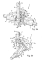
- FIGs 3a and 3b show the switching device 1 in a position in which the reverse gear R is switched.
- the Shift finger 16 To take this position is the Shift finger 16 first by moving the shift shaft 2 along its Swivel axis 2a in the direction of arrow of Figure 3b standing vertically in the picture Double arrow placed in position R '.
- the switching element 7 'in the position X In this position of the shift finger 16 is the switching element 7 'in the position X.
- the shift finger 16 engages in the switching jaw 13 on the switching arm 9 of the switching element 7 'a.
- the barrier sheet 12 dives deeper into the mouth 10c of the bracket 10 and thus continues to block, as previously described, the fifth and sixth gear during the shift and at switched reverse gear.
- the bracket 15 follows the sliding movement of Switching shaft 2 from its blocking position in the direction R until it moves away from the Section 14a of the barrier sheet 14 releases and the switching element 7 'for movement in the switching direction R releases. Subsequently, the shift shaft 2 in the pivoting direction A is pivoted. When pivoting the shift shaft 2 in the Pivoting direction A, the shift finger 16 moves against the inner edge 13a of Wegmaules 13 and forces the switching element 7 'via the switching arm. 9 from the position X in the switching position R. The barrier sheet 14 and thus the Switching element 7 'move along the longitudinal axis 3a unhindered on the Shift shaft 2 to, until the reverse gear R is engaged.
- the barrier bow 14 assumes the function of a stop on the hub 17, the exact location of the switching element 7 'in the position to be switched R secures. At a Gear change or a change to the neutral position of the switching device 1 and thus when removing the reverse gear pivots the stem 2 in the pivoting direction B.
- the shift finger 16 moves against the Inner edge 13b of Wegmaules 13 and moves the element 7 'on the Switching rail 3 in the position X back.
- the bracket 15 is when selecting and switching the reverse gear and in the Switching position R in the entire pivoting range A-B with the switching shaft 2 and the shift finger 16 synchronously either in one or the other of the pivoting directions A or B around the pivot axis 2a free and unhindered in the picture below the barrier sheet 14 through pivotally, without him when panning impeded the barrier sheet 14.
- the bracket 10 is connected to the switching shaft 2 and the Shift finger 16 synchronous either in one or the other of the pivoting directions A or B pivots about the pivot axis 2a and drives at Pivoting with the leg 10a always at the portion 12a and with the Leg 10b always along the section 12b along.
- the swiveling thighs 10a and 10b are always pivoting at least one in the Switching direction V and VI facing point at the section 12a and 12b opposite or are attached to this and lock when dialing and switching the Reverse gear and in the shift position R the fifth and sixth gear in position Y.
- Figure 4a shows the shift finger 16 in a position in which the alley V-VI for alternatively switching the fifth or sixth gear is selected.
- the shift finger 16 first by moving the Switching shaft along its pivot axis 2a in the arrow direction of the figure 3b placed vertically in the image double arrow in the position V-VI, in the the switching element 4 'is in the Y position.
- the shift finger 16 engages in the Wegmaul 11 of the switching element 4 'a. During the movement of the shift shaft.
- the bracket 15 follows the displacement of the switching shaft 2, But remains in the switching direction R seen in the movement space of the Locking piece 14 and thus continues to block, as already described, the Switching element 7 'in the position X during the fifth or sixth gear engaged is switched on and fifth or sixth gear.
- the bracket 10 follows the sliding movement of the switching shaft 2 for selecting the alley V-VI from its blocking position in the direction V-VI, until its legs 10a and 10b of the portion 12a and 12b of the locking piece 12 solve and the Enable switching element 4 'for shifting in the switching direction V and VI. Subsequently, the switching shaft 2 is selectively in the pivoting direction A or B pivoted and switched the fifth or sixth gear.
- the switching device 1 is in a position in which the fifth gear is engaged.
- To take this position is the Shifting finger 16 pivoted in the pivoting direction A.
- the shift finger 16 moves against the inner edge 11a of Wegmaules 11 and forces the switching element 4 'via the switching arm 6 from the position Y in the switching position V.
- a gear change or a Change of the switching element 4 'in the position Y and beyond in the Switching position VI and thus pivots when removing the fifth gear the shift shaft 2 in the pivot direction B.
- the shift finger 16 moves against the inner edge 11b of the Heidelbergmaules 11 and shifts the switching element 4 'on the shift rail 3 in the position Y back or in the position VI.
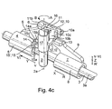
- Figure 4c shows the switching element 4 'in a position in which the sixth gear is switched.
- the shift finger 16 is in the Pivoting direction B pivoted.
- the shift finger 16 moves against the inner edge 11b of Wegmaules 11 and forces the switching element 4 'via the switching arm. 6 from the position Y in the switching position V.
- the shift shaft pivots in the pivoting direction A.
- the shift finger 16 moves against the Inner edge 11a of Wegmaules 11 and moves the switching element 4 'on the shift rail 3 in the position Y back or beyond in the position V.
- the bracket 10 is in the selection and switching of the fifth and sixth gear and in the switching position V and VI in the entire pivoting range A-B with the Shift shaft 2 and the shift finger 16 synchronously either in the one or the other of the pivoting directions A or B around the pivot axis 2 free and freely pivotable over the barrier sheet 12, without pivoting the barrier sheet 12 and thus the switching element 4 'to hinder.
- the coat hanger 15 is synchronous with the shift shaft 2 and the shift finger 16 selectively in the one or the other of the pivoting directions A or B about the pivot axis. 2 swiveling and always moves when pivoting with the connection 15c on the Along section 14a.
- connection 15c is also always at least swinging a pointing in the switching direction R point at the portion 14 a between the shift shaft 2 and the barrier sheet 14 opposite or is present this one.
- the bracket 15 locks when selecting and switching the fifth or sixth gear and in the switching position V or VI the reverse gear in position R.
Landscapes
- Engineering & Computer Science (AREA)
- General Engineering & Computer Science (AREA)
- Mechanical Engineering (AREA)
- Gear-Shifting Mechanisms (AREA)
- Control Of Transmission Device (AREA)
- Arrangement Or Mounting Of Control Devices For Change-Speed Gearing (AREA)
- Keying Circuit Devices (AREA)
- Driving Mechanisms And Operating Circuits Of Arc-Extinguishing High-Tension Switches (AREA)
- Transmitters (AREA)
- Arrangement And Mounting Of Devices That Control Transmission Of Motive Force (AREA)
Description
- Figur 1
- eine Gesamtansicht der Schaltvorrichtung mit Schaltgabeln, durch die ein Rückwärtsgang und aus einer Gasse wahlweise ein fünfter oder sechster Gang schaltbar sind,
- Figur 2a
- die Schaltvorrichtung ohne Schaltgabel mit einem Schaltfinger in einer Neutralstellung sowie mit gleichzeitig gesperrten Gängen,
- Figur 2b
- eine gedrehte Ansicht der Vorrichtung nach Figur 2a,
- Figur 3a
- die Schaltvorrichtung ohne Schaltgabel in einer Schaltstellung, in der der Rückwärtsgang geschaltet und die Gasse für den fünften und sechsten Gang gesperrt ist,
- Figur 3b
- eine gedrehte Ansicht der Schaltvorrichtung nach Figur 3a,
- Figur 4a
- die Schaltvorrichtung ohne Schaftgabeln in einer Stellung, in der die Gasse für den fünften und sechsten Gang gewählt sowie der Rückwärtsgang gesperrt ist,
- Figur 4b
- die Schaltvorrichtung ohne Schaltgabeln in einer Stellung, in der der fünfte Gang geschaltet und der Rückwärtsgang gesperrt ist und
- Figur 4c
- die Schaltvorrichtung in einer Stellung, in der der sechste Gang geschaltet und der Rückwärtsgang gesperrt ist.
- 1
- Schaltvorrichtung
- 2
- Schaltwelle
- 2a
- Schwenkachse
- 3
- Schaltschiene
- 3a
- Längsachse
- 4
- Schaltgabel
- 4'
- Schaltelement
- 5
- Schiebehülse
- 6
- Schaltarm
- 7
- Schaltgabel
- 7'
- Schaltelement
- 8
- Schiebehülse
- 9
- Schaltarm
- 10
- Bügel
- 10a
- Schenkel
- 10b
- Schenkel
- 10c
- Maul
- 10'
- Sperrglied
- 11
- Schaltmaul
- 11a
- Innenflanke
- 11b
- Innenflanke
- 12
- Sperrbogen
- 12'
- Sperrelement
- 12a
- Abschnitt
- 12b
- Abschnitt
- 13
- Schaltmaul
- 13a
- Innenflanke
- 13b
- Innenflanke
- 14
- Sperrbogen
- 14'
- Sperrelement
- 14a
- Abschnitt
- 15
- Bügel
- 15a
- Schenkel
- 15b
- Schenkel
- 15c
- Verbindung
- 15'
- Sperrglied
- 16
- Schaltfinger
- 17
- Nabe
Claims (10)
- Schaltvorrichtung (1) zum Schalten von wenigstens zwei über bewegbare Schaltelemente (4', 7') schaltbaren Gängen eines Schaltgetriebes mit wenigstens einem um eine Schwenkachse (2a) schwenkbaren sowie entlang der Schwenkachse (2a) verschiebbaren Schaltfinger (16), wobei die Schaltvorrichtung (1) mit Sperrgliedern (10',15') versehen ist, die synchron mit dem Schaltfinger (16) um die Schwenkachse (2a) schwenkbar sowie entlang der Schwenkachse (2a) verschiebbar sind, die wahlweise das Schalten mindestens eines der Gänge an einem Schaltelement (4', 7') sperren, wobei die Sperrglieder (10', 15') das jeweils zu sperrende Schaltelement (4', 7') an einem in die zu sperrende Schaltrichtung weisenden Abschnitt (12a, 12b, 14a) des Schaltelementes (4', 7') zumindest dann angreifen, wenn das zu sperrende Schaltelement (4', 7') bestrebt ist, sich in die gesperrte Schaltrichtung zu bewegen, dadurch gekennzeichnet, dass zwei Sperrglieder (10',15') vorgesehen und die Sperrglieder (10', 15') als Bügel (10, 15) ausgebildet sind , wobei mindestens ein Teilabschnitt jedes Bügels (10, 15) um die Schwenkachse (2a) schwenkbar zumindest einem in die Schaltrichtung weisenden Punkt der Oberfläche des Abschnittes (12a, 12b, 14a) in der zu sperrenden Schaltrichtung gegenüberliegt, wobei das eine Sperrglied (10') ein das erste Schaltelement (4') zumindest teilweise übergreifender sowie den Abschnitt (12a) des ersten Schaltelements (4') in Schaltrichtung wenigstens teilweise hintergreifender sowie in die Schaltrichtung unbeweglicher Übergriff ist, und dass der Abschnitt (14a) des zweiten Schaltelements (7') in der Sperrstellung an dem weiteren Sperrglied (15') anliegt.
- Schaltvorrichtung nach Anspruch 1, dadurch gekennzeichnet, dass das Sperrglied (10') ein das Schaltelement (4') zumindest teilweise übergreifender sowie den Abschnitt (12a) wenigstens teilweise in die Schaltrichtung hintergreifender Schenkel (10a) eines zweischenkeligen Bügels (10) ist.
- Schaltvorrichtung nach Anspruch 1, dadurch gekennzeichnet, dass der Bügel (15) zweischenkelig ausgebildet ist und mit den freien Enden seiner Schenkel (15a, 15b) zur Schwenkachse (2a) weist, wobei der Bügel (15) mit einem von der Schwenkachse (2a) weggewandten Teilabschnitt einer zur Schwenkachse (2a) ausgerichteten Verbindung (15c) seiner Schenkel (15a, 15b) zumindest teilweise an dem Abschnitt (14a) anliegt.
- Schaltvorrichtung nach Anspruch 1, , dadurch gekennzeichnet, dass die Schaltvorrichtung (1) eine Schaltwelle (2) aufweist, wobei die Längsmittelachse der Schaltwelle (2) die Schwenkachse (2a) ist und dass die Bügel (10, 15) um die Längsmittelachse schwenkbar an der Schaltwelle (2) befestigt sind.
- Schaltvorrichtung nach Anspruch 1, dadurch gekennzeichnet, dass das Schaltelement (4', 7') eine Schaltgabel (4, 7) für das Schalten zumindestens eines Ganges aufweist.
- Schaltvorrichtung nach Anspruch 1, mit wenigstens einem zum wahlweisen Schalten von zwei Gängen in zwei Schaltrichtungen bewegbaren Schaltelement (7'), dadurch gekennzeichnet, dass das Schaltelement (7') eine Schaltgabel (7) für das Schalten von zwei Gängen aufweist.
- Schaltvorrichtung nach Anspruch 1, dadurch gekennzeichnet, dass das Schaltelement (7') zum wahlweisen Schalten von zwei Gängen in zwei Schaltrichtungen bewegbar ist und mittels des Sperrgliedes (15') in beide Schaltrichtungen unbeweglich sperrbar ist, wobei das Sperrglied (15') ein das Schaltelement (7') zumindest teilweise übergreifender sowie den jeweiligen in Schaltrichtung weisenden Abschnitt (14a) mit jeweils einem Schenkel (15a, 15b) wenigstens teilweise in Schaltrichtung hintergreifender zweischenkeliger Bügel (15) ist.
- Schaltvorrichtung nach Anspruch 1, dadurch gekennzeichnet, dass das erste Schaltelement (4') zum wahlweisen Schalten von zwei Gängen in zwei Schaltrichtungen bewegbar und mittels eines ersten Sperrgliedes (10') in beide Schaltrichtungen unbeweglich sperrbar ist, wobei das Sperrglied (10') ein das Schaltelement (4') zumindest teilweise übergreifender sowie den jeweiligen in Schaltrichtung weisenden Abschnitt (12a, 12b) mit jeweils einem Schenkel (10a, 10b) wenigstens teilweise in Schaltrichtung hintergreifender zweischenkeliger Bügel (10) ist und dass das in wenigstens eine Schaltrichtung bewegbare zweite Schaltelement (7') zum Schalten wenigstens eines dritten Ganges mittels eines zweiten Sperrgliedes (15') in eine Schaltrichtung unbeweglich sperrbar ist, wobei das zweite Sperrglied (15') ein zweischenkelig ausgebildeter Bügel (15) ist und mit den freien Enden seiner Schenkel (15a, 15b) zur Schwenkachse (2a) weist und wobei der Bügel (15) mit seiner von der Schwenkachse (2a) weg gewandten Seite der Verbindung (15c) seiner Schenkel (15a, 15b) an dem Abschnitt des zweiten Schaltelementes (7') anliegt.
- Schaltvorrichtung nach Anspruch 8, dadurch gekennzeichnet, dass die Schaltvorrichtung (1) eine Schaltwelle (2) aufweist, wobei die Längsmittelachse der Schaltwelle (2) die Schwenkachse (2a) ist und dass die Bügel (10, 15) um die Längsmittelachse schwenkbar an der Schaltwelle (2) befestigt sind.
- Schaltvorrichtung nach Anspruch 1, 2 oder 3, dadurch gekennzeichnet, dass der Bügel (10, 15) ein Stanzteil aus Stahl ist.
Applications Claiming Priority (3)
| Application Number | Priority Date | Filing Date | Title |
|---|---|---|---|
| DE10160859 | 2001-12-12 | ||
| DE10160859A DE10160859A1 (de) | 2001-12-12 | 2001-12-12 | Schaltvorrichtung zum Schalten von wenigstens zwei schaltbaren Gängen eines Schaltgetriebes |
| PCT/EP2002/012648 WO2003050439A2 (de) | 2001-12-12 | 2002-11-13 | Schaltvorrichtung zum schalten von wenigstens zwei schaltbaren gängen eines schaltgetriebes |
Publications (2)
| Publication Number | Publication Date |
|---|---|
| EP1454083A2 EP1454083A2 (de) | 2004-09-08 |
| EP1454083B1 true EP1454083B1 (de) | 2005-10-12 |
Family
ID=7708825
Family Applications (1)
| Application Number | Title | Priority Date | Filing Date |
|---|---|---|---|
| EP02804572A Expired - Lifetime EP1454083B1 (de) | 2001-12-12 | 2002-11-13 | Schaltvorrichtung zum schalten von wenigstens zwei schaltbaren gängen eines schaltgetriebes |
Country Status (6)
| Country | Link |
|---|---|
| EP (1) | EP1454083B1 (de) |
| AT (1) | ATE306631T1 (de) |
| AU (1) | AU2002366540A1 (de) |
| BR (1) | BR0207198A (de) |
| DE (2) | DE10160859A1 (de) |
| WO (1) | WO2003050439A2 (de) |
Families Citing this family (4)
| Publication number | Priority date | Publication date | Assignee | Title |
|---|---|---|---|---|
| DE102007013929A1 (de) * | 2007-03-23 | 2008-09-25 | Zf Friedrichshafen Ag | Anordnung einer Schaltschwinge in einem Getriebe |
| FR2915261B1 (fr) * | 2007-04-19 | 2009-07-03 | Peugeot Citroen Automobiles Sa | Dispositif de commande interne de boite de vitesses. |
| DE102007042805A1 (de) * | 2007-09-07 | 2009-03-12 | Schaeffler Kg | Schaltvorrichtung |
| CN104514877B (zh) * | 2014-12-25 | 2017-02-22 | 长城汽车股份有限公司 | 倒挡锁止机构及具有其的变速器、汽车 |
Family Cites Families (8)
| Publication number | Priority date | Publication date | Assignee | Title |
|---|---|---|---|---|
| AT88856B (de) * | 1920-02-17 | 1922-06-26 | Oesterr Daimler Motoren Ag | Schaltwerk, insbesondere für Motorfahrzeuge u. dgl. |
| DE1157490B (de) * | 1959-10-27 | 1963-11-14 | Georg Kirmair | Vom Wechselgetriebe getrennte Schalt- und Schaltsperrvorrichtung fuer Kraftfahrzeuge mit Zahnraederwechselgetriebe |
| CS177427B1 (en) * | 1973-06-14 | 1977-07-29 | Frantisek Plenar | Change-speed gearing control device for gearboxws wiyh gear change |
| JPS5975964U (ja) * | 1982-11-15 | 1984-05-23 | トヨタ自動車株式会社 | 手動変速機におけるリバ−スギヤ鳴り防止装置 |
| JPH05248539A (ja) * | 1992-03-09 | 1993-09-24 | Kubota Corp | 変速装置の変速操作構造 |
| DE4242456C2 (de) * | 1992-12-16 | 1995-11-30 | Daimler Benz Ag | Lagerung eines Handschalthebels einer Schaltvorrichtung eines Zahnräderwechselgetriebes |
| DE29814943U1 (de) * | 1998-02-13 | 1999-05-27 | Kochendörfer & Kiep Stanz- und Feinstanzwerk GmbH & Co. KG, 78467 Konstanz | Getriebe |
| DE10011272C1 (de) * | 2000-03-08 | 2001-08-23 | Daimler Chrysler Ag | Schalt- und Sperrvorrichtung eines Zahnräder-Wechselgetriebes |
-
2001
- 2001-12-12 DE DE10160859A patent/DE10160859A1/de not_active Withdrawn
-
2002
- 2002-11-13 BR BR0207198-3A patent/BR0207198A/pt active Search and Examination
- 2002-11-13 DE DE50204561T patent/DE50204561D1/de not_active Expired - Lifetime
- 2002-11-13 AT AT02804572T patent/ATE306631T1/de not_active IP Right Cessation
- 2002-11-13 WO PCT/EP2002/012648 patent/WO2003050439A2/de not_active Ceased
- 2002-11-13 AU AU2002366540A patent/AU2002366540A1/en not_active Abandoned
- 2002-11-13 EP EP02804572A patent/EP1454083B1/de not_active Expired - Lifetime
Also Published As
| Publication number | Publication date |
|---|---|
| AU2002366540A8 (en) | 2003-06-23 |
| AU2002366540A1 (en) | 2003-06-23 |
| ATE306631T1 (de) | 2005-10-15 |
| WO2003050439A3 (de) | 2003-09-04 |
| DE10160859A1 (de) | 2003-06-26 |
| DE50204561D1 (de) | 2005-11-17 |
| EP1454083A2 (de) | 2004-09-08 |
| WO2003050439A2 (de) | 2003-06-19 |
| BR0207198A (pt) | 2004-03-09 |
Similar Documents
| Publication | Publication Date | Title |
|---|---|---|
| WO2004046588A1 (de) | Schaltvorrichtung für ein getriebe | |
| DE102008028619A1 (de) | Schaltvorrichtung für ein Getriebe | |
| DE10249074B4 (de) | Schaltvorrichtung für ein automatisches Getriebe | |
| EP0699853B1 (de) | Betätigungseinrichtung zum Steuern des Gangwechsels eines Kraftfahrzeuggetriebes | |
| EP1454083B1 (de) | Schaltvorrichtung zum schalten von wenigstens zwei schaltbaren gängen eines schaltgetriebes | |
| EP1714057B1 (de) | Einstangenschaltvorrichtung an einem schaltgetriebe | |
| DE102007035304A1 (de) | Schalteinrichtung für ein mehrgängiges Zahnräderwechselgetriebe eines Kraftfahrzeuges | |
| DE102006039955B4 (de) | Rückwärts- und Parksperrvorrichtung in einem Getriebesteuermechanismus | |
| DE10151467A1 (de) | Schaltgetriebe mit Verriegelungseinrichtung zur Verriegelung einzelner Gänge | |
| DE102004060232A1 (de) | Elektrische Schalteinrichtung für ein automatisiertes Getriebe | |
| WO2013030232A1 (de) | Schaltvorrichtung | |
| DE102004051421A1 (de) | Vorrichtung zum Schalten zweier Gangräder mittels einer aus einer neutralen Stellung in Richtung der Gangräder verschiebbaren Schiebemuffe | |
| EP2619485B1 (de) | Schaltanordnung eines zahnräderwechselgetriebes | |
| DE102010036389B4 (de) | Schaltanordnung für ein Kraftfahrzeug | |
| DE60006457T2 (de) | Getriebe kompakter Bauart mit Schwenkfüssen zur Betätigung von Schaltgabeln | |
| DE10204232B4 (de) | Sperreinrichtung | |
| EP1245872B1 (de) | Schaltvorrichtung für ein Zahnräderwechselgetriebe, insbesondere für Kraftfahrzeuge | |
| DE2510154A1 (de) | Schalteinrichtung fuer wechselgetriebe von kraftfahrzeugen | |
| EP1642054B1 (de) | Schaltvorrichtung für ein getriebe | |
| DE102013224741A1 (de) | Manuell betätigbare Schalteinrichtung eines Zahnräderwechselgetriebes | |
| DE19853584A1 (de) | Schaltvorrichtung für ein Zahnräderwechselgetriebe | |
| EP1310707B1 (de) | Schaltvorrichtung für ein Wechselgetriebe und Verfahren zur Bewegung und Führung von Schaltgabeln in einem Wechselgetriebe | |
| DE10351131A1 (de) | Schalteinrichtung für ein mehrstufiges Schaltgetriebe | |
| EP1333203B1 (de) | Sperreinrichtung | |
| DE1130300B (de) | Schaltvorrichtung fuer ein vielgaengiges Kraftfahrzeugwechselgetriebe |
Legal Events
| Date | Code | Title | Description |
|---|---|---|---|
| PUAI | Public reference made under article 153(3) epc to a published international application that has entered the european phase |
Free format text: ORIGINAL CODE: 0009012 |
|
| 17P | Request for examination filed |
Effective date: 20040603 |
|
| AK | Designated contracting states |
Kind code of ref document: A2 Designated state(s): AT BE BG CH CY CZ DE DK EE ES FI FR GB GR IE IT LI LU MC NL PT SE SK TR |
|
| AX | Request for extension of the european patent |
Extension state: AL LT LV MK RO SI |
|
| 17Q | First examination report despatched |
Effective date: 20040915 |
|
| GRAP | Despatch of communication of intention to grant a patent |
Free format text: ORIGINAL CODE: EPIDOSNIGR1 |
|
| GRAS | Grant fee paid |
Free format text: ORIGINAL CODE: EPIDOSNIGR3 |
|
| GRAA | (expected) grant |
Free format text: ORIGINAL CODE: 0009210 |
|
| AK | Designated contracting states |
Kind code of ref document: B1 Designated state(s): AT BE BG CH CY CZ DE DK EE ES FI FR GB GR IE IT LI LU MC NL PT SE SK TR |
|
| PG25 | Lapsed in a contracting state [announced via postgrant information from national office to epo] |
Ref country code: EE Free format text: LAPSE BECAUSE OF FAILURE TO SUBMIT A TRANSLATION OF THE DESCRIPTION OR TO PAY THE FEE WITHIN THE PRESCRIBED TIME-LIMIT Effective date: 20051012 Ref country code: NL Free format text: LAPSE BECAUSE OF FAILURE TO SUBMIT A TRANSLATION OF THE DESCRIPTION OR TO PAY THE FEE WITHIN THE PRESCRIBED TIME-LIMIT Effective date: 20051012 Ref country code: SK Free format text: LAPSE BECAUSE OF FAILURE TO SUBMIT A TRANSLATION OF THE DESCRIPTION OR TO PAY THE FEE WITHIN THE PRESCRIBED TIME-LIMIT Effective date: 20051012 Ref country code: FI Free format text: LAPSE BECAUSE OF FAILURE TO SUBMIT A TRANSLATION OF THE DESCRIPTION OR TO PAY THE FEE WITHIN THE PRESCRIBED TIME-LIMIT Effective date: 20051012 Ref country code: IE Free format text: LAPSE BECAUSE OF FAILURE TO SUBMIT A TRANSLATION OF THE DESCRIPTION OR TO PAY THE FEE WITHIN THE PRESCRIBED TIME-LIMIT Effective date: 20051012 Ref country code: TR Free format text: LAPSE BECAUSE OF FAILURE TO SUBMIT A TRANSLATION OF THE DESCRIPTION OR TO PAY THE FEE WITHIN THE PRESCRIBED TIME-LIMIT Effective date: 20051012 |
|
| REG | Reference to a national code |
Ref country code: GB Ref legal event code: FG4D Free format text: NOT ENGLISH |
|
| REG | Reference to a national code |
Ref country code: CH Ref legal event code: EP |
|
| REG | Reference to a national code |
Ref country code: IE Ref legal event code: FG4D Free format text: LANGUAGE OF EP DOCUMENT: GERMAN |
|
| PG25 | Lapsed in a contracting state [announced via postgrant information from national office to epo] |
Ref country code: CY Free format text: LAPSE BECAUSE OF FAILURE TO SUBMIT A TRANSLATION OF THE DESCRIPTION OR TO PAY THE FEE WITHIN THE PRESCRIBED TIME-LIMIT Effective date: 20051113 Ref country code: AT Free format text: LAPSE BECAUSE OF NON-PAYMENT OF DUE FEES Effective date: 20051113 |
|
| REF | Corresponds to: |
Ref document number: 50204561 Country of ref document: DE Date of ref document: 20051117 Kind code of ref document: P |
|
| PG25 | Lapsed in a contracting state [announced via postgrant information from national office to epo] |
Ref country code: BE Free format text: LAPSE BECAUSE OF NON-PAYMENT OF DUE FEES Effective date: 20051130 Ref country code: MC Free format text: LAPSE BECAUSE OF NON-PAYMENT OF DUE FEES Effective date: 20051130 |
|
| PG25 | Lapsed in a contracting state [announced via postgrant information from national office to epo] |
Ref country code: LU Free format text: LAPSE BECAUSE OF NON-PAYMENT OF DUE FEES Effective date: 20051212 |
|
| PG25 | Lapsed in a contracting state [announced via postgrant information from national office to epo] |
Ref country code: GR Free format text: LAPSE BECAUSE OF FAILURE TO SUBMIT A TRANSLATION OF THE DESCRIPTION OR TO PAY THE FEE WITHIN THE PRESCRIBED TIME-LIMIT Effective date: 20060112 Ref country code: BG Free format text: LAPSE BECAUSE OF FAILURE TO SUBMIT A TRANSLATION OF THE DESCRIPTION OR TO PAY THE FEE WITHIN THE PRESCRIBED TIME-LIMIT Effective date: 20060112 Ref country code: DK Free format text: LAPSE BECAUSE OF FAILURE TO SUBMIT A TRANSLATION OF THE DESCRIPTION OR TO PAY THE FEE WITHIN THE PRESCRIBED TIME-LIMIT Effective date: 20060112 |
|
| PG25 | Lapsed in a contracting state [announced via postgrant information from national office to epo] |
Ref country code: ES Free format text: LAPSE BECAUSE OF FAILURE TO SUBMIT A TRANSLATION OF THE DESCRIPTION OR TO PAY THE FEE WITHIN THE PRESCRIBED TIME-LIMIT Effective date: 20060123 |
|
| REG | Reference to a national code |
Ref country code: SE Ref legal event code: TRGR |
|
| GBT | Gb: translation of ep patent filed (gb section 77(6)(a)/1977) |
Effective date: 20060130 |
|
| PG25 | Lapsed in a contracting state [announced via postgrant information from national office to epo] |
Ref country code: PT Free format text: LAPSE BECAUSE OF FAILURE TO SUBMIT A TRANSLATION OF THE DESCRIPTION OR TO PAY THE FEE WITHIN THE PRESCRIBED TIME-LIMIT Effective date: 20060313 |
|
| NLV1 | Nl: lapsed or annulled due to failure to fulfill the requirements of art. 29p and 29m of the patents act | ||
| RAP2 | Party data changed (patent owner data changed or rights of a patent transferred) |
Owner name: SCHAEFFLER KG |
|
| REG | Reference to a national code |
Ref country code: IE Ref legal event code: FD4D |
|
| ET | Fr: translation filed | ||
| PLBE | No opposition filed within time limit |
Free format text: ORIGINAL CODE: 0009261 |
|
| STAA | Information on the status of an ep patent application or granted ep patent |
Free format text: STATUS: NO OPPOSITION FILED WITHIN TIME LIMIT |
|
| 26N | No opposition filed |
Effective date: 20060713 |
|
| PG25 | Lapsed in a contracting state [announced via postgrant information from national office to epo] |
Ref country code: LI Free format text: LAPSE BECAUSE OF NON-PAYMENT OF DUE FEES Effective date: 20061130 Ref country code: CH Free format text: LAPSE BECAUSE OF NON-PAYMENT OF DUE FEES Effective date: 20061130 |
|
| REG | Reference to a national code |
Ref country code: CH Ref legal event code: PFA Owner name: SCHAEFFLER KG Free format text: INA-SCHAEFFLER KG#INDUSTRIESTRASSE 1 - 3#91074 HERZOGENAURACH (DE) -TRANSFER TO- SCHAEFFLER KG#INDUSTRIESTRASSE 1 - 3#91074 HERZOGENAURACH (DE) Ref country code: CH Ref legal event code: NV Representative=s name: TROESCH SCHEIDEGGER WERNER AG |
|
| REG | Reference to a national code |
Ref country code: CH Ref legal event code: PL |
|
| BERE | Be: lapsed |
Owner name: INA-SCHAEFFLER K.G. Effective date: 20051130 |
|
| PGFP | Annual fee paid to national office [announced via postgrant information from national office to epo] |
Ref country code: CZ Payment date: 20081106 Year of fee payment: 7 |
|
| PGFP | Annual fee paid to national office [announced via postgrant information from national office to epo] |
Ref country code: SE Payment date: 20081107 Year of fee payment: 7 Ref country code: IT Payment date: 20081125 Year of fee payment: 7 |
|
| PGFP | Annual fee paid to national office [announced via postgrant information from national office to epo] |
Ref country code: FR Payment date: 20081112 Year of fee payment: 7 |
|
| PGFP | Annual fee paid to national office [announced via postgrant information from national office to epo] |
Ref country code: GB Payment date: 20081112 Year of fee payment: 7 |
|
| EUG | Se: european patent has lapsed | ||
| GBPC | Gb: european patent ceased through non-payment of renewal fee |
Effective date: 20091113 |
|
| REG | Reference to a national code |
Ref country code: FR Ref legal event code: ST Effective date: 20100730 |
|
| PG25 | Lapsed in a contracting state [announced via postgrant information from national office to epo] |
Ref country code: CZ Free format text: LAPSE BECAUSE OF NON-PAYMENT OF DUE FEES Effective date: 20091113 |
|
| PG25 | Lapsed in a contracting state [announced via postgrant information from national office to epo] |
Ref country code: FR Free format text: LAPSE BECAUSE OF NON-PAYMENT OF DUE FEES Effective date: 20091130 |
|
| PG25 | Lapsed in a contracting state [announced via postgrant information from national office to epo] |
Ref country code: GB Free format text: LAPSE BECAUSE OF NON-PAYMENT OF DUE FEES Effective date: 20091113 |
|
| PG25 | Lapsed in a contracting state [announced via postgrant information from national office to epo] |
Ref country code: IT Free format text: LAPSE BECAUSE OF NON-PAYMENT OF DUE FEES Effective date: 20091113 |
|
| PG25 | Lapsed in a contracting state [announced via postgrant information from national office to epo] |
Ref country code: SE Free format text: LAPSE BECAUSE OF NON-PAYMENT OF DUE FEES Effective date: 20091114 |
|
| REG | Reference to a national code |
Ref country code: DE Ref legal event code: R081 Ref document number: 50204561 Country of ref document: DE Owner name: SCHAEFFLER TECHNOLOGIES AG & CO. KG, DE Free format text: FORMER OWNER: SCHAEFFLER TECHNOLOGIES GMBH & CO. KG, 91074 HERZOGENAURACH, DE Effective date: 20120828 Ref country code: DE Ref legal event code: R081 Ref document number: 50204561 Country of ref document: DE Owner name: SCHAEFFLER TECHNOLOGIES GMBH & CO. KG, DE Free format text: FORMER OWNER: SCHAEFFLER TECHNOLOGIES GMBH & CO. KG, 91074 HERZOGENAURACH, DE Effective date: 20120828 |
|
| REG | Reference to a national code |
Ref country code: DE Ref legal event code: R081 Ref document number: 50204561 Country of ref document: DE Owner name: SCHAEFFLER TECHNOLOGIES GMBH & CO. KG, DE Free format text: FORMER OWNER: SCHAEFFLER TECHNOLOGIES AG & CO. KG, 91074 HERZOGENAURACH, DE Effective date: 20140214 Ref country code: DE Ref legal event code: R081 Ref document number: 50204561 Country of ref document: DE Owner name: SCHAEFFLER TECHNOLOGIES AG & CO. KG, DE Free format text: FORMER OWNER: SCHAEFFLER TECHNOLOGIES AG & CO. KG, 91074 HERZOGENAURACH, DE Effective date: 20140214 |
|
| REG | Reference to a national code |
Ref country code: DE Ref legal event code: R081 Ref document number: 50204561 Country of ref document: DE Owner name: SCHAEFFLER TECHNOLOGIES AG & CO. KG, DE Free format text: FORMER OWNER: SCHAEFFLER TECHNOLOGIES GMBH & CO. KG, 91074 HERZOGENAURACH, DE Effective date: 20150213 |
|
| PGFP | Annual fee paid to national office [announced via postgrant information from national office to epo] |
Ref country code: DE Payment date: 20180131 Year of fee payment: 16 |
|
| REG | Reference to a national code |
Ref country code: DE Ref legal event code: R119 Ref document number: 50204561 Country of ref document: DE |
|
| PG25 | Lapsed in a contracting state [announced via postgrant information from national office to epo] |
Ref country code: DE Free format text: LAPSE BECAUSE OF NON-PAYMENT OF DUE FEES Effective date: 20190601 |
|
| P01 | Opt-out of the competence of the unified patent court (upc) registered |
Effective date: 20230522 |