EP1453682B1 - Reinigung von stoffstrahlspritzköpfen - Google Patents
Reinigung von stoffstrahlspritzköpfen Download PDFInfo
- Publication number
- EP1453682B1 EP1453682B1 EP02803845A EP02803845A EP1453682B1 EP 1453682 B1 EP1453682 B1 EP 1453682B1 EP 02803845 A EP02803845 A EP 02803845A EP 02803845 A EP02803845 A EP 02803845A EP 1453682 B1 EP1453682 B1 EP 1453682B1
- Authority
- EP
- European Patent Office
- Prior art keywords
- matter
- delivering
- cleaning
- absorbing member
- displacement means
- Prior art date
- Legal status (The legal status is an assumption and is not a legal conclusion. Google has not performed a legal analysis and makes no representation as to the accuracy of the status listed.)
- Expired - Lifetime
Links
- 238000004140 cleaning Methods 0.000 title claims abstract description 101
- 239000000463 material Substances 0.000 title abstract description 125
- 239000007921 spray Substances 0.000 title abstract description 5
- 238000006073 displacement reaction Methods 0.000 claims abstract description 27
- 238000000034 method Methods 0.000 claims abstract description 14
- 238000010521 absorption reaction Methods 0.000 claims abstract description 4
- 238000010926 purge Methods 0.000 claims description 46
- 238000007790 scraping Methods 0.000 claims description 17
- 238000005507 spraying Methods 0.000 claims description 13
- 239000000126 substance Substances 0.000 claims description 4
- 230000033001 locomotion Effects 0.000 claims description 3
- 230000002068 genetic effect Effects 0.000 claims description 2
- 239000007788 liquid Substances 0.000 claims description 2
- 238000007641 inkjet printing Methods 0.000 claims 1
- 230000002745 absorbent Effects 0.000 abstract description 38
- 239000002250 absorbent Substances 0.000 abstract description 38
- YFXPPSKYMBTNAV-UHFFFAOYSA-N bensultap Chemical compound C=1C=CC=CC=1S(=O)(=O)SCC(N(C)C)CSS(=O)(=O)C1=CC=CC=C1 YFXPPSKYMBTNAV-UHFFFAOYSA-N 0.000 description 11
- 238000010586 diagram Methods 0.000 description 5
- 230000008569 process Effects 0.000 description 5
- 239000000758 substrate Substances 0.000 description 5
- 230000004913 activation Effects 0.000 description 4
- 238000004519 manufacturing process Methods 0.000 description 4
- 210000000056 organ Anatomy 0.000 description 3
- 238000007639 printing Methods 0.000 description 3
- 239000006096 absorbing agent Substances 0.000 description 2
- 238000004043 dyeing Methods 0.000 description 2
- 230000000763 evoking effect Effects 0.000 description 2
- 239000000976 ink Substances 0.000 description 2
- 230000007246 mechanism Effects 0.000 description 2
- 230000000737 periodic effect Effects 0.000 description 2
- 238000003825 pressing Methods 0.000 description 2
- 238000009825 accumulation Methods 0.000 description 1
- 230000005540 biological transmission Effects 0.000 description 1
- 239000011538 cleaning material Substances 0.000 description 1
- 230000003749 cleanliness Effects 0.000 description 1
- 150000001875 compounds Chemical class 0.000 description 1
- 238000001514 detection method Methods 0.000 description 1
- 230000009977 dual effect Effects 0.000 description 1
- 230000000694 effects Effects 0.000 description 1
- 239000012535 impurity Substances 0.000 description 1
- 239000006193 liquid solution Substances 0.000 description 1
- 230000003287 optical effect Effects 0.000 description 1
- 238000007665 sagging Methods 0.000 description 1
- 238000007789 sealing Methods 0.000 description 1
- 238000003892 spreading Methods 0.000 description 1
- 230000007480 spreading Effects 0.000 description 1
- 238000011144 upstream manufacturing Methods 0.000 description 1
Images



Classifications
-
- B—PERFORMING OPERATIONS; TRANSPORTING
- B41—PRINTING; LINING MACHINES; TYPEWRITERS; STAMPS
- B41J—TYPEWRITERS; SELECTIVE PRINTING MECHANISMS, i.e. MECHANISMS PRINTING OTHERWISE THAN FROM A FORME; CORRECTION OF TYPOGRAPHICAL ERRORS
- B41J2/00—Typewriters or selective printing mechanisms characterised by the printing or marking process for which they are designed
- B41J2/005—Typewriters or selective printing mechanisms characterised by the printing or marking process for which they are designed characterised by bringing liquid or particles selectively into contact with a printing material
- B41J2/01—Ink jet
- B41J2/135—Nozzles
- B41J2/165—Prevention or detection of nozzle clogging, e.g. cleaning, capping or moistening for nozzles
- B41J2/16517—Cleaning of print head nozzles
- B41J2/16535—Cleaning of print head nozzles using wiping constructions
-
- B—PERFORMING OPERATIONS; TRANSPORTING
- B05—SPRAYING OR ATOMISING IN GENERAL; APPLYING FLUENT MATERIALS TO SURFACES, IN GENERAL
- B05B—SPRAYING APPARATUS; ATOMISING APPARATUS; NOZZLES
- B05B15/00—Details of spraying plant or spraying apparatus not otherwise provided for; Accessories
- B05B15/50—Arrangements for cleaning; Arrangements for preventing deposits, drying-out or blockage; Arrangements for detecting improper discharge caused by the presence of foreign matter
- B05B15/52—Arrangements for cleaning; Arrangements for preventing deposits, drying-out or blockage; Arrangements for detecting improper discharge caused by the presence of foreign matter for removal of clogging particles
Definitions
- the invention relates to the cleaning of jet heads of material as well as machines and manufacturing equipment equipped with self-cleaning material jet heads.
- material jet heads is understood to mean either ink-jet dye printing heads or liquid-spraying heads, viscous or powdery products.
- the fields to which the invention applies aim, beyond the dyeing with inks, the jet of material having medical, biological, genetic, chemical, acoustic, insulating or electrically conductive functions or properties, or the like.
- the document WO-A-9919900 shows various uses of the material jet, apart from printing.
- Devices employing material jet heads are used to spray drops of material onto a substrate so as to form a three-dimensional image or structure.
- the document FR-A-2790421 filed in the name of the applicant, describes a graphic material jet machine provided with at least one inkjet head.
- This document provides an example of using material jet heads for pattern printing on a medium such as a smart card.
- the document US 5449754 describes a process for producing chemical compounds by projecting drops of various liquid solutions onto a substrate.
- This document provides an example of using material jet heads for an application in chemistry.
- the methods and devices for projecting droplets of material have the characteristic of being sensitive to the fouling of the material outlet orifices.
- these orifices have a diameter of the order of a few tens of microns and, therefore, the smallest impurity can disturb the jet of material.
- This solution has a number of disadvantages including the difficulty of sealing the entire container-ports, the container being removable. On the other hand, the risk of coulure -is important in the case of a jet head of material that can take various positions.
- the invention overcomes these disadvantages, in particular by providing a simple cleaning to ensure a perfect cleanliness consistent with the requirements of the jet of precision material and / or high rates without resorting to a complex and expensive mechanism.
- the material jet head may belong to the group consisting of ink jet print heads, viscous liquid spray heads, dispensing systems and the like.
- the projected material may belong to the group formed by dyeing, medical, biological substances; electrically conductive, electrically conductive, or similar.
- the evoked material exit device may comprise at least one material outlet.
- the absorbent member may be of generally flat shape and be arranged in the cleaning plane, facing the material outlet device.
- the scraper member may be arranged such that the absorbent member is positioned between the material outlet device and the scraper member.
- step c) the cleaning member is formed by pressing the scraper member and the absorbent member against the material outlet device.
- the absorbent member may be of generally flat shape and be arranged in the cleaning plane, facing the device of a kind of material.
- the scraper member may be arranged such that the absorbent member is positioned between the material outlet device and the scraper member.
- the first displacement means may comprise a slideway allowing the translation of the scraper member in the direction of displacement of the absorbent member.
- the second moving means may comprise an electromagnet actuator.
- the absorbent member is in the form of a strip of absorbent material and the third moving means comprise a take-up spool and a reel and two guide spindles, both of these spools being able to cooperate to scroll the spool. absorbent material ribbon between the two guide pins.
- the fourth moving means may comprise at least one slideway allowing translation in the direction of elevation of at least one of the guide axes.
- the fourth moving means may comprise at least one eccentric allowing the translation in the direction of elevation of at least one of the guide axes.
- the purge means are capable, during the purge cycle of the cleaning system, of controlling the expulsion of material continuously from the material outlet device for a predetermined period of time.
- control means of the material jet function are capable, during the jet cycle of the cleaning system, of controlling the specific execution of jets of material through the material outlet device, regular intervals during the duration of the jet cycle.
- the longitudinal direction is represented by the X axis
- the transverse direction is represented by the Y axis
- the elevation direction is represented by the Z axis.
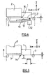
- the figure 1 schematically represents a material jet machine seen from the side, equipped with a cleaning system according to the invention. Only the elements involved in the cleaning phases have been represented.
- the machine comprises a material jet jet head 1 fed by a material tank 2.
- This head is movable in the transverse direction Y so as to be able to reach the material jet zones of the machine and to be able to position itself above the cleaning system during the cleaning phases as shown on the Figures 1 to 5 .
- the cleaning system is fixed on one side of the material jet machine, on the transverse displacement path (in the transverse direction Y) of the material jet head.
- the material jet head includes a substantially planar nozzle plate 11 including a plurality of material outlet ports.
- the cleaning system comprises a ribbon 3 of absorbent material of greater width than that of the jet head of material 1 (see figure 3 ) and can scroll under it by fraction of a reel unwinder 4 and a reel 5, the latter being set in motion by a motor 6 and via transmission means.
- the ribbon 3 may have a width (in the transverse direction Y) of 80 mm and a thickness of 0.25 mm, a new take-up reel 4 may have a diameter of 70 mm corresponding to a reel diameter of the reel 5 full of 75 mm , the spacing of the coils 4, 5 then being 54 mm.
- the positioning and guiding of the ribbon 3 is done by two rollers 7, 8 rotatably mounted and arranged parallel to the transverse direction Y so as to maintain substantially flat a portion of the ribbon 3 stretched under the jet head of material 1.
- rollers 7, 8 forming guide shafts are also movable in the direction of elevation. They are mounted on translation means in the direction of elevation Z such as slideways or eccentrics, a control device of these translation means then allowing positioning in the direction of elevation Z of the ribbon portion. 3 located between the axes 7, 8.
- the rotation of the axis of the unwinding roll 4 is controlled with respect to the control of the motor 6 so as to provide resistance to the unwinding of the spool 4 to maintain the tension of the ribbon 3 between the guide pins 7, 8 and to ensure a booster effect.
- the rotation of the coils 4, 5 is controlled, for example by means of a coding wheel, so as to detect any incident such as the breaking of the ribbon 3 or the failure of the motor 6, the purging operation not being executed in case of detection of such an incentive.
- the motor 6 also has a command for controlling the speed of rotation of the spool 5 so that the running speed of the ribbon 3 remains constant regardless of the sliver of tape 3 coiled on the reel 5, the information concerning the instantaneous diameter of the reel 5 being given by any appropriate means, for example a rangefinder, a mechanical pad or a potentiometer.
- the roller mechanism 4, 5 described allows the ribbon 3 to be passed under the nozzle plate 11 in a continuous manner, as shown diagrammatically in FIG. figure 2 .
- a doctor blade 9 mounted on a slide 10 allowing the doctor blade 9 to translate along the longitudinal direction X over a distance greater than the length ( in the longitudinal direction X) of the nozzle plate 11.
- the doctor blade 9 extends transversely to the material jet head 1, in the transverse direction Y over at least a width equal to that of the nozzle plate 11.
- the doctor blade 9 is also controlled by an actuator 12 with an electromagnet fixed on the slide 10 and able to press the doctor blade 9 against the nozzle plate 11 when it is actuated, the doctor blade 9 being kept away from the nozzle plate 11 by a spring 13 when the actuator 12 is in the idle state.
- the material jet head is also provided with a purge device arranged to pressurize the material reservoir 2 and thus force the material to exit continuously through the material outlet orifices, thus ensuring a purge of the material circuit. jet of matter.
- the described cleaning system operates as indicated below.
- the material jet head moves parallel to the transverse direction Y, above the substrate to be printed,
- the material jet head is placed at the end of travel of the transverse direction Y so as to be positioned on the machine side where is disposed the cleaning system, above the ribbon 3 (such that represented on the figure 1 ).
- the cleaning system is in the idle state, that is to say that the blade 9 is kept spaced apart from the ribbon 3 by the spring 13, that the guide pins 7, 8 are arranged in the direction of Z elevation so as to maintain the ribbon portion 3 located between them at a distance of about 2 mm from the nozzle plate 11.
- the material produced by the purging operation is thus absorbed by the ribbon 3 traveling at a speed sufficient for no sagging to occur.
- the ribbon 3 passes under the nozzle plate 11 and the doctor blade 9, which is mounted in free translation on the slide 10 and which is in contact with the ribbon 3, is then driven in translation so that the cleaning member travels the entire length (along X) of the nozzle plate 11 thus ensuring optimum cleaning.
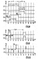
- the figure 7 represents another cleaning sequence comprising first a purge cycle P as described above and, subsequently, a double cleaning cycle 2N comprising a first cleaning TE1, similar to the cleaning cycle N described above, followed by a second cleaning TE2 with between these two cleanings a command of the slide 10 ensuring a return of the doctor blade 9 in the initial position (that shown in FIG. figure 1 and 4 ).
- FIG 8 Another embodiment of the invention is represented by the figure 8 illustrating a cleaning sequence comprising a purge cycle P combined with an activation of the C5 piezoelectric followed by a cleaning cycle N such as that of the figure 6 .
- the ribbon 3 is in a position spaced from the nozzle plate 11 'during these operations and acts as a material jet substrate, this sequence making it possible to keep the material jet heads in working condition when stopping the jet of in order to guarantee their immediate restart when the jet of material is taken up again.
- FIGS 11A to 11D illustrate another embodiment of a cleaning cycle according to the invention.
- the material jet head 11, the doctor blade 9, the ribbon 3 and the axes 7, 8 have been shown schematically.
- the figure 11A represents the first step of the cleaning cycle, the axis 8 maintaining the ribbon 3 spaced apart from the nozzle plate 11 and the doctor blade being in the initial position;
- the Figure 11B shows the second step in which the axis 8 is positioned so as to press the ribbon 3 against the nozzle plate 11.
- the doctor blade 9 is controlled to come against the nozzle plate 11 and the axis 8 resumes its initial position.
- the displacement of the doctor blade 9 in the longitudinal direction X is then initiated and the figure 11D , represents the squeegee 9 at the end of the race.
Landscapes
- Cleaning In General (AREA)
- Coating Apparatus (AREA)
- Ink Jet (AREA)
- Paper (AREA)
- Organic Low-Molecular-Weight Compounds And Preparation Thereof (AREA)
- Coating By Spraying Or Casting (AREA)
- Furnace Housings, Linings, Walls, And Ceilings (AREA)
- Apparatuses And Processes For Manufacturing Resistors (AREA)
- Cleaning By Liquid Or Steam (AREA)
- Treatment Of Fiber Materials (AREA)
Claims (14)
- Reinigungsverfahren wenigstens eines Sprühkopfes für Material (11) vom dem Typ, der eine Ausgangsvorrichtung (11) für zu sprühendes Material, ein absorbierendes Organ (3), das zum Absorbieren des Materials geeignet ist und in einer Reinigungsebene (X, Y) gegenüber einer Ausgangsvorrichtung (11) für Material angeordnet ist, in Abstreiferorgan (9), das derart angeordnet ist, dass das absorbierende Organ (3) zwischen der Ausgangsvorrichtung (11) für Material und dem Abstreiferorgan (9) positioniert ist, umfasst, dadurch gekennzeichnet, dass es einen Spülzyklus umfasst, der die folgenden Stufen umfasst:- Anwendung des absorbierenden Organs (3) gegen die Ausgangsvorrichtung (11) für Material;- Verschiebung des absorbierenden Organs (3) in der Reinigungsebene (X, Y) relativ zur Ausgangsvorrichtung (11) für Material und gleichzeitiges, kontinuierliches Ausstoßen des Materials durch die Ausgangsvorrichtung (11) für Material während einer vorbestimmten Periode- Beabstandung gemäß der Erhebungsrichtung (Z) des absorbierenden Organs (3) von der Ausgangsvorrichtung (11) für Material,
und dass es außerhalb jedes Versprühens von Material durch den Kopf darüber hinaus einen Reinigungszyklus umfasst, der die folgende Stufe umfasst:- Beibehalten der Beabstandung des absorbierenden Organs (3) von der Ausgangsvorrichtung (11) für Material gemäß der Erhebungsrichtung (Z),- Verschiebung des Abstreiferorgans (9) gemäß einer zur Reinigungsebene (X, Y) deutlich senkrechten Erhebungsrichtung (Z) derart, dass es gegen das absorbierende Organ (3) und gegen die Ausgangsvorrichtung (11) für Material gedrückt wird,- Hervorrufen einer relativen Verschiebung des absorbierenden Organs (3) und des Abstreiferorgans (9) gemäß der Reinigungsebene (X, Y) derart, dass das Abstreiferorgan (9) die Ausgangsvorrichtung (11) für Material deutlich gleichzeitig zu einer Absorption durch das absorbierende Organ und gemäß einer Translation des Abstreiferorgans (9) in der Richtung der Verschiebung des absorbierenden Organs (3) abstreift. - Reinigungsverfahren gemäß Anspruch 1, in dem das versprühte Material zu der Gruppe gehört, die aus färbenden, medizinischen, biologischen, genetischen, chemischen, leitfähigen oder elektrische isolierenden und analogen Substanzen gebildet wird.
- Reinigungsverfahren gemäß Anspruch 1 bis 2, dadurch gekennzeichnet, dass es darüber hinaus vor dem Reinigungs- und / oder Spülzyklus einen Sprühzyklus umfasst, der die Stufen umfasst, die aus Folgendem bestehen:- Anordnung des absorbierenden Organs (3) in der Nähe der Ausgangsvorrichtung (11) für Material,- punktuelle Ausführung des Versprühens von Material durch die Ausgangsvorrichtung (11) für Material in regelmäßigen Intervallen während der Dauer des Sprühzyklusses.
- Reinigungssystem eines Sprühkopfes für Material (1), das Folgendes umfasst:- eine Ausgangsvorrichtung (11) für Material,- ein absorbierendes Organ (3), das geeignet ist, das Material zu absorbieren und in einer Reinigungsebene (X, Y) gegenüber der Ausgangsvorrichtung (11) für Material angeordnet ist,- ein Abstreiferorgan (9), das derart angeordnet ist, dass das absorbierende Organ (3) zwischen der Ausgangsvorrichtung (11) für Material und dem Abstreiferorgan (9) angeordnet ist,- erste Verschiebungsmittel (12) gemäß einer Erhebungsrichtung (Z) des Abstreiferorgans (9) zwischen einer Position, in der es von der Ausgangsvorrichtung (11) für Material beabstandet ist und einer Position, in der es gegen das absorbierende Organ (3) und die Ausgangsvorrichtung (11) für Material gedrückt wird, und- zweite Verschiebungsmittel (4, 5, 6, 7, 8) in einer Reinigungsebene (X, Y) des absorbierenden Organs (3) relativ zur Ausgangsvorrichtung (11) für Material,dadurch gekennzeichnet, dass es darüber hinaus Folgendes umfasst:- dritte Verschiebungsmittel (10) des Abstreiferorgans in Translation in der Reinigungsebene (X, Y),- vierte Verschiebungsmittel gemäß der Erhebungsrichtung (Z) des absorbierenden Organs (3) zwischen einer Position, in der es von der Ausgangsvorrichtung (11) für Material beabstandet ist und einer Position, in der es gegen die Ausgangsvorrichtung (11) für Material festgehalten wird,
Steuermittel der ersten, zweiten, dritten und vierten Verschiebungsmittel gemäß einem Reinigungszyklus, in dem das Abstreiferorgan (9) die Ausgangsvorrichtung (11) für Material deutlich gleichzeitig gemäß einer Translation des Abstreiferorgans (9) in der Richtung der Verschiebung des absorbierenden Organs abstreift, während das absorbierende Organ (3) das somit abgestreifte Material absorbiert; dass die genannten Steuermittel geeignet sind, einen Spülzyklus zu gewährleisten, in dessen Verlauf:- die vierten Verschiebungsmittel gesteuert werden, um das absorbierende Organ (3) gegen die Ausgangsvorrichtung (11) für Material zu halten,- die zweiten Verschiebungsmittel (4, 5, 6, 7, 8) gesteuert sind, um das absorbierende Organ (3) in der Reinigungsebene (X; Y) relativ zur Ausgangsvorrichtung (11) für Material zu verschieben,- die ersten Verschiebungsmittel (12) gesteuert sind, um das Abstreiferorgan (9) von der Ausgangsvorrichtung (11) für Material beabstandet zu halten;
und dass die genannten Steuermittel geeignet sind, einen Reinigungszyklus zu gewährleisten, in dessen Verlauf:- die vierten Verschiebungsmittel gesteuert sind, um das absorbierende Organ (3) von der Ausgangsvorrichtung (11) für Material beabstandet zu halten,- die zweiten Verschiebungsmittel (4, 5, 6, 7, 8) gesteuert sind, um das absorbierende Organ (3) in der Reinigungsebene (X; Y) relativ zur Ausgangsvorrichtung (11) für Material zu halten;- die ersten Verschiebungsmittel (12) gesteuert sind, um das Abstreiferorgan (9) gegen das absorbierende Organ (3) und die Ausgangsvorrichtung (11) für Material zu drücken. - Reinigungssystem gemäß Anspruch 4, dadurch gekennzeichnet, dass die dritten Verschiebungsmittel eine Gleitschiene (10) umfassen, die die Translation des Abstreiferorgans (10) in der Richtung der Verschiebung des absorbierenden Organs (3) erlauben.
- Reinigungssystem gemäß Anspruch 4 oder 5,
dadurch gekennzeichnet, dass die ersten Verschiebungsmittel einen Schalter mit Elektromagnet (12) umfassen. - System gemäß Anspruch 4 bis 6, dadurch gekennzeichnet, dass das absorbierende Organ (3) eine Bandform aus absorbierendem Material aufweist und dass die zweiten Verschiebungsmittel eine Abwickelspule (4) und eine Abwickelspule (5) sowie zwei Führungsachsen (7, 8) umfassen, wobei diese zwei Spulen geeignet sind, zusammenzuwirken, um das Band (3) aus absorbierendem Material zwischen den zwei Führungsachsen (7, 8) ablaufen zu lassen.
- Reinigungssystem gemäß Anspruch 7, dadurch gekennzeichnet, dass die vierten Verschiebungsmittel wenigstens eine Gleitschiene umfassen, die die Translation gemäß der Erhebungsrichtung (Z) wenigstens einer der Führungsachsen (7, 8) erlaubt.
- Reinigungssystem gemäß Anspruch 7, dadurch gekennzeichnet, dass die vierten Verschiebungsmittel wenigstens einen Exzenter umfassen, der die Translation gemäß der Erhebungsrichtung (Z) wenigstens einer der Führungsachsen erlaubt.
- Reinigungssystem gemäß Anspruch 4, dadurch gekennzeichnet, dass es darüber hinaus Spülmittel umfasst, die geeignet sind, beim Spülzyklus des Reinigungssystems den kontinuierlichen Ausstoß des Materials durch die Ausgangsvorrichtung (11) für Material während einer vorbestimmten Periode zu steuern.
- Reinigungssystem gemäß Anspruch 4 bis 10, dadurch gekennzeichnet, dass die Steuermittel geeignet sind, einen Sprühzyklus zu gewährleisten, in dessen Verlauf:- die vierten Verschiebungsmittel gesteuert werden, um das absorbierende Material (3) von der Ausgangsvorrichtung (11) für Material beabstandet zu halten,- die ersten Verschiebungsmittel (12) gesteuert sind, um das Abstreiferorgan (9) von der Ausgangsvorrichtung für Material beabstandet zu halten.
- Reinigungssystem gemäß Anspruch 11, dadurch gekennzeichnet, dass die Steuermittel der Sprühfunktion für Material geeignet sind, beim Sprühzyklus des Reinigungssystems die punktuelle Ausführung von Versprühungen von Material durch die Ausgangsvorrichtung (11) für Material in regelmäßigen Intervallen während der Dauer des Sprühzyklusses zu steuern.
- Reinigungssystem gemäß einem der vorherigen Ansprüche, in dem der Sprühkopf für Material (1) zu der Gruppe gehört, die aus Tintenstrahl-Druckköpfen, Sprühköpfen für visköse Flüssigkeiten, Ausgabesystemen und dergleichen gebildet wird.
- Reinigungssystem gemäß einem der vorherigen Ansprüche, dadurch gekennzeichnet, dass die Ausgangsvorrichtung (11) für Material wenigstens eine Ausgangsöffnung für Material umfasst.
Applications Claiming Priority (3)
| Application Number | Priority Date | Filing Date | Title |
|---|---|---|---|
| FR0115519A FR2832941B1 (fr) | 2001-11-30 | 2001-11-30 | Nettoyage de tetes de jet de matiere |
| FR0115519 | 2001-11-30 | ||
| PCT/FR2002/004086 WO2003045697A1 (fr) | 2001-11-30 | 2002-11-28 | Nettoyage de tetes de jet de matiere |
Publications (2)
| Publication Number | Publication Date |
|---|---|
| EP1453682A1 EP1453682A1 (de) | 2004-09-08 |
| EP1453682B1 true EP1453682B1 (de) | 2010-03-31 |
Family
ID=8869977
Family Applications (1)
| Application Number | Title | Priority Date | Filing Date |
|---|---|---|---|
| EP02803845A Expired - Lifetime EP1453682B1 (de) | 2001-11-30 | 2002-11-28 | Reinigung von stoffstrahlspritzköpfen |
Country Status (10)
| Country | Link |
|---|---|
| US (1) | US7993466B2 (de) |
| EP (1) | EP1453682B1 (de) |
| JP (1) | JP4797182B2 (de) |
| CN (1) | CN100406261C (de) |
| AT (1) | ATE462571T1 (de) |
| AU (1) | AU2002365301A1 (de) |
| DE (1) | DE60235830D1 (de) |
| ES (1) | ES2343452T3 (de) |
| FR (1) | FR2832941B1 (de) |
| WO (1) | WO2003045697A1 (de) |
Families Citing this family (25)
| Publication number | Priority date | Publication date | Assignee | Title |
|---|---|---|---|---|
| US7275534B2 (en) * | 2003-01-31 | 2007-10-02 | Hewlett-Packard Development Company, L.P. | Medicament ejector with ejection port servicing |
| CN1322981C (zh) * | 2003-12-31 | 2007-06-27 | 明基电通股份有限公司 | 刮刀清洁装置及包括该刮刀清洁装置的打印装置 |
| US8056556B2 (en) * | 2004-04-12 | 2011-11-15 | Hewlett-Packard Development Company, L.P. | Inhaler nozzle maintenance apparatus and method |
| US7556334B2 (en) * | 2004-11-04 | 2009-07-07 | Applied Materials, Inc. | Methods and apparatus for aligning print heads |
| US20070068560A1 (en) * | 2005-09-29 | 2007-03-29 | Quanyuan Shang | Methods and apparatus for inkjet print head cleaning |
| US20080018677A1 (en) * | 2005-09-29 | 2008-01-24 | White John M | Methods and apparatus for inkjet print head cleaning using an inflatable bladder |
| US7611217B2 (en) | 2005-09-29 | 2009-11-03 | Applied Materials, Inc. | Methods and systems for inkjet drop positioning |
| US7923057B2 (en) | 2006-02-07 | 2011-04-12 | Applied Materials, Inc. | Methods and apparatus for reducing irregularities in color filters |
| US7637587B2 (en) | 2007-08-29 | 2009-12-29 | Applied Materials, Inc. | System and method for reliability testing and troubleshooting inkjet printers |
| EP2353869A1 (de) | 2008-05-29 | 2011-08-10 | Eastman Kodak Company | Wartungsstation für mehrfarbigen Druckkopf |
| JP5762102B2 (ja) * | 2011-04-12 | 2015-08-12 | キヤノン株式会社 | インクジェット記録装置 |
| SG11201403776XA (en) | 2012-01-02 | 2014-07-30 | Mutracx B V | Inkjetsystem for printing a printed circuit board |
| NL2008065C2 (en) * | 2012-01-02 | 2013-07-03 | Mutracx B V | An inkjet system, maintenance unit therefor and a method for performing maintenance. |
| JP6070084B2 (ja) * | 2012-11-07 | 2017-02-01 | セイコーエプソン株式会社 | 液体噴射装置 |
| JP2014104746A (ja) * | 2012-11-30 | 2014-06-09 | Seiko Epson Corp | インクジェット記録装置 |
| EP2738004B1 (de) | 2012-11-30 | 2018-10-31 | Seiko Epson Corporation | Tintenstrahlaufzeichnungsvorrichtung |
| JP2014104747A (ja) * | 2012-11-30 | 2014-06-09 | Seiko Epson Corp | インクジェット記録装置 |
| EP2835181B1 (de) * | 2013-08-06 | 2015-10-07 | Robatech AG | Vorrichtung zum Ausgeben von fließfähigen Stoffen |
| US10029273B2 (en) * | 2015-06-30 | 2018-07-24 | Toyota Motor Engineering & Manufacturing North America, Inc. | End effector cleaning devices and systems |
| WO2018190849A1 (en) * | 2017-04-13 | 2018-10-18 | Hewlett-Packard Development Company, L.P. | Printers and associated printer maintenance |
| WO2018231205A1 (en) | 2017-06-13 | 2018-12-20 | Hewlett-Packard Development Company, L.P. | Wiper blade positions |
| KR20190112150A (ko) | 2017-06-13 | 2019-10-02 | 휴렛-팩커드 디벨롭먼트 컴퍼니, 엘.피. | 액체 분배기 |
| US11534804B2 (en) * | 2019-07-31 | 2022-12-27 | Illinois Tool Works Inc. | Systems and methods to clean a continuous substrate |
| CN111940374A (zh) * | 2020-05-25 | 2020-11-17 | 南京冠石科技股份有限公司 | 一种液晶屏端子自动清洁系统 |
| CN112295857A (zh) * | 2020-10-15 | 2021-02-02 | 江苏触宇科技有限公司 | 一种智能刮膜机 |
Family Cites Families (25)
| Publication number | Priority date | Publication date | Assignee | Title |
|---|---|---|---|---|
| JPS60162655A (ja) * | 1984-02-03 | 1985-08-24 | Nec Corp | インクジエツトプリンタ |
| JPS63254046A (ja) * | 1987-04-13 | 1988-10-20 | Canon Inc | インクジエツト記録装置 |
| US4829318A (en) * | 1987-09-30 | 1989-05-09 | Dataproducts, Inc. | Head tending system for purging and cleaning an ink jet print head |
| JP2705956B2 (ja) * | 1987-11-11 | 1998-01-28 | キヤノン株式会社 | シート状クリーニング媒体を記録領域に搬送する機構を備えたインクジェット記録装置および該装置に採用される吐出回復処理方法および前記装置に用いられるクリーニングシート |
| US4928120A (en) * | 1988-11-21 | 1990-05-22 | Spectra, Inc. | Orifice plate cleaner for hot melt ink jet |
| JP2839966B2 (ja) * | 1990-08-17 | 1998-12-24 | キヤノン株式会社 | インクジェット記録装置の回復方法およびインクジェット記録装置 |
| US5449754A (en) | 1991-08-07 | 1995-09-12 | H & N Instruments, Inc. | Generation of combinatorial libraries |
| JP3018646B2 (ja) * | 1991-09-06 | 2000-03-13 | ブラザー工業株式会社 | インクジェット印刷装置のヘッドクリーニング装置 |
| US5757387A (en) * | 1994-12-12 | 1998-05-26 | Pitney Bowes Inc. | Print head cleaning and ink drying apparatus for mailing machine |
| JP2979997B2 (ja) * | 1995-06-02 | 1999-11-22 | ブラザー工業株式会社 | メンテナンスユニット |
| JPH09254366A (ja) * | 1996-03-19 | 1997-09-30 | Toray Ind Inc | プリント装置及びプリント製品の製造方法 |
| US5969731A (en) * | 1996-11-13 | 1999-10-19 | Hewlett-Packard Company | Print head servicing system and method employing a solid liquefiable substance |
| JP4663824B2 (ja) * | 1996-12-31 | 2011-04-06 | ハイ スループット ジェノミクス インコーポレイテッド | 多重化分子分析装置および方法 |
| AU9451098A (en) | 1997-10-14 | 1999-05-03 | Patterning Technologies Limited | Method of forming an electronic device |
| WO1999061249A1 (fr) * | 1998-05-28 | 1999-12-02 | Citizen Watch Co., Ltd. | Imprimante a jet d'encre equipee d'un systeme de maintenance |
| US6312090B1 (en) * | 1998-12-28 | 2001-11-06 | Eastman Kodak Company | Ink jet printer with wiper blade cleaning mechanism and method of assembling the printer |
| NL1010937C2 (nl) * | 1998-12-31 | 2000-07-03 | Neopost Bv | Inrichting voor het roteren van ten minste een vlak voorwerp. |
| FR2790421A1 (fr) | 1999-03-01 | 2000-09-08 | Gemplus Card Int | Machine d'impression graphique pour support de memorisation de type carte, procede d'impression graphique desdits supports de memorisation et supports de memorisation |
| TW440750B (en) * | 1999-08-23 | 2001-06-16 | Seiko Epson Corp | Original plate for display panel and method for manufacturing the display panel, indication machine |
| JP4158008B2 (ja) * | 1999-11-16 | 2008-10-01 | セイコーエプソン株式会社 | 半導体チップの製造方法 |
| US6454388B1 (en) * | 1999-12-29 | 2002-09-24 | Hewlett-Packard Company | Sequestering residual ink on an ink-jet print cartridge |
| JP2001249356A (ja) * | 2000-03-08 | 2001-09-14 | Matsushita Electric Ind Co Ltd | 液晶表示モジュール |
| JP4261077B2 (ja) * | 2000-03-16 | 2009-04-30 | 株式会社東芝 | 核酸鎖固定化担体の製造方法 |
| US6422772B1 (en) * | 2000-06-29 | 2002-07-23 | Eastman Kodak Company | Printer having an interference-free receiver sheet feed path and method of assembling the printer |
| US6454374B1 (en) * | 2001-01-31 | 2002-09-24 | Hewlett-Packard Company | Uni-directional waste ink removal system |
-
2001
- 2001-11-30 FR FR0115519A patent/FR2832941B1/fr not_active Expired - Fee Related
-
2002
- 2002-11-28 CN CNB028277341A patent/CN100406261C/zh not_active Expired - Fee Related
- 2002-11-28 EP EP02803845A patent/EP1453682B1/de not_active Expired - Lifetime
- 2002-11-28 AU AU2002365301A patent/AU2002365301A1/en not_active Abandoned
- 2002-11-28 DE DE60235830T patent/DE60235830D1/de not_active Expired - Lifetime
- 2002-11-28 JP JP2003547177A patent/JP4797182B2/ja not_active Expired - Fee Related
- 2002-11-28 AT AT02803845T patent/ATE462571T1/de not_active IP Right Cessation
- 2002-11-28 WO PCT/FR2002/004086 patent/WO2003045697A1/fr not_active Ceased
- 2002-11-28 ES ES02803845T patent/ES2343452T3/es not_active Expired - Lifetime
- 2002-11-28 US US10/496,101 patent/US7993466B2/en not_active Expired - Fee Related
Also Published As
| Publication number | Publication date |
|---|---|
| ATE462571T1 (de) | 2010-04-15 |
| FR2832941B1 (fr) | 2004-09-24 |
| US20050072447A1 (en) | 2005-04-07 |
| US7993466B2 (en) | 2011-08-09 |
| ES2343452T3 (es) | 2010-08-02 |
| AU2002365301A1 (en) | 2003-06-10 |
| FR2832941A1 (fr) | 2003-06-06 |
| EP1453682A1 (de) | 2004-09-08 |
| WO2003045697A1 (fr) | 2003-06-05 |
| DE60235830D1 (de) | 2010-05-12 |
| CN100406261C (zh) | 2008-07-30 |
| CN1617802A (zh) | 2005-05-18 |
| JP2005510386A (ja) | 2005-04-21 |
| JP4797182B2 (ja) | 2011-10-19 |
Similar Documents
| Publication | Publication Date | Title |
|---|---|---|
| EP1453682A1 (de) | Reinigung von stoffstrahlspritzköpfen | |
| US11084290B2 (en) | Liquid ejecting apparatus | |
| KR100459804B1 (ko) | 잉크젯프린터 | |
| KR100577478B1 (ko) | 잉크젯프린터 | |
| KR100523122B1 (ko) | 프린트헤드서비스시스템및프린트헤드용습식와이핑시스템 | |
| EP3530466B1 (de) | Wischvorrichtung, kopfpflegevorrichtung und flüssigkeitsausstossvorrichtung | |
| US4223322A (en) | Maintaining the nozzle surface of an ink writing head | |
| JP5850887B2 (ja) | ノズル面払拭装置及び画像記録装置 | |
| US20100271419A1 (en) | Droplet ejecting apparatus, a droplet adherence preventing method and a cleaning method for cleaning a recording medium carrier roller | |
| JP2009286077A (ja) | インクジェットヘッド清掃装置及びインクジェットヘッド清掃方法 | |
| CN100553982C (zh) | 喷墨涂敷装置及喷墨头的清洁方法 | |
| KR19980042311A (ko) | 잉크젯 프린터의 프린트헤드의 일부분을 처리하기 위한 시스템 | |
| CN103192605A (zh) | 喷嘴表面清扫设备和图像记录设备 | |
| JPH0826588A (ja) | 画像形成装置 | |
| JP2018103399A (ja) | 液体噴射装置及びクリーニング装置 | |
| JP5583182B2 (ja) | ヘッドクリーニング装置及び液滴吐出装置 | |
| JPH08224889A (ja) | インクジェット装置 | |
| JP2009220520A (ja) | 液体吐出装置及び払拭方法 | |
| JP7615576B2 (ja) | 液体噴射装置及び液体噴射装置の制御方法 | |
| JP2018051782A (ja) | 液体噴射装置 | |
| JP2006130432A (ja) | ローラ保持シャフト洗浄装置 | |
| EP4656390A1 (de) | Abnehmbare wischereinheit für eine druckkopfwartungseinheit | |
| US20250360724A1 (en) | Printhead Maintenance Unit Movable Over a Print Medium Support Surface | |
| JP7714886B2 (ja) | 前処理装置、前処理装置の前処理方法および印刷装置 | |
| JP2025128396A (ja) | インクジェット式プリンターおよびヘッドユニットの清掃方法 |
Legal Events
| Date | Code | Title | Description |
|---|---|---|---|
| PUAI | Public reference made under article 153(3) epc to a published international application that has entered the european phase |
Free format text: ORIGINAL CODE: 0009012 |
|
| 17P | Request for examination filed |
Effective date: 20040630 |
|
| AK | Designated contracting states |
Kind code of ref document: A1 Designated state(s): AT BE BG CH CY CZ DE DK EE ES FI FR GB GR IE IT LI LU MC NL PT SE SK TR |
|
| AX | Request for extension of the european patent |
Extension state: AL LT LV MK RO SI |
|
| 17Q | First examination report despatched |
Effective date: 20070817 |
|
| GRAP | Despatch of communication of intention to grant a patent |
Free format text: ORIGINAL CODE: EPIDOSNIGR1 |
|
| GRAS | Grant fee paid |
Free format text: ORIGINAL CODE: EPIDOSNIGR3 |
|
| GRAA | (expected) grant |
Free format text: ORIGINAL CODE: 0009210 |
|
| AK | Designated contracting states |
Kind code of ref document: B1 Designated state(s): AT BE BG CH CY CZ DE DK EE ES FI FR GB GR IE IT LI LU MC NL PT SE SK TR |
|
| REG | Reference to a national code |
Ref country code: CH Ref legal event code: EP Ref country code: GB Ref legal event code: FG4D Free format text: NOT ENGLISH |
|
| REG | Reference to a national code |
Ref country code: IE Ref legal event code: FG4D |
|
| REF | Corresponds to: |
Ref document number: 60235830 Country of ref document: DE Date of ref document: 20100512 Kind code of ref document: P |
|
| REG | Reference to a national code |
Ref country code: NL Ref legal event code: VDEP Effective date: 20100331 |
|
| REG | Reference to a national code |
Ref country code: ES Ref legal event code: FG2A Ref document number: 2343452 Country of ref document: ES Kind code of ref document: T3 |
|
| PG25 | Lapsed in a contracting state [announced via postgrant information from national office to epo] |
Ref country code: AT Free format text: LAPSE BECAUSE OF FAILURE TO SUBMIT A TRANSLATION OF THE DESCRIPTION OR TO PAY THE FEE WITHIN THE PRESCRIBED TIME-LIMIT Effective date: 20100331 Ref country code: FI Free format text: LAPSE BECAUSE OF FAILURE TO SUBMIT A TRANSLATION OF THE DESCRIPTION OR TO PAY THE FEE WITHIN THE PRESCRIBED TIME-LIMIT Effective date: 20100331 |
|
| REG | Reference to a national code |
Ref country code: IE Ref legal event code: FD4D |
|
| PG25 | Lapsed in a contracting state [announced via postgrant information from national office to epo] |
Ref country code: NL Free format text: LAPSE BECAUSE OF FAILURE TO SUBMIT A TRANSLATION OF THE DESCRIPTION OR TO PAY THE FEE WITHIN THE PRESCRIBED TIME-LIMIT Effective date: 20100331 Ref country code: SE Free format text: LAPSE BECAUSE OF FAILURE TO SUBMIT A TRANSLATION OF THE DESCRIPTION OR TO PAY THE FEE WITHIN THE PRESCRIBED TIME-LIMIT Effective date: 20100331 Ref country code: CY Free format text: LAPSE BECAUSE OF FAILURE TO SUBMIT A TRANSLATION OF THE DESCRIPTION OR TO PAY THE FEE WITHIN THE PRESCRIBED TIME-LIMIT Effective date: 20100331 Ref country code: EE Free format text: LAPSE BECAUSE OF FAILURE TO SUBMIT A TRANSLATION OF THE DESCRIPTION OR TO PAY THE FEE WITHIN THE PRESCRIBED TIME-LIMIT Effective date: 20100331 |
|
| PG25 | Lapsed in a contracting state [announced via postgrant information from national office to epo] |
Ref country code: CZ Free format text: LAPSE BECAUSE OF FAILURE TO SUBMIT A TRANSLATION OF THE DESCRIPTION OR TO PAY THE FEE WITHIN THE PRESCRIBED TIME-LIMIT Effective date: 20100331 Ref country code: SK Free format text: LAPSE BECAUSE OF FAILURE TO SUBMIT A TRANSLATION OF THE DESCRIPTION OR TO PAY THE FEE WITHIN THE PRESCRIBED TIME-LIMIT Effective date: 20100331 |
|
| PG25 | Lapsed in a contracting state [announced via postgrant information from national office to epo] |
Ref country code: PT Free format text: LAPSE BECAUSE OF FAILURE TO SUBMIT A TRANSLATION OF THE DESCRIPTION OR TO PAY THE FEE WITHIN THE PRESCRIBED TIME-LIMIT Effective date: 20100802 Ref country code: IE Free format text: LAPSE BECAUSE OF FAILURE TO SUBMIT A TRANSLATION OF THE DESCRIPTION OR TO PAY THE FEE WITHIN THE PRESCRIBED TIME-LIMIT Effective date: 20100331 Ref country code: DK Free format text: LAPSE BECAUSE OF FAILURE TO SUBMIT A TRANSLATION OF THE DESCRIPTION OR TO PAY THE FEE WITHIN THE PRESCRIBED TIME-LIMIT Effective date: 20100331 |
|
| PLBE | No opposition filed within time limit |
Free format text: ORIGINAL CODE: 0009261 |
|
| STAA | Information on the status of an ep patent application or granted ep patent |
Free format text: STATUS: NO OPPOSITION FILED WITHIN TIME LIMIT |
|
| 26N | No opposition filed |
Effective date: 20110104 |
|
| PG25 | Lapsed in a contracting state [announced via postgrant information from national office to epo] |
Ref country code: MC Free format text: LAPSE BECAUSE OF NON-PAYMENT OF DUE FEES Effective date: 20101130 |
|
| REG | Reference to a national code |
Ref country code: CH Ref legal event code: PL |
|
| PG25 | Lapsed in a contracting state [announced via postgrant information from national office to epo] |
Ref country code: CH Free format text: LAPSE BECAUSE OF NON-PAYMENT OF DUE FEES Effective date: 20101130 Ref country code: LI Free format text: LAPSE BECAUSE OF NON-PAYMENT OF DUE FEES Effective date: 20101130 |
|
| PG25 | Lapsed in a contracting state [announced via postgrant information from national office to epo] |
Ref country code: BG Free format text: LAPSE BECAUSE OF FAILURE TO SUBMIT A TRANSLATION OF THE DESCRIPTION OR TO PAY THE FEE WITHIN THE PRESCRIBED TIME-LIMIT Effective date: 20100331 Ref country code: LU Free format text: LAPSE BECAUSE OF NON-PAYMENT OF DUE FEES Effective date: 20101128 |
|
| PG25 | Lapsed in a contracting state [announced via postgrant information from national office to epo] |
Ref country code: TR Free format text: LAPSE BECAUSE OF FAILURE TO SUBMIT A TRANSLATION OF THE DESCRIPTION OR TO PAY THE FEE WITHIN THE PRESCRIBED TIME-LIMIT Effective date: 20100331 |
|
| PG25 | Lapsed in a contracting state [announced via postgrant information from national office to epo] |
Ref country code: BG Free format text: LAPSE BECAUSE OF FAILURE TO SUBMIT A TRANSLATION OF THE DESCRIPTION OR TO PAY THE FEE WITHIN THE PRESCRIBED TIME-LIMIT Effective date: 20100630 |
|
| PGFP | Annual fee paid to national office [announced via postgrant information from national office to epo] |
Ref country code: DE Payment date: 20131022 Year of fee payment: 12 Ref country code: FR Payment date: 20131121 Year of fee payment: 12 Ref country code: GB Payment date: 20131025 Year of fee payment: 12 Ref country code: BE Payment date: 20131022 Year of fee payment: 12 |
|
| PGFP | Annual fee paid to national office [announced via postgrant information from national office to epo] |
Ref country code: ES Payment date: 20131107 Year of fee payment: 12 Ref country code: IT Payment date: 20131025 Year of fee payment: 12 |
|
| PG25 | Lapsed in a contracting state [announced via postgrant information from national office to epo] |
Ref country code: GR Free format text: LAPSE BECAUSE OF FAILURE TO SUBMIT A TRANSLATION OF THE DESCRIPTION OR TO PAY THE FEE WITHIN THE PRESCRIBED TIME-LIMIT Effective date: 20100331 |
|
| REG | Reference to a national code |
Ref country code: DE Ref legal event code: R119 Ref document number: 60235830 Country of ref document: DE |
|
| PG25 | Lapsed in a contracting state [announced via postgrant information from national office to epo] |
Ref country code: BE Free format text: LAPSE BECAUSE OF NON-PAYMENT OF DUE FEES Effective date: 20141130 |
|
| GBPC | Gb: european patent ceased through non-payment of renewal fee |
Effective date: 20141128 |
|
| REG | Reference to a national code |
Ref country code: FR Ref legal event code: ST Effective date: 20150731 |
|
| PG25 | Lapsed in a contracting state [announced via postgrant information from national office to epo] |
Ref country code: GB Free format text: LAPSE BECAUSE OF NON-PAYMENT OF DUE FEES Effective date: 20141128 Ref country code: DE Free format text: LAPSE BECAUSE OF NON-PAYMENT OF DUE FEES Effective date: 20150602 |
|
| PG25 | Lapsed in a contracting state [announced via postgrant information from national office to epo] |
Ref country code: FR Free format text: LAPSE BECAUSE OF NON-PAYMENT OF DUE FEES Effective date: 20141201 |
|
| PG25 | Lapsed in a contracting state [announced via postgrant information from national office to epo] |
Ref country code: IT Free format text: LAPSE BECAUSE OF NON-PAYMENT OF DUE FEES Effective date: 20141128 |
|
| REG | Reference to a national code |
Ref country code: ES Ref legal event code: FD2A Effective date: 20160429 |
|
| PG25 | Lapsed in a contracting state [announced via postgrant information from national office to epo] |
Ref country code: ES Free format text: LAPSE BECAUSE OF NON-PAYMENT OF DUE FEES Effective date: 20141129 |