EP1452699A1 - Dispositif a butee tourbillon pour axe de culbuteur d'un mecanisme de soupapes de moteur a combustion interne - Google Patents
Dispositif a butee tourbillon pour axe de culbuteur d'un mecanisme de soupapes de moteur a combustion interne Download PDFInfo
- Publication number
- EP1452699A1 EP1452699A1 EP02762894A EP02762894A EP1452699A1 EP 1452699 A1 EP1452699 A1 EP 1452699A1 EP 02762894 A EP02762894 A EP 02762894A EP 02762894 A EP02762894 A EP 02762894A EP 1452699 A1 EP1452699 A1 EP 1452699A1
- Authority
- EP
- European Patent Office
- Prior art keywords
- rocker arm
- arm shafts
- intake
- valve
- exhaust
- Prior art date
- Legal status (The legal status is an assumption and is not a legal conclusion. Google has not performed a legal analysis and makes no representation as to the accuracy of the status listed.)
- Granted
Links
Images


Classifications
-
- F—MECHANICAL ENGINEERING; LIGHTING; HEATING; WEAPONS; BLASTING
- F01—MACHINES OR ENGINES IN GENERAL; ENGINE PLANTS IN GENERAL; STEAM ENGINES
- F01L—CYCLICALLY OPERATING VALVES FOR MACHINES OR ENGINES
- F01L1/00—Valve-gear or valve arrangements, e.g. lift-valve gear
- F01L1/12—Transmitting gear between valve drive and valve
- F01L1/18—Rocking arms or levers
-
- F—MECHANICAL ENGINEERING; LIGHTING; HEATING; WEAPONS; BLASTING
- F01—MACHINES OR ENGINES IN GENERAL; ENGINE PLANTS IN GENERAL; STEAM ENGINES
- F01L—CYCLICALLY OPERATING VALVES FOR MACHINES OR ENGINES
- F01L1/00—Valve-gear or valve arrangements, e.g. lift-valve gear
- F01L1/02—Valve drive
- F01L1/04—Valve drive by means of cams, camshafts, cam discs, eccentrics or the like
- F01L1/047—Camshafts
- F01L1/053—Camshafts overhead type
-
- F—MECHANICAL ENGINEERING; LIGHTING; HEATING; WEAPONS; BLASTING
- F01—MACHINES OR ENGINES IN GENERAL; ENGINE PLANTS IN GENERAL; STEAM ENGINES
- F01L—CYCLICALLY OPERATING VALVES FOR MACHINES OR ENGINES
- F01L1/00—Valve-gear or valve arrangements, e.g. lift-valve gear
- F01L1/02—Valve drive
-
- F—MECHANICAL ENGINEERING; LIGHTING; HEATING; WEAPONS; BLASTING
- F01—MACHINES OR ENGINES IN GENERAL; ENGINE PLANTS IN GENERAL; STEAM ENGINES
- F01L—CYCLICALLY OPERATING VALVES FOR MACHINES OR ENGINES
- F01L1/00—Valve-gear or valve arrangements, e.g. lift-valve gear
- F01L1/02—Valve drive
- F01L1/022—Chain drive
-
- F—MECHANICAL ENGINEERING; LIGHTING; HEATING; WEAPONS; BLASTING
- F01—MACHINES OR ENGINES IN GENERAL; ENGINE PLANTS IN GENERAL; STEAM ENGINES
- F01L—CYCLICALLY OPERATING VALVES FOR MACHINES OR ENGINES
- F01L1/00—Valve-gear or valve arrangements, e.g. lift-valve gear
- F01L1/12—Transmitting gear between valve drive and valve
- F01L1/18—Rocking arms or levers
- F01L1/181—Centre pivot rocking arms
- F01L1/182—Centre pivot rocking arms the rocking arm being pivoted about an individual fulcrum, i.e. not about a common shaft
-
- F—MECHANICAL ENGINEERING; LIGHTING; HEATING; WEAPONS; BLASTING
- F01—MACHINES OR ENGINES IN GENERAL; ENGINE PLANTS IN GENERAL; STEAM ENGINES
- F01L—CYCLICALLY OPERATING VALVES FOR MACHINES OR ENGINES
- F01L1/00—Valve-gear or valve arrangements, e.g. lift-valve gear
- F01L1/46—Component parts, details, or accessories, not provided for in preceding subgroups
-
- F—MECHANICAL ENGINEERING; LIGHTING; HEATING; WEAPONS; BLASTING
- F01—MACHINES OR ENGINES IN GENERAL; ENGINE PLANTS IN GENERAL; STEAM ENGINES
- F01L—CYCLICALLY OPERATING VALVES FOR MACHINES OR ENGINES
- F01L2305/00—Valve arrangements comprising rollers
- F01L2305/02—Mounting of rollers
Definitions
- the present invention relates to a detent device for two rocker arm shafts on which rocker arms connecting intake and exhaust cams to intake and exhaust valves are swingably carried in a valve-operating device in an internal combustion engine.
- two rocker arm shafts are juxtaposed at a distance in a cylinder head of an engine body, and intake and exhaust cams and intake and exhaust valves are connected to each other by rocker arms swingably carried on the rocker arm shafts, so that the intake and exhaust valves are opened and closed with a predetermined timing by the rotation of the intake and exhaust cams (see Japanese Patent Application Laid-open No.2000-329002).
- the two rocker arm shafts on a valve-operating camshaft are supported by press-fitting into rocker arm shaft bores defined in the cylinder head or by another means, but provided with a detent means for prevention of the rotation with respect to the cylinder head.
- a central portion of a set plate is screwed to the cylinder head between the two rocker arm shafts by a tightening bolt, and detent portions formed symmetrically on lower surfaces of ends of left and right arms of the set plate are put into abutment against notches of the two rocker arm shafts, so that the rotation of the two rocker arm shafts is prevented.
- the means (1) suffers from another problem: the number of parts is increased, resulting in an increase in cost, and moreover, a surplus space is occupied and hence, the layout therefore is difficult.
- the means (2) also suffers from another problem: it is necessary to subject the rocker arm shafts to a surplus working or processing, and moreover, the number of parts is increased and further, a labor is taken for the assembling operation.
- the present invention has been accomplished with such circumstances in view, and it is an object of the present invention to provide a new detent device for a rocker arm shaft in a valve-operating device in an internal combustion engine, wherein all of the above-described problems are solved.
- a valve-operating device in an internal combustion engine in which two rocker arm shafts are juxtaposed at a distance in a cylinder head of an engine body, and rocker arms connecting intake and exhaust cams to intake and exhaust valves are swingably carried on the rocker arm shafts, so that the intake and exhaust valves are opened and closed with a predetermined timing by the rotation of the intake and exhaust cams, an intermediate portion of a detent plate, from which a first arm and a second arm are extended integrally, is fixed in a tightened manner to the cylinder head at an intermediate portion of the two rocker arm shafts by a threaded member, and the first and second arms of the detent plate have engage portions provided thereon on a front side in a direction of tightening rotation of the threaded member, respectively, so that the engage portions are respectively brought into engagement with engaged portions formed in oppositely turned attitudes on the two rocker arm shafts to prevent the rotation of the rocker arm shafts.
- the prevention of the rotation of the two rocker arm shafts can be achieved properly by the tightening and fixing of the detent plate to the cylinder head by the threaded member, thereby previously preventing the generation of a striking sound due to the free rotation of the two rocker arm shafts during operation of the engine.
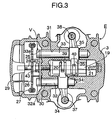
- an engine body E of an SOHC-type air-cooled 4-cycle internal combustion engine includes a cylinder block 1 having a cylinder bore 2 provided therein, a cylinder head 3 which is fixed to a deck surface of the cylinder block 1 and has a combustion chamber 4 defined therein to confront the cylinder bore 2, and a crankcase 5 fixed to a lower surface of the cylinder block 1.
- a valve-operating device V which will be described hereinafter, is mounted in the cylinder head 3, and a head cover 6 is mounted on the cylinder head 3 to cover the valve-operating device V.
- a piston 8 is slidably received in the cylinder bore 2 with a cylinder sleeve 7 interposed therebetween, and is connected to a crankshaft which is not shown through a connecting rod 10.
- This internal combustion engine is of a uni-flow type, and the cylinder 3 is provided with an intake port 11 which opens into one side of the cylinder head 3, and an exhaust port 12 which opens into the other side of the cylinder head.
- the intake port 11 and the exhaust port 12 are opposed to each other.
- An intake system In is connected to the intake port 11, and an exhaust system Ex is connected to the exhaust port 12.
- An intake valve 13 is mounted in the intake port 11 for opening and closing an intake valve bore permitting the intake port 11 and the combustion chamber 4 into communication with each other
- an exhaust valve 14 is mounted in the exhaust port 12 for opening and closing an exhaust valve bore permitting the exhaust port 12 and the combustion chamber 4 into communication with each other.
- the intake and exhaust valves 13 and 14 are retained as usual in their closed positions by valve springs 15 and 16, respectively.
- a spark plug 17 is threadedly mounted in a wall surface of the cylinder head 3 surrounding the combustion chamber 4 with its electrode facing into the combustion chamber 4.
- a single valve-operating camshaft 19 is rotatably carried in a central portion of a valve-operating chamber defined above the cylinder head 3 with bearings 23 and 24 interposed therebetween.
- An intake cam 20 and an exhaust cam 21 are integrally formed at an axially intermediate portion of the valve-operating camshaft 19.
- a timing transmitting chamber 25 is defined in one side (a left side in Figs. 2 and 3) of and astride the cylinder block 1 and the cylinder head 3, and a timing driven gear 26 is fixed at one end (a left end in Figs.2 and 3) of the valve-operating camshaft 19 within the timing transmitting chamber 25.
- the gear 26 is operated in operative association with a timing driving gear fixed on a crankshaft (not shown) through an endless timing chain 27, so that the rotation of the crankshaft is transmitted at a reduction ratio of 1/2 to the valve-operating camshaft as usual.
- a bolt 28 passed through a sidewall of the cylinder head 3 is inserted through the hollow valve-operating camshaft 19, and a cover 29 is threadedly mounted to an end of the bolt 28 to cover an opening in the timing transmitting chamber 25 on the side of the cylinder head 3.
- Intake-side and exhaust-side two rocker arm shaft bores 30 and 31 are provided in the cylinder head 3 to extend laterally above the valve-operating camshaft 19 in parallel to the valve-operating camshaft 19.
- the intake-side and exhaust-side two rocker arm shaft bores 30 and 31 are formed as blind bores which open into the timing transmitting chamber 25, as shown in Fig.3.
- the exhaust-side rocker arm shaft bore 31 is formed longer than the intake-side rocker arm shaft bore 30.
- Two, i.e., intake-side and exhaust-side hollow rocker arm shafts 32 and 33 are press-fitted into the two rocker arm shaft bores 30 and 31 from the sides of their openings.
- Intake-side and exhaust-side rocker arms 34 and 35 are swingably supported at their intermediate portions on the two rocker arm shafts 32 and 33 with their positions displaced from each other in axial directions of the rocker arm shafts 32 and 33, respectively.
- the intake-side rocker arm 34 is connected at its outer end to an upper end of the intake valve 13 through a tappet 37 and at its inner end to a cam face of the intake cam 20 on the valve-operating camshaft 19 through a roller 39 pivotably supported at such inner end.
- the exhaust-side rocker arm 35 is connected at its outer end to an upper end of the exhaust valve 14 through a tappet 38 and at its inner end to a cam face of the exhaust cam 21 on the valve-operating camshaft 19 through a roller 40 pivotably supported at such inner end. Therefore, the rotation of the valve-operating camshaft 19 causes the intake-side and exhaust-side rocker arms 34 and 35 to be swung about the rocker arm shafts 32 and 33, respectively, whereby the intake valve 13 and the exhaust valve 14 are opened and closed with a predetermined timing by cooperation with the valve springs 15 and 16 to conduct the operation of the internal combustion engine.
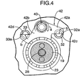
- the two intake-side and exhaust-side rocker arm shafts 32 and 33 are provided with detent means, so that the rocker arm shafts 32 and 33 are prevented from being freely rotated within the rocker arm shaft bores 30 and 31, even if the valve-operating device V is operated. More specifically, as shown in Figs. 3 and 4, a detent plate 42 is fixed at its central portion in a tightened manner by a threaded member, namely, a tightening bolt 43 immediately above and in parallel to the valve-operating camshaft 19.
- the detent plate 42 is integrally formed with a first arm 42a extending toward the intake-side rocker arm shaft 32, and a second arm 42b extending toward the exhaust-side rocker arm shaft 33, and has a lower surface formed as an arcuate recessed surface substantially concentric with the valve-operating camshaft 19.
- Flat engage portions 42c and 42d capable of being engaged with engaged portions 32a and 33a (which will be described hereinafter) of the two rocker arm shafts 32 and 33 are formed on the first and second arms 42a and 42b of the detent plate 42 at side faces of ends of the detent plate 42 on a front side in a direction of tightening rotation of the tightening bolt 43. As shown in Fig.
- the engage portion 42c of the first arm 42a is formed in a downward turned attitude on the side face of the end, while the engage portion 42d of the second arm 42b is formed in an upward turned attitude on the side face of the end.
- the engaged portions 32a and 33a notched in a semi-circular shape are formed at one ends of the two rocker arm shafts 32 and 33 corresponding to the detent plate 42.
- the tightening bolt 43 is rotated in the tightening direction (a direction indicated by an arrow a in Fig.4) to fix the detent plate 42 in the tightened manner to the cylinder head 3 by the tightening bolt 43, the detent plate 42 is also rotated in the same direction (a direction indicated by an arrow b in Fig.
- the detent device for the rocker arm shafts according to the present invention has been described as being carried out in the SOHC-type internal combustion engine in the above-described embodiment, but it is of course that the detent device is applicable to another internal combustion engine including two rocker arm shafts.
Landscapes
- Engineering & Computer Science (AREA)
- Mechanical Engineering (AREA)
- General Engineering & Computer Science (AREA)
- Valve-Gear Or Valve Arrangements (AREA)
Applications Claiming Priority (3)
| Application Number | Priority Date | Filing Date | Title |
|---|---|---|---|
| JP2001279703A JP3526836B2 (ja) | 2001-09-14 | 2001-09-14 | 内燃機関の動弁装置におけるロッカアームシャフトの回り止め装置 |
| JP2001279703 | 2001-09-14 | ||
| PCT/JP2002/008678 WO2003027447A1 (fr) | 2001-09-14 | 2002-08-28 | Dispositif a butee tourbillon pour axe de culbuteur d'un mecanisme de soupapes de moteur a combustion interne |
Publications (3)
| Publication Number | Publication Date |
|---|---|
| EP1452699A1 true EP1452699A1 (fr) | 2004-09-01 |
| EP1452699A4 EP1452699A4 (fr) | 2007-05-02 |
| EP1452699B1 EP1452699B1 (fr) | 2009-07-22 |
Family
ID=19103835
Family Applications (1)
| Application Number | Title | Priority Date | Filing Date |
|---|---|---|---|
| EP02762894A Expired - Fee Related EP1452699B1 (fr) | 2001-09-14 | 2002-08-28 | Dispositif a butee tourbillon pour axe de culbuteur d'un mecanisme de soupapes de moteur a combustion interne |
Country Status (8)
| Country | Link |
|---|---|
| EP (1) | EP1452699B1 (fr) |
| JP (1) | JP3526836B2 (fr) |
| KR (1) | KR100567568B1 (fr) |
| CN (1) | CN100580227C (fr) |
| AR (1) | AR036522A1 (fr) |
| BR (1) | BR0205989B1 (fr) |
| MY (1) | MY129621A (fr) |
| WO (1) | WO2003027447A1 (fr) |
Cited By (1)
| Publication number | Priority date | Publication date | Assignee | Title |
|---|---|---|---|---|
| EP1895112A1 (fr) * | 2005-06-23 | 2008-03-05 | HONDA MOTOR CO., Ltd. | Jeu de soupapes d' un moteur |
Families Citing this family (4)
| Publication number | Priority date | Publication date | Assignee | Title |
|---|---|---|---|---|
| JP4052964B2 (ja) * | 2003-03-19 | 2008-02-27 | 本田技研工業株式会社 | ロッカーアーム軸の回り止め装置 |
| JP4566071B2 (ja) * | 2005-06-15 | 2010-10-20 | 本田技研工業株式会社 | 内燃機関 |
| JP4629003B2 (ja) * | 2006-07-11 | 2011-02-09 | 本田技研工業株式会社 | 内燃機関の動弁装置 |
| JP6898377B2 (ja) * | 2019-03-29 | 2021-07-07 | 本田技研工業株式会社 | 内燃機関の動弁構造 |
Family Cites Families (3)
| Publication number | Priority date | Publication date | Assignee | Title |
|---|---|---|---|---|
| JPS5531201Y2 (fr) * | 1976-03-16 | 1980-07-25 | ||
| JP3518698B2 (ja) * | 1994-10-11 | 2004-04-12 | 本田技研工業株式会社 | 動弁装置のカムシャフトと開弁用スイングアームシャフトの軸方向固定構造 |
| JP3369036B2 (ja) * | 1995-12-26 | 2003-01-20 | ヤマハ発動機株式会社 | 頭上カム式エンジン |
-
2001
- 2001-09-14 JP JP2001279703A patent/JP3526836B2/ja not_active Expired - Fee Related
-
2002
- 2002-08-28 BR BRPI0205989-4A patent/BR0205989B1/pt not_active IP Right Cessation
- 2002-08-28 CN CN02817041A patent/CN100580227C/zh not_active Expired - Fee Related
- 2002-08-28 EP EP02762894A patent/EP1452699B1/fr not_active Expired - Fee Related
- 2002-08-28 WO PCT/JP2002/008678 patent/WO2003027447A1/fr active Application Filing
- 2002-08-28 KR KR1020047002824A patent/KR100567568B1/ko not_active IP Right Cessation
- 2002-09-13 AR ARP020103475A patent/AR036522A1/es active IP Right Grant
- 2002-09-14 MY MYPI20023433A patent/MY129621A/en unknown
Non-Patent Citations (2)
| Title |
|---|
| No further relevant documents disclosed * |
| See also references of WO03027447A1 * |
Cited By (2)
| Publication number | Priority date | Publication date | Assignee | Title |
|---|---|---|---|---|
| EP1895112A1 (fr) * | 2005-06-23 | 2008-03-05 | HONDA MOTOR CO., Ltd. | Jeu de soupapes d' un moteur |
| EP1895112A4 (fr) * | 2005-06-23 | 2011-02-23 | Honda Motor Co Ltd | Jeu de soupapes d' un moteur |
Also Published As
| Publication number | Publication date |
|---|---|
| EP1452699A4 (fr) | 2007-05-02 |
| WO2003027447A1 (fr) | 2003-04-03 |
| KR100567568B1 (ko) | 2006-04-05 |
| JP2003083009A (ja) | 2003-03-19 |
| MY129621A (en) | 2007-04-30 |
| AR036522A1 (es) | 2004-09-15 |
| JP3526836B2 (ja) | 2004-05-17 |
| EP1452699B1 (fr) | 2009-07-22 |
| CN1549888A (zh) | 2004-11-24 |
| CN100580227C (zh) | 2010-01-13 |
| BR0205989A (pt) | 2003-08-26 |
| KR20040029441A (ko) | 2004-04-06 |
| BR0205989B1 (pt) | 2011-03-09 |
Similar Documents
| Publication | Publication Date | Title |
|---|---|---|
| EP0601250B1 (fr) | Dispositif de commande de soupapes pour moteur à combustion interne | |
| JP5378091B2 (ja) | 内燃機関の動弁系回転軸の固定構造 | |
| EP1683944B1 (fr) | Mecanisme de commande de soupape comprenant un culbuteur de soupape a galet, moteur a quatre temps et motocycle equipe d'un moteur a quatre temps | |
| JP5149268B2 (ja) | 回転角センサ取り付け構造及び同構造を用いた内燃機関の可変動弁装置 | |
| US4796574A (en) | SOHC type internal combustion engine | |
| JP4014185B2 (ja) | エンジンのプッシュロッドカバー構造 | |
| EP1452699B1 (fr) | Dispositif a butee tourbillon pour axe de culbuteur d'un mecanisme de soupapes de moteur a combustion interne | |
| US5398649A (en) | S.O.H.C. five valve engine | |
| US6953015B2 (en) | Engine | |
| EP1403497B1 (fr) | Structure des paliers pour des arbres aux cames d' un moteur à combustion interne avec double arbres aux cames en la culasse | |
| US20080029052A1 (en) | Mounting structure of ignition plug tube | |
| KR101013253B1 (ko) | 로커 아암축의 회전 방지 장치 | |
| EP1344930A2 (fr) | Moteur à combustion interne avec soupape d'injection de carburant | |
| JP3272245B2 (ja) | 4サイクルエンジンのチェーンカバー構造 | |
| JP3327322B2 (ja) | バルブタイミング可変装置を備えた4サイクルエンジン | |
| JPS5677519A (en) | Cylinder head for overhead camshaft type four-cycle engine | |
| JP3358960B2 (ja) | Sohc型内燃機関 | |
| US5685265A (en) | Multi valve engine | |
| US5024187A (en) | System for axially locating a camshaft | |
| EP1207274B1 (fr) | Distribution pour moteur 4 cylindres à soupapes en tête | |
| JPH03222804A (ja) | 内燃機関のロッカアームシャフト取付構造 | |
| JP2000130112A (ja) | 車両用エンジン | |
| JP2700376B2 (ja) | Ohcエンジンの動弁機構 | |
| JPH06288205A (ja) | 動弁装置 | |
| US20160222834A1 (en) | Valve lifter assembly of engine |
Legal Events
| Date | Code | Title | Description |
|---|---|---|---|
| PUAI | Public reference made under article 153(3) epc to a published international application that has entered the european phase |
Free format text: ORIGINAL CODE: 0009012 |
|
| 17P | Request for examination filed |
Effective date: 20040202 |
|
| AK | Designated contracting states |
Kind code of ref document: A1 Designated state(s): AT BE BG CH CY CZ DE DK EE ES FI FR GB GR IE IT LI LU MC NL PT SE SK TR |
|
| AX | Request for extension of the european patent |
Extension state: AL LT LV MK RO SI |
|
| A4 | Supplementary search report drawn up and despatched |
Effective date: 20070330 |
|
| REG | Reference to a national code |
Ref country code: DE Ref legal event code: 8566 |
|
| GRAP | Despatch of communication of intention to grant a patent |
Free format text: ORIGINAL CODE: EPIDOSNIGR1 |
|
| GRAS | Grant fee paid |
Free format text: ORIGINAL CODE: EPIDOSNIGR3 |
|
| GRAA | (expected) grant |
Free format text: ORIGINAL CODE: 0009210 |
|
| AK | Designated contracting states |
Kind code of ref document: B1 Designated state(s): FR GB GR TR |
|
| REG | Reference to a national code |
Ref country code: GB Ref legal event code: FG4D |
|
| REG | Reference to a national code |
Ref country code: GR Ref legal event code: EP Ref document number: 20090402364 Country of ref document: GR |
|
| PLBE | No opposition filed within time limit |
Free format text: ORIGINAL CODE: 0009261 |
|
| STAA | Information on the status of an ep patent application or granted ep patent |
Free format text: STATUS: NO OPPOSITION FILED WITHIN TIME LIMIT |
|
| 26N | No opposition filed |
Effective date: 20100423 |
|
| REG | Reference to a national code |
Ref country code: GB Ref legal event code: 746 Effective date: 20120521 |
|
| PGFP | Annual fee paid to national office [announced via postgrant information from national office to epo] |
Ref country code: GR Payment date: 20120726 Year of fee payment: 11 |
|
| PGFP | Annual fee paid to national office [announced via postgrant information from national office to epo] |
Ref country code: FR Payment date: 20120823 Year of fee payment: 11 |
|
| PGFP | Annual fee paid to national office [announced via postgrant information from national office to epo] |
Ref country code: GB Payment date: 20130828 Year of fee payment: 12 Ref country code: TR Payment date: 20130719 Year of fee payment: 12 |
|
| REG | Reference to a national code |
Ref country code: GR Ref legal event code: ML Ref document number: 20090402364 Country of ref document: GR Effective date: 20140305 |
|
| REG | Reference to a national code |
Ref country code: FR Ref legal event code: ST Effective date: 20140430 |
|
| PG25 | Lapsed in a contracting state [announced via postgrant information from national office to epo] |
Ref country code: GR Free format text: LAPSE BECAUSE OF NON-PAYMENT OF DUE FEES Effective date: 20140305 |
|
| PG25 | Lapsed in a contracting state [announced via postgrant information from national office to epo] |
Ref country code: FR Free format text: LAPSE BECAUSE OF NON-PAYMENT OF DUE FEES Effective date: 20130902 |
|
| GBPC | Gb: european patent ceased through non-payment of renewal fee |
Effective date: 20140828 |
|
| PG25 | Lapsed in a contracting state [announced via postgrant information from national office to epo] |
Ref country code: GB Free format text: LAPSE BECAUSE OF NON-PAYMENT OF DUE FEES Effective date: 20140828 |
|
| PG25 | Lapsed in a contracting state [announced via postgrant information from national office to epo] |
Ref country code: TR Free format text: LAPSE BECAUSE OF NON-PAYMENT OF DUE FEES Effective date: 20140828 |