EP1452392B1 - Verfahren zur Herstellung eines abblendbaren Kraftfahrzeugsrückspiegel - Google Patents
Verfahren zur Herstellung eines abblendbaren Kraftfahrzeugsrückspiegel Download PDFInfo
- Publication number
- EP1452392B1 EP1452392B1 EP04013529A EP04013529A EP1452392B1 EP 1452392 B1 EP1452392 B1 EP 1452392B1 EP 04013529 A EP04013529 A EP 04013529A EP 04013529 A EP04013529 A EP 04013529A EP 1452392 B1 EP1452392 B1 EP 1452392B1
- Authority
- EP
- European Patent Office
- Prior art keywords
- bracket
- control lever
- mirror
- runner
- mirror housing
- Prior art date
- Legal status (The legal status is an assumption and is not a legal conclusion. Google has not performed a legal analysis and makes no representation as to the accuracy of the status listed.)
- Expired - Lifetime
Links
- 238000000034 method Methods 0.000 title claims description 16
- 238000004519 manufacturing process Methods 0.000 title claims description 11
- 238000000465 moulding Methods 0.000 claims description 4
- 238000000926 separation method Methods 0.000 claims description 4
- 230000000052 comparative effect Effects 0.000 description 9
- 230000008569 process Effects 0.000 description 6
- 241000276425 Xiphophorus maculatus Species 0.000 description 5
- 238000002310 reflectometry Methods 0.000 description 4
- 230000008859 change Effects 0.000 description 3
- 230000007547 defect Effects 0.000 description 2
- 238000002347 injection Methods 0.000 description 2
- 239000007924 injection Substances 0.000 description 2
- 230000007246 mechanism Effects 0.000 description 2
- 230000007306 turnover Effects 0.000 description 2
- 230000009471 action Effects 0.000 description 1
- 230000002950 deficient Effects 0.000 description 1
- 230000000007 visual effect Effects 0.000 description 1
Images



Classifications
-
- B—PERFORMING OPERATIONS; TRANSPORTING
- B60—VEHICLES IN GENERAL
- B60R—VEHICLES, VEHICLE FITTINGS, OR VEHICLE PARTS, NOT OTHERWISE PROVIDED FOR
- B60R1/00—Optical viewing arrangements; Real-time viewing arrangements for drivers or passengers using optical image capturing systems, e.g. cameras or video systems specially adapted for use in or on vehicles
-
- B—PERFORMING OPERATIONS; TRANSPORTING
- B60—VEHICLES IN GENERAL
- B60R—VEHICLES, VEHICLE FITTINGS, OR VEHICLE PARTS, NOT OTHERWISE PROVIDED FOR
- B60R1/00—Optical viewing arrangements; Real-time viewing arrangements for drivers or passengers using optical image capturing systems, e.g. cameras or video systems specially adapted for use in or on vehicles
- B60R1/02—Rear-view mirror arrangements
- B60R1/08—Rear-view mirror arrangements involving special optical features, e.g. avoiding blind spots, e.g. convex mirrors; Side-by-side associations of rear-view and other mirrors
- B60R1/083—Anti-glare mirrors, e.g. "day-night" mirrors
- B60R1/086—Anti-glare mirrors, e.g. "day-night" mirrors using a mirror angularly movable between a position of use and a non-glare position reflecting a dark field to the user, e.g. situated behind a transparent glass used as low-reflecting surface; Wedge-shaped mirrors
-
- B—PERFORMING OPERATIONS; TRANSPORTING
- B29—WORKING OF PLASTICS; WORKING OF SUBSTANCES IN A PLASTIC STATE IN GENERAL
- B29C—SHAPING OR JOINING OF PLASTICS; SHAPING OF MATERIAL IN A PLASTIC STATE, NOT OTHERWISE PROVIDED FOR; AFTER-TREATMENT OF THE SHAPED PRODUCTS, e.g. REPAIRING
- B29C45/00—Injection moulding, i.e. forcing the required volume of moulding material through a nozzle into a closed mould; Apparatus therefor
- B29C45/0053—Injection moulding, i.e. forcing the required volume of moulding material through a nozzle into a closed mould; Apparatus therefor combined with a final operation, e.g. shaping
- B29C45/006—Joining parts moulded in separate cavities
-
- B—PERFORMING OPERATIONS; TRANSPORTING
- B29—WORKING OF PLASTICS; WORKING OF SUBSTANCES IN A PLASTIC STATE IN GENERAL
- B29C—SHAPING OR JOINING OF PLASTICS; SHAPING OF MATERIAL IN A PLASTIC STATE, NOT OTHERWISE PROVIDED FOR; AFTER-TREATMENT OF THE SHAPED PRODUCTS, e.g. REPAIRING
- B29C45/00—Injection moulding, i.e. forcing the required volume of moulding material through a nozzle into a closed mould; Apparatus therefor
- B29C45/0053—Injection moulding, i.e. forcing the required volume of moulding material through a nozzle into a closed mould; Apparatus therefor combined with a final operation, e.g. shaping
- B29C45/006—Joining parts moulded in separate cavities
- B29C2045/0065—Joining parts moulded in separate cavities the parts being interconnected before assembling by a breaking or shearing point
Definitions
- the present invention relates to a method for manufacturing an anti-glare rearview mirror for vehicles, and more particularly, to a method for enabling an efficient assembling of an anti-glare rearview mirror for vehicles.
- An automobile is generally equipped with an anti-glare rearview mirror in the driver's compartment so that good visibility of the driver is ensured by adjusting its reflectivity even if the driver is dazzled by the light of the following car.
- Most of the anti-glare rearview mirrors have a prismatic mirror whose front face and rear face are different in reflectivity, and the rearview mirror is movable between normal position and anti-glare position by turning the prismatic mirror at a certain angle while providing the driver with the same visual field.
- An anti-glare rearview mirror consists of a mirror, a mirror housing, a rectangular bracket, a control lever, and a fixing stay.
- the bracket has a turning axle that is projecting outwardly from both ends of one side, and on the opposite side of its turning axle, the bracket has an engaging portion.
- This bracket is pivotally mounted to the mirror housing to which the prismatic mirror is fixed.
- the control lever for controlling movement of the mirror between normal and anti-glare position, consists of a stick-shaped body and a flat handle provided along and at the mid-point of the body. Also, an engaging portion is formed on one side of the stick-shaped body.
- This control lever is also pivotally mounted to the mirror housing with its engaging portion meshed with the engaging portion of the bracket.
- This rearview mirror is fixed to the vehicle body by a fixing stay that connects the bracket with the vehicle body through an aperture of the mirror housing.
- the bracket and the control lever of this anti-glare mirror are molded together in one die for reducing the cost of the die as well as saving the time for molding. Therefore, as illustrated in Fig. 4 or Fig. 5, the bracket and the control lever are molded integrally and connected by runners.
- a bracket 101 and a control lever 102 respectively have an engaging portion 101a, 102a which are to be engaged each other.
- the bracket 101 and the control lever 102 are molded together in such a manner that a sub runner 106 vertically branched from a main runner 105 connects the engaging portions 101a, 102a with said engaging portions 101a, 102a faced each other.
- the assembler cuts off the sub runner 106, brings the bracket 101 and the lever 102 close to each other while retaining the facing posture, engages the engaging portions 101a, 102a, and places the assembly into a mirror housing (Fig. 4B).
- a bracket 111 and a control lever 112 respectively have an engaging portion 111a, 112a which are to be engaged each other.
- the bracket 111 and the control lever 112 are molded together in such a manner that two U-shaped runners 116 connect both ends of a turning pivot 118 of the control lever 112 and the side parts 117 of the bracket 111, with said engaging portions 111a, 112a faced each other.
- the a forementioned conventional anti-glare mirror shown in Fig. 4A has a drawback if the bracket 101 and the control lever 102 are separated at the runner 106 and assembled together into the anti-glare mirror without removing remaining parts or burrs of the runner 106.
- the drawback is that the remaining parts interfere each other upon operating the control lever 102, as illustrated in Fig. 4B, resulting defective operation of the control lever 102 or rapping sounds during the operation. Therefore, it is necessary to remove the remaining parts of the runner 106 from the bracket 101 and the control lever 102 respectively with use of nippers and the like.
- the aforementioned conventional anti-glare mirror has a similar drawback in that if the bracket 111 and the control lever 112 are separated at the runners 116 and assembled together without removing remaining parts or burrs of the runners 116, as illustrated in Fig. 5B, the remaining parts interfere each other.
- US-A-5 327 288 describes a rearview mirror assembly and a method of manufacturing such an assembly corresponding to the preamble of claims 3 and 1 respectively.
- EP-A-382 345 describes on electrical corrector forming integrally moulded with a key.
- a first aspect of the present invention provides a method for manufacturing an anti-glare rearview mirror according to claim 1.
- the present invention also provides an integrally moulded bracket and control lever for use in manufacturing an antiglare rear-view mirror according to claim 3.
- Shifting the control lever relative to the bracket in the direction of its turning axis in this manner prevents an interference of these parts with the runner, so that a worker can leave out removing process of the runners.
- the runner may have a weak section for facilitating a handwork separation of said control lever from said bracket.
- This weak section allows a worker to assemble the bracket and the control lever into a mirror housing through an operation of holding the integrally-molded bracket and lever in each hand and of separating them with a twisting action and the like, while the worker needs no turning operation of these parts. In this way, the assembly process of anti-glare rearview mirror for vehicles becomes more efficient.
- Fig. 1 illustrates a perspective view of an anti-glare rearview mirror after a bracket and a control lever has assembled to a mirror housing
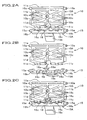
- Fig. 2A illustrates a perspective view of the bracket and the control lever molded integrally according to a comparative embodiment
- Fig. 2B illustrates a perspective view of the bracket and the control lever separated from each other according to the comparative embodiment
- Fig. 2C illustrates a perspective view of the bracket and the control lever assembled to the mirror housing according to the comparative embodiment.
- an anti-glare rearview mirror for vehicles with respect to the first embodiment of a method for manufacturing the mirror comprises a mirror 4 , a mirror housing 5, a rectangular platy bracket 10, and a control lever 15 for controlling the movement of the rearview mirror between a normal position and an anti-glare position.
- the bracket 10 is pivotally mounted to the mirror housing 5 to turn around a bracket-turning pivot 10a.
- This bracket 10 is fixed to a vehicle body by a fixing stay 6.
- the control lever 15 is rotatably mounted on the mirror housing 5 thereby enabling the control lever 15 to turn around a lever-turning pivot 15a.
- a side of the bracket 10 is meshed with a side of the control lever 15, so a turning operation of the control lever 15 turns the bracket 10 and varies the relative angle between the mirror housing 5 and the bracket 10.
- the mirror 4 is a prismatic mirror having different reflectivity between its front and rear face, the reflectivity of the rearview mirror changes in accordance with the change in the above relative angle.
- the bracket 10 and the control lever 15 are molded together in one die by one-shot injection and are connected by a runner 18 for reducing the cost of the die as well as saving time for molding.
- the bracket 10 comprises a rectangular platy bracket body 10A and the bracket-turning pivot 10a projecting outwardly from both ends of upper side 11a in Fig. 2A.
- the bracket-turning pivot 10a is pivotally mounted to a support hole 5a of the mirror housing 5 as shown in Fig. 1, so the bracket 10 is rotatable relative to the mirror housing 5 as a result.
- the bracket 10 is formed an engaging portion 11c that meshes with the control lever 15 by uneven faces and that is arranged on a lower side away from and opposite to the upper side 11a.
- the engaging portion 11c is divided right and left in two by forming a rectangular recess 11d at the mid-point of the lower side.
- the bracket body 10A also has a spherical recess 10b at the center thereof, and a spherical part, which fits to the spherical recess 10b, is formed at the end of the fixing stay 6 while the fixing stay 6 is fixed to the vehicle body. Fitting the spherical part to the spherical recess 10b allows the mirror housing 5 to turn over freely while the mirror housing 5 is fit to the vehicle body.
- the bracket body 10A also comprises ribs 10c... all around the edge of the bracket's face and between its four corners and the spherical recess 10b in order to reinforce itself.
- the control lever 15 comprises the lever-turning pivots 15a projecting from the both ends of and along a lever body 15A having polygonal section and stick shape.
- the lever-turning pivot 15a is pivotally mounted to the support hole 5b of the mirror housing 5, so the control lever 15 is rotatable relative to the mirror housing 5 as a result.
- the control lever 15 also comprises an engaging portion 16c on the upper side of the lever body 15A in Fig. 2A.
- the engaging portion 16c meshes with the engaging portion 11c of the bracket 10 in order to transmit the motion of the control lever 15 to the bracket 10, and thereby enables the bracket 10 to turn around the bracket-turning pivot 10a.
- the engaging portion 16c is divided right and left in two by forming a projected T-shaped runner 18 at the mid-point of the engaging portion 16c.
- the lever body 15A also comprises a rectangular platy handle 15b at the mid-point of the opposite side and along the lever body 15A.
- bracket 10 and control lever 15 are molded integrally connected by the runner 18 with the engaging portion 11c and the engaging portion 16c faced each other.
- the runner 18 extends from the mid-point of the engaging portion 16c toward the recess 11d, branches right and left inside the recess 11d, and connects to the bracket 10 to form T-shape.
- the branched parts are partly narrow to make a weak section 18a that is weaker than general section of the branch.
- This weak section 18a enables an easy handwork separation of the control lever 15 from the bracket 10 by twisting the control lever 15 against the bracket 10.
- the depth and width of the recess 11d is respectively deeper and wider than the length and width of the runner 18 toward the recess 11d, thus there is no interference between the runner 18 and the recess 11d when they are assembled into a rearview mirror.
- a rearview mirror is manufactured by using the bracket 10 and the control lever 15 as mentioned above through following processes.
- the bracket 10 and the control lever 15 are molded integrally connected with the runner 18.
- an assembler holds the bracket 10 and the control lever 15 in each hand and twists them to tear at the weak section 18a, then, as shown in Fig. 2B, the bracket 10 and the control lever 15 are separated as a result.
- the assembler keeps holding the bracket 10 and the control lever 15 and brings them close to each other. Then, as shown in Fig. 2C, the remained runner 18 is shifted front and back and the engaging portion 11c is meshed with the engaging portion 16c. Holding these parts meshed, the assembler fits the bracket-turning pivot 10a in the support hole 5a of the mirror housing 5, and he pushes the lever-turning pivot 15a into the support hole 5b to fit in. Then he fits the fixing stay 6 in the spherical recess 10b of the bracket 10 and, further, he fits the mirror 4 to the front edge of the mirror housing to finish assembling the rearview mirror.
- an assembler can fit the bracket 10 and the control lever 15 in the mirror housing 5 only by twisting and tearing the runner 18 without removing the remaining runner 18 or without changing his holding positions. Moreover, because the bracket 10 has a recess 11d to be away from movable area of the runner 18 at their assembled arrangement, the runner 18 does not interfere with the bracket 10 or recess 11d without removing the remaining runner 18. As a result, there is no defect of producing so-called rapping sound.
- an assembler can abbreviate a process of cutting off a runner, and can assemble an anti-glare rearview mirror more efficiently. Further, not only manpower required for cutting off the runners 18 but also space for storing brackets 10 and control levers 15 separately become unnecessary.
- FIG. 3A illustrates a plan view of a bracket and a control lever molded integrally according to the embodiment of the invention
- Fig. 3B illustrates a plan view of the bracket and the control lever engaged with each other according to the embodiment of the present invention.
- parts or elements similar to those previously described regarding the comparative embodiment will be denoted by the same reference numbers and the description thereof will be omitted.
- a bracket 30 and a control lever 35 are molded together in one die by one-shot injection and are connected by a runner 38 for reducing the cost of the die as well as saving time for molding.
- the bracket 30 comprises a rectangular platy bracket body 30A and the bracket-turning pivot 30a projecting outwardly from both ends of upper side 31a in Fig. 3A.
- the bracket-turning pivot 30a is pivotally mounted to a support hole 5a of the mirror housing 5 as shown in Fig. 1, so the bracket 30 is rotatable relative to the mirror housing 5 as a result.
- the lower side of the bracket 30 opposite to and away from the upper side31a is provided with an uneven-faced engaging portion 21c extending half the length of the lower side at its mid-point, and meshable with the control lever 25.
- the engaging portion 31c is divided right and left in two at its mid-point by forming a rectangular recess 31b.
- the bracket body 30A also has a spherical recess 30b at the center thereof, and a spherical part, which fits to the spherical recess 30b, is formed at the end of the fixing stay 6 while the fixing stay 6 (not shown) is fixed to the vehicle body. Fitting the spherical part to the spherical recess 30b allows the mirror housing 5 to turn over freely while the mirror housing is fit to the vehicle body.
- the bracket body 30A also comprises ribs 30c... all around the edge of the bracket's face and between its four corners and the spherical recess 30b in order to reinforce itself.
- the control lever 35 comprises the lever-turning pivots 35a projecting from the both end faces 36b and along a lever body 35A having polygonal section and stick shape.
- the lever-turning pivot 35a is pivotally mounted to the support hole 5b of the mirror housing 5, so the control lever 35 is rotatable relative to the mirror housing 5 as a result.
- the lower side of the lever body 35A is provided with an engaging portion 36c that will mesh with an engaging portion 31c along the half middle of the lower side.
- the engaging portion 36c is divided right and left in two by forming a rectangular recess 36d at its mid-point.
- the engaging portion 36c meshes with the engaging portion 31c of the bracket 30 in order to transmit the motion of the control lever 35 to the bracket 30, and thereby enables the bracket 30 to turn around the bracket-turning pivot 30a.
- the lever body 35A also comprises a trapeziform platy handle 35b at the mid-point of the opposite side and along the lever body 35A.
- the bracket 30 and the control lever 35 are connected with each other by a runner 38 with their engaging portions faced each other and shifted relative to their meshing position.
- the runner 38 has thin cylindrical shape and comprises a weak section 38a having narrower section at its center than other section of the runner 38. Further, the above recess 31d and the recess 36d notched deeply enough not to interfere the movement of remained runner 38 after they are separated and assembled.
- a rearview mirror is manufactured by using the bracket 30 and the control lever 35 as mentioned above through following processes. As shown in Fig. 3A, the bracket 30 and the control lever 35 are molded integrally connected with the runner 38. And an assembler holds the bracket 30 and the control lever 35 in each hand and draw, bend, or twists them to tear at the weak section 38a, then, the bracket 30 and the control lever 35 are separated as a result.
- the assembler keeps holding the bracket 30 and the control lever 35 and brings them close to each other. Then, as shown in Fig. 3B, the remained runner 18 is shifted front and back and the engaging portion 31c is meshed with the engaging portion 36c. Holding these parts meshed, the assembler fits the bracket-turning pivot 30a in the support hole 5a of the mirror housing 5, and he pushes the lever-turning pivot 35a into the support hole 5b to fit in. Then he fits the fixing stay 6 in the spherical recess 30b of the bracket 10 and, further, he fits the mirror 4 to the front of the mirror housing to finish assemble of the rearview mirror.
- an assembler can fit the bracket 30 and the control lever 35 in the mirror housing 5 only by tearing the runner 38 by twisting or the like them with his hands without removing the remaining runner 38 or without changing his holding positions. Moreover, because the recess 31d and the recess 36d is notched deep enough not to interfere the motion of the remained runners 38 after they are separated and assembled, there is no defect of producing so-called rapping sound. According to the present embodiment, therefore, an assembler can abbreviate a process of cutting off a runner, and can assemble an anti-glare rearview mirror more efficiently. Further, not only manpower required for cutting off the runners 38 but also space for storing brackets 30 and control levers 35 separately become unnecessary.
- a runner for connecting a bracket and a control lever may be formed in such a manner that the runner does not interfere a motion of assembled bracket or control lever by a turning operation of the control lever.
- the runner may be provided at various places, for example, at a corner of a bracket, at an end of a turning pivot, or at a side of an engaging portion formed protruding shape.
Landscapes
- Engineering & Computer Science (AREA)
- Mechanical Engineering (AREA)
- Multimedia (AREA)
- Manufacturing & Machinery (AREA)
- Rear-View Mirror Devices That Are Mounted On The Exterior Of The Vehicle (AREA)
- Mounting And Adjusting Of Optical Elements (AREA)
Claims (4)
- Verfahren zur Herstellung eines blendfreien Rückspiegels, wobei der zusammengesetzte Rückspiegel einen Spiegel (4), ein Spiegelgehäuse (5) zum Halten des Spiegels, eine Auflage (30), die schwenkbar am Spiegelgehäuse angebracht ist, und einen Stellhebel (35) umfasst, der schwenkbar am Spiegelgehäuse angebracht und mit der Auflage in Eingriff ist, sodass ein relativer Winkel zwischen der Auflage und dem Spiegelgehäuse verändert werden kann, indem der Stellhebel relativ zum Spiegelgehäuse drehbetätigt wird;
wobei das Verfahren durch die folgenden Schritte gekennzeichnet ist:worin:Formen der Auflage und des Stellhebels auf eine Weise, sodass ein Anguss (38) die Auflage und den Stellhebel einstückig miteinander verbindet;Trennen der Auflage und des Stellhebels am Anguss; undZusammensetzen der Auflage und des Stellhebels im Spiegelgehäuse ohne Entfernen eines Restteils des Angusses;die Auflage und der Stellhebel so geformt sind, dass Eingreifabschnitte (31 c, 36c) der Auflage und des Stellhebels einander gegenüberliegen und bezüglich ihrer Eingreifposition verschoben sind, sodass die Restteile des Angusses zueinander versetzt sind, wenn die Auflage und der Stellhebel im Spiegelgehäuse zusammengesetzt sind, sodass die Restteile des Angusses die Bewegung der Auflage oder des Stellhebels im zusammengesetzten Rückspiegel nicht beeinträchtigen. - Verfahren nach Anspruch 1, worin der Anguss eine Schwachstelle (38a) aufweist, um die Trennung des Stellhebels von der Auflage zu erleichtern.
- Einstückig mit einem Stellhebel geformte Auflage zur Verwendung bei der Herstellung eines blendfreien Rückspiegels, wobei der Rückspiegel einen Spiegel (4) und ein Spiegelgehäuse (5) zum Fixieren des Spiegels umfasst, worin die einstückig mit einem Stellhebel geformte Auflage von diesem trennbar ist, sodass die Auflage (30) schwenkbar an dem Spiegelgehäuse anbringbar und der Stellhebel (35) schwenkbar am Spiegelgehäuse anbringbar sowie mit der Auflage in Eingriff bringbar ist, sodass ein relativer Winkel zwischen der Auflage und dem Spiegelgehäuse verändert werden kann, indem der Stellhebel relativ zum Spiegelgehäuse drehbetätigt wird;
dadurch gekennzeichnet, dass:die einstückig mit dem Stellhebel geformte Auflage mit diesem durch einen Anguss (38) verbunden ist und dass Eingreifabschnitte (31c, 36c) der Auflage und des Stellhebels einander gegenüberliegen und bezüglich ihrer Eingreifposition verschoben sind, sodass die Restteile des Angusses zueinander versetzt sind, wenn die Auflage und der Stellhebel im Spiegelgehäuse zusammengesetzt sind, sodass die Restteile des Angusses die Bewegung der Auflage oder des Stellhebels im zusammengesetzten Rückspiegel nicht beeinträchtigen. - Einstückig mit einem Stellhebel geformte Auflage nach Anspruch 3, worin der Anguss eine Schwachstelle (38a) aufweist, um die Trennung des Stellhebels von der Auflage zu erleichtern.
Applications Claiming Priority (3)
| Application Number | Priority Date | Filing Date | Title |
|---|---|---|---|
| JP2001211920A JP4598998B2 (ja) | 2001-07-12 | 2001-07-12 | 車両用防眩ミラーの製造方法 |
| JP2001211920 | 2001-07-12 | ||
| EP02254810A EP1277618B1 (de) | 2001-07-12 | 2002-07-09 | Verfahren zur Herstellung eines abblendbaren Kraftfahrzeugrückspiegels |
Related Parent Applications (1)
| Application Number | Title | Priority Date | Filing Date |
|---|---|---|---|
| EP02254810A Division EP1277618B1 (de) | 2001-07-12 | 2002-07-09 | Verfahren zur Herstellung eines abblendbaren Kraftfahrzeugrückspiegels |
Publications (3)
| Publication Number | Publication Date |
|---|---|
| EP1452392A2 EP1452392A2 (de) | 2004-09-01 |
| EP1452392A3 EP1452392A3 (de) | 2004-09-08 |
| EP1452392B1 true EP1452392B1 (de) | 2005-09-28 |
Family
ID=19047163
Family Applications (2)
| Application Number | Title | Priority Date | Filing Date |
|---|---|---|---|
| EP04013529A Expired - Lifetime EP1452392B1 (de) | 2001-07-12 | 2002-07-09 | Verfahren zur Herstellung eines abblendbaren Kraftfahrzeugsrückspiegel |
| EP02254810A Expired - Lifetime EP1277618B1 (de) | 2001-07-12 | 2002-07-09 | Verfahren zur Herstellung eines abblendbaren Kraftfahrzeugrückspiegels |
Family Applications After (1)
| Application Number | Title | Priority Date | Filing Date |
|---|---|---|---|
| EP02254810A Expired - Lifetime EP1277618B1 (de) | 2001-07-12 | 2002-07-09 | Verfahren zur Herstellung eines abblendbaren Kraftfahrzeugrückspiegels |
Country Status (7)
| Country | Link |
|---|---|
| US (1) | US6773124B2 (de) |
| EP (2) | EP1452392B1 (de) |
| JP (1) | JP4598998B2 (de) |
| KR (1) | KR100491025B1 (de) |
| CN (1) | CN1223474C (de) |
| DE (2) | DE60206412T2 (de) |
| TW (1) | TW533153B (de) |
Families Citing this family (13)
| Publication number | Priority date | Publication date | Assignee | Title |
|---|---|---|---|---|
| US8317343B2 (en) | 2006-12-31 | 2012-11-27 | Honda Motor Co., Ltd. | Interior or exterior rearview mirror assembly |
| US8079722B2 (en) * | 2006-12-31 | 2011-12-20 | Honda Motor Co., Ltd. | Mirror assembly |
| JP5859336B2 (ja) * | 2012-02-10 | 2016-02-10 | 株式会社村上開明堂 | 車両用ホルダー付きミラー |
| JP5859335B2 (ja) * | 2012-02-10 | 2016-02-10 | 株式会社村上開明堂 | 車両用ホルダー付きミラー |
| JP5734901B2 (ja) * | 2012-03-16 | 2015-06-17 | トヨタ自動車東日本株式会社 | ヒンジ装置の製造方法,ヒンジ装置の中間品及びヒンジ装置 |
| WO2017123868A1 (en) * | 2016-01-15 | 2017-07-20 | Gentex Corporation | Toggle switch lock and cushioned toggle switch for fdm |
| CN210191333U (zh) | 2016-09-22 | 2020-03-27 | 金泰克斯公司 | 用于车辆的后视镜和用于车辆的后视系统 |
| US10710507B2 (en) * | 2016-10-31 | 2020-07-14 | Gentex Corporation | Cam-driven toggle switch for mirror assembly |
| US10300858B2 (en) * | 2017-03-09 | 2019-05-28 | Gentex Corporation | Display mirror toggle paddle |
| WO2018231807A1 (en) | 2017-06-12 | 2018-12-20 | Gentex Corporation | Auto tilt clutch mechanism |
| US10596968B2 (en) | 2017-09-20 | 2020-03-24 | Gentex Corporation | Prism toggle spring |
| CN108001350B (zh) * | 2017-12-29 | 2024-06-07 | 宁波汇铭视觉科技有限公司 | 一种汽车内后视镜 |
| DE102021123115A1 (de) * | 2021-09-07 | 2023-03-09 | Valeo Schalter Und Sensoren Gmbh | Spiegelvorrichtung für ein Head-up-Display mit spezifischer Luftblasenreduktion im Spiegelbereich, sowie Head-up-Display und Kraftfahrzeug |
Family Cites Families (4)
| Publication number | Priority date | Publication date | Assignee | Title |
|---|---|---|---|---|
| JPH01157044U (de) * | 1988-04-21 | 1989-10-30 | ||
| US4927787A (en) * | 1989-02-09 | 1990-05-22 | Molex Incorporated | Unitarily molded electrical connector housing with separable key |
| US5327288A (en) * | 1991-09-13 | 1994-07-05 | Donnelly Corporation | Reduced vibration day/night rearview mirror assembly |
| JP4130007B2 (ja) * | 1997-05-28 | 2008-08-06 | 三菱エンジニアリングプラスチックス株式会社 | 熱可塑性樹脂成形用の金型組立体及び成形品の製造方法 |
-
2001
- 2001-07-12 JP JP2001211920A patent/JP4598998B2/ja not_active Expired - Lifetime
-
2002
- 2002-06-26 TW TW091114034A patent/TW533153B/zh not_active IP Right Cessation
- 2002-07-03 KR KR10-2002-0038219A patent/KR100491025B1/ko not_active Expired - Fee Related
- 2002-07-09 EP EP04013529A patent/EP1452392B1/de not_active Expired - Lifetime
- 2002-07-09 DE DE60206412T patent/DE60206412T2/de not_active Expired - Lifetime
- 2002-07-09 EP EP02254810A patent/EP1277618B1/de not_active Expired - Lifetime
- 2002-07-09 DE DE60202718T patent/DE60202718T2/de not_active Expired - Lifetime
- 2002-07-10 US US10/191,317 patent/US6773124B2/en not_active Expired - Lifetime
- 2002-07-11 CN CNB021406413A patent/CN1223474C/zh not_active Expired - Lifetime
Also Published As
| Publication number | Publication date |
|---|---|
| DE60206412T2 (de) | 2006-06-22 |
| EP1277618A1 (de) | 2003-01-22 |
| KR100491025B1 (ko) | 2005-05-24 |
| DE60202718D1 (de) | 2005-03-03 |
| EP1277618B1 (de) | 2005-01-26 |
| CN1397451A (zh) | 2003-02-19 |
| JP4598998B2 (ja) | 2010-12-15 |
| US20030011908A1 (en) | 2003-01-16 |
| CN1223474C (zh) | 2005-10-19 |
| DE60206412D1 (de) | 2006-02-09 |
| DE60202718T2 (de) | 2005-12-29 |
| JP2003025912A (ja) | 2003-01-29 |
| KR20030007018A (ko) | 2003-01-23 |
| EP1452392A2 (de) | 2004-09-01 |
| TW533153B (en) | 2003-05-21 |
| US6773124B2 (en) | 2004-08-10 |
| EP1452392A3 (de) | 2004-09-08 |
Similar Documents
| Publication | Publication Date | Title |
|---|---|---|
| EP1452392B1 (de) | Verfahren zur Herstellung eines abblendbaren Kraftfahrzeugsrückspiegel | |
| EP1275559B1 (de) | Innenrückblickspiegel | |
| KR100867255B1 (ko) | 자동차용 오버헤드 콘솔 | |
| KR100320154B1 (ko) | 역 스프링 바이어스를 가지고 후방의 접힌 위치쪽으로이동가능한미러어셈블리 | |
| EP2730473A2 (de) | Wischerblattvorrichtung mit Möglichkeit zur Montage verschiedener Fassungstypen von Wischerarmen | |
| US5478107A (en) | Air bag door system and method for manufacturing the same | |
| EP1138552B1 (de) | Fahrzeug- Rückblickspiegelanordnung | |
| JP3830801B2 (ja) | 車両用ワイパ装置 | |
| US5697693A (en) | Switch mounting system | |
| EP1531083B1 (de) | Sicherheitshalterung für einen Innenspiegel eines Fahrzeugs | |
| JP7365959B2 (ja) | ワイパブレード | |
| JP3902423B2 (ja) | フロアコンソールボックスの組付構造 | |
| KR0159349B1 (ko) | 차량용 아웃 사이드 미러 구조 | |
| JP2553525Y2 (ja) | 車両用灯具の複合レンズ | |
| KR0145465B1 (ko) | 자동차용 도어 트림의 암 레스트 결합구조 | |
| KR0181624B1 (ko) | 자동차용 좌우 아웃사이드미러의 공용화 구조 | |
| JPH10194061A (ja) | ラジエータグリルの取付構造 | |
| JP2000301987A (ja) | 車両用センターコンソールボックス | |
| KR970004477Y1 (ko) | 자동차용 실내경 | |
| JP2002301978A (ja) | ドアアームレスト構造 | |
| JPS5815215Y2 (ja) | 彎曲部材と直線部材よりなるサイドバイザ− | |
| WO2022138172A1 (ja) | チケットホルダ付き車両用サンバイザ | |
| JP2004074996A (ja) | 車両用サンバイザとその付属ユニット | |
| JPH11245734A (ja) | 車両用小物入れ構造 | |
| JP2000159017A (ja) | 自動車用ドアミラーの作動ユニット取付構造 |
Legal Events
| Date | Code | Title | Description |
|---|---|---|---|
| PUAI | Public reference made under article 153(3) epc to a published international application that has entered the european phase |
Free format text: ORIGINAL CODE: 0009012 |
|
| PUAL | Search report despatched |
Free format text: ORIGINAL CODE: 0009013 |
|
| AC | Divisional application: reference to earlier application |
Ref document number: 1277618 Country of ref document: EP Kind code of ref document: P |
|
| AK | Designated contracting states |
Kind code of ref document: A2 Designated state(s): DE FR GB IT |
|
| AK | Designated contracting states |
Kind code of ref document: A3 Designated state(s): DE FR GB IT |
|
| 17P | Request for examination filed |
Effective date: 20041006 |
|
| GRAP | Despatch of communication of intention to grant a patent |
Free format text: ORIGINAL CODE: EPIDOSNIGR1 |
|
| AKX | Designation fees paid |
Designated state(s): DE FR GB IT |
|
| GRAS | Grant fee paid |
Free format text: ORIGINAL CODE: EPIDOSNIGR3 |
|
| GRAA | (expected) grant |
Free format text: ORIGINAL CODE: 0009210 |
|
| AC | Divisional application: reference to earlier application |
Ref document number: 1277618 Country of ref document: EP Kind code of ref document: P |
|
| AK | Designated contracting states |
Kind code of ref document: B1 Designated state(s): DE FR GB IT |
|
| REG | Reference to a national code |
Ref country code: GB Ref legal event code: FG4D |
|
| REF | Corresponds to: |
Ref document number: 60206412 Country of ref document: DE Date of ref document: 20060209 Kind code of ref document: P |
|
| ET | Fr: translation filed | ||
| PLBE | No opposition filed within time limit |
Free format text: ORIGINAL CODE: 0009261 |
|
| STAA | Information on the status of an ep patent application or granted ep patent |
Free format text: STATUS: NO OPPOSITION FILED WITHIN TIME LIMIT |
|
| 26N | No opposition filed |
Effective date: 20060629 |
|
| PGFP | Annual fee paid to national office [announced via postgrant information from national office to epo] |
Ref country code: DE Payment date: 20130703 Year of fee payment: 12 |
|
| PGFP | Annual fee paid to national office [announced via postgrant information from national office to epo] |
Ref country code: GB Payment date: 20130703 Year of fee payment: 12 Ref country code: FR Payment date: 20130724 Year of fee payment: 12 |
|
| PGFP | Annual fee paid to national office [announced via postgrant information from national office to epo] |
Ref country code: IT Payment date: 20130718 Year of fee payment: 12 |
|
| REG | Reference to a national code |
Ref country code: DE Ref legal event code: R119 Ref document number: 60206412 Country of ref document: DE |
|
| GBPC | Gb: european patent ceased through non-payment of renewal fee |
Effective date: 20140709 |
|
| REG | Reference to a national code |
Ref country code: FR Ref legal event code: ST Effective date: 20150331 |
|
| PG25 | Lapsed in a contracting state [announced via postgrant information from national office to epo] |
Ref country code: IT Free format text: LAPSE BECAUSE OF NON-PAYMENT OF DUE FEES Effective date: 20140709 Ref country code: DE Free format text: LAPSE BECAUSE OF NON-PAYMENT OF DUE FEES Effective date: 20150203 |
|
| REG | Reference to a national code |
Ref country code: DE Ref legal event code: R119 Ref document number: 60206412 Country of ref document: DE Effective date: 20150203 |
|
| PG25 | Lapsed in a contracting state [announced via postgrant information from national office to epo] |
Ref country code: GB Free format text: LAPSE BECAUSE OF NON-PAYMENT OF DUE FEES Effective date: 20140709 Ref country code: FR Free format text: LAPSE BECAUSE OF NON-PAYMENT OF DUE FEES Effective date: 20140731 |