EP1452385B1 - Commutateur de réglage de siège - Google Patents
Commutateur de réglage de siège Download PDFInfo
- Publication number
- EP1452385B1 EP1452385B1 EP04400004A EP04400004A EP1452385B1 EP 1452385 B1 EP1452385 B1 EP 1452385B1 EP 04400004 A EP04400004 A EP 04400004A EP 04400004 A EP04400004 A EP 04400004A EP 1452385 B1 EP1452385 B1 EP 1452385B1
- Authority
- EP
- European Patent Office
- Prior art keywords
- switch
- accordance
- seat adjustment
- slide
- adjustment switch
- Prior art date
- Legal status (The legal status is an assumption and is not a legal conclusion. Google has not performed a legal analysis and makes no representation as to the accuracy of the status listed.)
- Expired - Lifetime
Links
- 238000006073 displacement reaction Methods 0.000 claims description 3
- 230000004913 activation Effects 0.000 claims description 2
- 238000010276 construction Methods 0.000 description 1
- 238000009434 installation Methods 0.000 description 1
- 238000004519 manufacturing process Methods 0.000 description 1
Images
Classifications
-
- B—PERFORMING OPERATIONS; TRANSPORTING
- B60—VEHICLES IN GENERAL
- B60N—SEATS SPECIALLY ADAPTED FOR VEHICLES; VEHICLE PASSENGER ACCOMMODATION NOT OTHERWISE PROVIDED FOR
- B60N2/00—Seats specially adapted for vehicles; Arrangement or mounting of seats in vehicles
- B60N2/02—Seats specially adapted for vehicles; Arrangement or mounting of seats in vehicles the seat or part thereof being movable, e.g. adjustable
- B60N2/0224—Non-manual adjustments, e.g. with electrical operation
- B60N2/0226—User interfaces specially adapted for seat adjustment
- B60N2/0228—Hand-activated mechanical switches
-
- H—ELECTRICITY
- H01—ELECTRIC ELEMENTS
- H01H—ELECTRIC SWITCHES; RELAYS; SELECTORS; EMERGENCY PROTECTIVE DEVICES
- H01H2217/00—Facilitation of operation; Human engineering
- H01H2217/04—Mimics of controlled apparatus or symbol
Definitions
- the invention relates to a Wegverstellschalter for a motor vehicle with two buttons, of which one key is mounted in the longitudinal direction and the other key substantially transversely operable on a switch housing.
- the invention is therefore based on the object to provide a Wegverstellschalter ready, which is simple in construction, has a small number of components and is inexpensive.
- This invention is achieved with a Wegverstellschalter of the type mentioned in the present invention, that the keys are connected via a gate with a four-quadrant switch.
- both the first and the second button act on a single switch, namely a four-quadrant switch over which the adjustment movements of the above-mentioned seat parts are controlled. Since only a single switch is required, the number of electrical components is reduced, which also reduces the probability of failure. The activation of the Four-quadrant switch is not directly but via a backdrop that partially decouples the two buttons.
- the adjustment movement of the first button is transferred to the four-quadrant switch, but not to the second button, so that it remains at rest.
- the second button which only moves the four-quadrant switch.
- the gate has a first slider connected to the first key and a second slider connected to the second slider.
- the second slider is slidably mounted in a transverse slot in the first slider in the transverse direction.
- the transverse slot allows movement of the second slider in the transverse direction, without affecting the first slider.
- the second slide is connected directly to the four-quadrant switch, in particular pushed onto the actuator.
- the second slider has a longitudinal slot in which a pin of the second button is slidably mounted in the longitudinal direction.
- the first switch is guided displaceably in the longitudinal direction in a fixed to the four-quadrant switch holder.
- This holder not only serves to attach the gate but also aligns the gate also with respect to the four-quadrant switch, so that at least one, in particular both keys can be arranged inclined to the plane of the four-quadrant switch receiving circuit board on the switch housing or can.
- the course of the keys is usually based on the outer contour of the interior trim of the motor vehicle, which is curved as a rule. About a suitable, in particular oblique arrangement of the holder, the course of the outer contour of the inner lining of the motor vehicle can be taken into account. As a rule, the shift planes of the keys are such that they intersect at an angle different from zero degrees.
- a simple assembly is achieved in that the first button on the first slider and / or the pin of the second button in the second slider and / or the second slider on Four-quadrant switch and / or the first slider is held locked in the holder.
- Locking and / or snap connections are easy to assemble and provide a durable and durable connection. In addition, they are easy to manufacture, since the latching hooks or locking lugs can be injection-molded on the component.
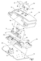
- FIG. 1 is an exploded view of an inventive Wegverstellschalter shown, wherein designated by the reference numeral 10 is a switch housing.
- the switch housing 10 is closed by a housing bottom, not shown, on which a circuit board 16 is mounted, which carries a four-quadrant switch 18.
- a holder 20 is also placed, which is secured by suitable means, such as screws or latches.
- This holder 20 serves to receive a link 22, which is formed by a first slider 24 and a second slider 26.
- the first slider 24 engages in a slot guide 28 in the holder 20 and has locking elements 30, via which it is held locked in the holder 20.
- the first slider 24 also has a transverse slot 32 in which the second slider 26 is slidably mounted in the transverse direction.
- the engaging in the first slide 24 pin of the second slider 26 has in the region of its free end spherical surfaces 12, whereby the second slide 26 is optimally coupled regardless of its spatial position with the first slide 24. In the longitudinal direction, the second slider 26 is coupled for movement with the first slider 24.
- the first slider 24 also has a receiving mandrel 34, on which a retaining spring 36 is latched.
- This retaining spring 36 serves to receive a first button 38, which can be moved in the longitudinal direction (double arrow 40).
- a longitudinal slot 42 is provided in the switch housing 10, in which the retaining spring 38 engages and is supported by retaining arms 44 which hold the first button 38 in a central position.
- the second slider 26 has a longitudinal slot 46, in which a pin 48 engages, which protrudes from a second button 50 in the direction of the link 22.
- This pin 48 has at its free end also spherical surfaces 14, via which it engages in the longitudinal slot 46 of the second slider 26.
- the second key 50 is pivotable in the direction of the arrows 56 via a pivot pin 52, which is held pivotably in a bearing 54.
- the pin 48 is moved in a transverse slot 58 of the switch housing 10.
- the button 38 is moved in one of the directions of the double arrow 40, then the first slider 24 is displaced in the longitudinal direction and taken over the transverse slot 32 of the second slider 26, so that the actuating pin 60 of the Four-quadrant switch 18 is also operated, but in a direction orthogonal to the previous direction.
- the switch housing 10 has a slightly curved top, which is adapted to the outer contour of the interior. Despite this curved surface, the movements of the two buttons 38 and 50 can be easily transferred to the two slides 24 and 26 and thus to the four-quadrant switch 18. In addition, it is easy to see that the Wegverstellschalter is composed of a small number of components.
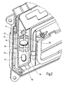
- the second slider 26 has on its upper side two upwardly projecting in the direction of the switch housing 10 pin 44. These two pins 44 each engage in a cross slide 46, which at the in the FIG. 2 shown underside of the switch housing 10 is provided.
- Each cross slide 46 is formed by a longitudinal slot 62 and a transverse slot 64, which form a cross center 66 at the intersection.
- the pins 44 are each in the middle of the cross 66.
- the button 38 is actuated, the pins 44 move in the longitudinal slots 62 of the Buchkulissen 46. Now a simultaneous operation of the button 50 is not possible because of lateral Dodge is prevented by the Buchkulissen 46. If the button 50 is first actuated from the rest position, then the pins 44 move in the two transverse slots 64. A simultaneous actuation of the button 38 is not possible.
Landscapes
- Engineering & Computer Science (AREA)
- Human Computer Interaction (AREA)
- Aviation & Aerospace Engineering (AREA)
- Transportation (AREA)
- Mechanical Engineering (AREA)
- Switches With Compound Operations (AREA)
- Seats For Vehicles (AREA)
- Toilet Supplies (AREA)
- Chairs Characterized By Structure (AREA)
- Chairs For Special Purposes, Such As Reclining Chairs (AREA)
Claims (14)
- Interrupteur de réglage de siège pour un véhicule automobile comprenant deux touches (38, 50), dont l'une (38) et l'autre (50) sont montées sur un boîtier d'interrupteur (10) de façon à pouvoir être actionnées respectivement dans la direction longitudinale et principalement dans la direction transversale, caractérisé en ce que les touches (38, 50) sont reliées par une coulisse (22) à un interrupteur à quatre quadrants (18).
- Interrupteur de réglage de siège selon la revendication 1, caractérisé en ce que le mouvement de réglage d'une touche (38 ou 50) est dissocié de l'autre touche (50 ou 38) par l'intermédiaire de la coulisse (22).
- Interrupteur de réglage de siège selon l'une quelconque des revendications précédentes, caractérisé en ce que la coulisse (22) présente un premier curseur (24) relié à la première touche (38) et un second curseur (26) relié à la seconde touche (50).
- Interrupteur de réglage de siège selon la revendication 3, caractérisé en ce que le second curseur (26) est monté avec une fente transversale (32) dans le premier curseur (24) de façon déplaçable dans la direction transversale (56).
- Interrupteur de réglage de siège selon la revendication 3 ou 4, caractérisé en ce que le second curseur (26) est relié directement à l'interrupteur à quatre quadrants (18).
- Interrupteur de réglage de siège selon l'une quelconque des revendications 3 à 5, caractérisé en ce que le second curseur (26) présente une fente longitudinale (46), dans laquelle un tenon (48) de la seconde touche (50) est monté de façon déplaçable dans la direction longitudinale (40).
- Interrupteur de réglage de siège selon l'une quelconque des revendications 3 à 6, caractérisé en ce que le premier curseur (24) est guidé de façon coulissante dans la direction longitudinale (40) dans un support (20) fixe par rapport à l'interrupteur à quatre quadrants (18).
- Interrupteur de réglage de siège selon l'une quelconque des revendications précédentes, caractérisé en ce que les plans de coulissement des touches (38, 50) se coupent en formant un angle différent de zéro degré.
- Interrupteur de réglage de siège selon l'une quelconque des revendications 3 à 8, caractérisé en ce que la première touche (38) est maintenue encliquetée sur le premier curseur (24) et/ou le tenon (48) de la seconde touche (50) dans le second curseur (26) et/ou le second curseur (26) sur l'interrupteur à quatre quadrants (18) et/ou le premier curseur (24) dans le support (20).
- Interrupteur de réglage de siège selon l'une quelconque des revendications précédentes, caractérisé en ce que la coulisse (22) est guidée dans une coulisse en croix (46) fixe.
- Interrupteur de réglage de siège selon la revendication 10, caractérisé en ce que la coulisse en croix (46) est prévue sur le côté inférieur du boîtier d'interrupteur (10).
- Interrupteur de réglage de siège selon la revendication 10 ou 11, caractérisé en ce que la coulisse en croix (46) présente au moins une fente longitudinale (62) et au moins une fente transversale (64).
- Interrupteur de réglage de siège selon la revendication 12, caractérisé en ce que la coulisse (22) présente au moins un tenon (44) et en ce que le ou les tenons (44) reposent dans la position de repos au point ou aux points d'intersection des fentes (62 et 64) de la coulisse en croix (46).
- Interrupteur de réglage de siège selon l'une quelconque des revendications 10 à 13, caractérisé en ce qu'un actionnement simultané des touches (38 et 50) est empêché par la coulisse en croix (66).
Applications Claiming Priority (2)
| Application Number | Priority Date | Filing Date | Title |
|---|---|---|---|
| DE10307911 | 2003-02-19 | ||
| DE10307911A DE10307911A1 (de) | 2003-02-19 | 2003-02-19 | Sitzverstellschalter |
Publications (3)
| Publication Number | Publication Date |
|---|---|
| EP1452385A2 EP1452385A2 (fr) | 2004-09-01 |
| EP1452385A3 EP1452385A3 (fr) | 2007-01-17 |
| EP1452385B1 true EP1452385B1 (fr) | 2008-04-23 |
Family
ID=32748041
Family Applications (1)
| Application Number | Title | Priority Date | Filing Date |
|---|---|---|---|
| EP04400004A Expired - Lifetime EP1452385B1 (fr) | 2003-02-19 | 2004-02-12 | Commutateur de réglage de siège |
Country Status (3)
| Country | Link |
|---|---|
| EP (1) | EP1452385B1 (fr) |
| AT (1) | ATE393050T1 (fr) |
| DE (2) | DE10307911A1 (fr) |
Families Citing this family (1)
| Publication number | Priority date | Publication date | Assignee | Title |
|---|---|---|---|---|
| ATE449700T1 (de) | 2006-05-24 | 2009-12-15 | Delphi Tech Inc | Schalteranordnung, insbesondere zur verstellung eines fahrzeugsitzes |
Family Cites Families (8)
| Publication number | Priority date | Publication date | Assignee | Title |
|---|---|---|---|---|
| US4678872A (en) * | 1986-09-10 | 1987-07-07 | United Techologies Automotive, Inc. | Button set and switch |
| DE3927037A1 (de) * | 1989-08-16 | 1991-02-28 | Kostal Leopold Gmbh & Co Kg | Elektrische schalteranordnung |
| DE4137888A1 (de) * | 1991-11-18 | 1993-05-19 | Kostal Leopold Gmbh & Co Kg | Elektrische schalteranordnung fuer die stellantriebe von fahrzeugsitzteilen |
| JP3673339B2 (ja) * | 1996-09-30 | 2005-07-20 | アルプス電気株式会社 | スイッチ装置 |
| DE19728743C1 (de) * | 1997-07-04 | 1998-06-25 | Kostal Leopold Gmbh & Co Kg | Steuereinrichtung |
| DE19729866B4 (de) * | 1997-07-11 | 2006-06-14 | Bayerische Motoren Werke Ag | Schalteranordnung für einen durch Fremdkraft verstellbaren Fahrzeugsitz |
| DE19844333C1 (de) * | 1998-09-28 | 1999-09-30 | Kostal Leopold Gmbh & Co Kg | Elektrischer Sitzverstellschalter |
| DE10046748C1 (de) * | 2000-09-21 | 2001-11-15 | Kostal Leopold Gmbh & Co Kg | Wipptastenanordnung |
-
2003
- 2003-02-19 DE DE10307911A patent/DE10307911A1/de not_active Withdrawn
-
2004
- 2004-02-12 DE DE502004006876T patent/DE502004006876D1/de not_active Expired - Lifetime
- 2004-02-12 AT AT04400004T patent/ATE393050T1/de not_active IP Right Cessation
- 2004-02-12 EP EP04400004A patent/EP1452385B1/fr not_active Expired - Lifetime
Also Published As
| Publication number | Publication date |
|---|---|
| ATE393050T1 (de) | 2008-05-15 |
| DE502004006876D1 (de) | 2008-06-05 |
| EP1452385A3 (fr) | 2007-01-17 |
| DE10307911A1 (de) | 2004-09-02 |
| EP1452385A2 (fr) | 2004-09-01 |
Similar Documents
| Publication | Publication Date | Title |
|---|---|---|
| DE102017211720B4 (de) | Sitzaufbau mit einem einstellbaren Kopfstützenaufbau | |
| DE19507952C2 (de) | Schaltvorrichtung | |
| EP2053623B1 (fr) | Dispositif de commutation | |
| DE69929668T2 (de) | Drehbarer Sitz, insbesondere für ein Schienenfahrzeug | |
| EP1848903B1 (fr) | Dispositif electrique de changement de vitesse pour un vehicule automobile | |
| DE69615624T2 (de) | Getriebeschalthebel | |
| DE602004009270T2 (de) | Eine höhenverstellbare Armlehne für eine Kraftfahrzeugtür | |
| EP2184754B1 (fr) | Interrupteur | |
| DE10361716A1 (de) | In ein Fahrzeuglenkrad eingebaute Fernsteuertastenanordnung | |
| DE112021005534T5 (de) | Basisstruktur, die für einen sitzkörper eines kindersicherheitssitzes eingerichtet ist | |
| DE102019202168A1 (de) | Entriegelungshebel für gleitvorrichtung | |
| DE19743307A1 (de) | Schalteinrichtung | |
| EP1611375B1 (fr) | Changement de vitesses du type shift-by-wire avec position p | |
| DE202018103666U1 (de) | Verstellbare Kopfstütze für einen Fahrzeugsitz | |
| WO2022174937A1 (fr) | Siège de véhicule et procédé d'assemblage | |
| EP1452385A2 (fr) | Commutateur de réglage de siège | |
| DE69603900T2 (de) | Gelenk zur Verstellung des Neigungswinkels einer Fahrzeugsitzrückenlehne | |
| DE102019007900B4 (de) | Multifunktionsschalter | |
| EP2228811A2 (fr) | Insert de commutateur d'un appareil d'installation électrique | |
| DE2922637A1 (de) | Abstimmeinrichtung | |
| DE2109672A1 (de) | Abstimmechanismus mit fünf Druckknöpfen und zehn Wahlmöglichkeiten für den Einsatz in einem AM/FM-Rundfunkempfänger | |
| DE102024132638A1 (de) | Schienenanordnung | |
| EP1428717B1 (fr) | Commutateur de réglage de siège | |
| DE19955326B4 (de) | Bedieneinrichtung für die Verstellung eines Fahrzeugsitzes | |
| EP1528870A1 (fr) | Dispositif de nettoyage de la tete rasante d'un rasoir electrique |
Legal Events
| Date | Code | Title | Description |
|---|---|---|---|
| PUAI | Public reference made under article 153(3) epc to a published international application that has entered the european phase |
Free format text: ORIGINAL CODE: 0009012 |
|
| AK | Designated contracting states |
Kind code of ref document: A2 Designated state(s): AT BE BG CH CY CZ DE DK EE ES FI FR GB GR HU IE IT LI LU MC NL PT RO SE SI SK TR |
|
| AX | Request for extension of the european patent |
Extension state: AL HR LT LV MK |
|
| RIN1 | Information on inventor provided before grant (corrected) |
Inventor name: MAHLER, REINHARD Inventor name: ALBRECHT, CHRISTIAN Inventor name: PETZOLD, MANUEL |
|
| PUAL | Search report despatched |
Free format text: ORIGINAL CODE: 0009013 |
|
| AK | Designated contracting states |
Kind code of ref document: A3 Designated state(s): AT BE BG CH CY CZ DE DK EE ES FI FR GB GR HU IE IT LI LU MC NL PT RO SE SI SK TR |
|
| AX | Request for extension of the european patent |
Extension state: AL LT LV MK |
|
| 17P | Request for examination filed |
Effective date: 20070307 |
|
| AKX | Designation fees paid |
Designated state(s): AT BE BG CH CY CZ DE DK EE ES FI FR GB GR HU IE IT LI LU MC NL PT RO SE SI SK TR |
|
| GRAP | Despatch of communication of intention to grant a patent |
Free format text: ORIGINAL CODE: EPIDOSNIGR1 |
|
| GRAC | Information related to communication of intention to grant a patent modified |
Free format text: ORIGINAL CODE: EPIDOSCIGR1 |
|
| GRAS | Grant fee paid |
Free format text: ORIGINAL CODE: EPIDOSNIGR3 |
|
| GRAA | (expected) grant |
Free format text: ORIGINAL CODE: 0009210 |
|
| AK | Designated contracting states |
Kind code of ref document: B1 Designated state(s): AT BE BG CH CY CZ DE DK EE ES FI FR GB GR HU IE IT LI LU MC NL PT RO SE SI SK TR |
|
| REG | Reference to a national code |
Ref country code: GB Ref legal event code: FG4D Free format text: NOT ENGLISH |
|
| REG | Reference to a national code |
Ref country code: CH Ref legal event code: EP |
|
| REF | Corresponds to: |
Ref document number: 502004006876 Country of ref document: DE Date of ref document: 20080605 Kind code of ref document: P |
|
| REG | Reference to a national code |
Ref country code: IE Ref legal event code: FG4D Free format text: LANGUAGE OF EP DOCUMENT: GERMAN |
|
| REG | Reference to a national code |
Ref country code: SE Ref legal event code: TRGR |
|
| PG25 | Lapsed in a contracting state [announced via postgrant information from national office to epo] |
Ref country code: SI Free format text: LAPSE BECAUSE OF FAILURE TO SUBMIT A TRANSLATION OF THE DESCRIPTION OR TO PAY THE FEE WITHIN THE PRESCRIBED TIME-LIMIT Effective date: 20080423 |
|
| NLV1 | Nl: lapsed or annulled due to failure to fulfill the requirements of art. 29p and 29m of the patents act | ||
| PG25 | Lapsed in a contracting state [announced via postgrant information from national office to epo] |
Ref country code: PT Free format text: LAPSE BECAUSE OF FAILURE TO SUBMIT A TRANSLATION OF THE DESCRIPTION OR TO PAY THE FEE WITHIN THE PRESCRIBED TIME-LIMIT Effective date: 20080923 Ref country code: NL Free format text: LAPSE BECAUSE OF FAILURE TO SUBMIT A TRANSLATION OF THE DESCRIPTION OR TO PAY THE FEE WITHIN THE PRESCRIBED TIME-LIMIT Effective date: 20080423 Ref country code: BG Free format text: LAPSE BECAUSE OF FAILURE TO SUBMIT A TRANSLATION OF THE DESCRIPTION OR TO PAY THE FEE WITHIN THE PRESCRIBED TIME-LIMIT Effective date: 20080723 Ref country code: ES Free format text: LAPSE BECAUSE OF FAILURE TO SUBMIT A TRANSLATION OF THE DESCRIPTION OR TO PAY THE FEE WITHIN THE PRESCRIBED TIME-LIMIT Effective date: 20080803 Ref country code: FI Free format text: LAPSE BECAUSE OF FAILURE TO SUBMIT A TRANSLATION OF THE DESCRIPTION OR TO PAY THE FEE WITHIN THE PRESCRIBED TIME-LIMIT Effective date: 20080423 |
|
| REG | Reference to a national code |
Ref country code: IE Ref legal event code: FD4D |
|
| ET | Fr: translation filed | ||
| PG25 | Lapsed in a contracting state [announced via postgrant information from national office to epo] |
Ref country code: IE Free format text: LAPSE BECAUSE OF FAILURE TO SUBMIT A TRANSLATION OF THE DESCRIPTION OR TO PAY THE FEE WITHIN THE PRESCRIBED TIME-LIMIT Effective date: 20080423 Ref country code: DK Free format text: LAPSE BECAUSE OF FAILURE TO SUBMIT A TRANSLATION OF THE DESCRIPTION OR TO PAY THE FEE WITHIN THE PRESCRIBED TIME-LIMIT Effective date: 20080423 Ref country code: CZ Free format text: LAPSE BECAUSE OF FAILURE TO SUBMIT A TRANSLATION OF THE DESCRIPTION OR TO PAY THE FEE WITHIN THE PRESCRIBED TIME-LIMIT Effective date: 20080423 |
|
| PG25 | Lapsed in a contracting state [announced via postgrant information from national office to epo] |
Ref country code: RO Free format text: LAPSE BECAUSE OF FAILURE TO SUBMIT A TRANSLATION OF THE DESCRIPTION OR TO PAY THE FEE WITHIN THE PRESCRIBED TIME-LIMIT Effective date: 20080423 Ref country code: SK Free format text: LAPSE BECAUSE OF FAILURE TO SUBMIT A TRANSLATION OF THE DESCRIPTION OR TO PAY THE FEE WITHIN THE PRESCRIBED TIME-LIMIT Effective date: 20080423 |
|
| PLBE | No opposition filed within time limit |
Free format text: ORIGINAL CODE: 0009261 |
|
| STAA | Information on the status of an ep patent application or granted ep patent |
Free format text: STATUS: NO OPPOSITION FILED WITHIN TIME LIMIT |
|
| 26N | No opposition filed |
Effective date: 20090126 |
|
| PG25 | Lapsed in a contracting state [announced via postgrant information from national office to epo] |
Ref country code: EE Free format text: LAPSE BECAUSE OF FAILURE TO SUBMIT A TRANSLATION OF THE DESCRIPTION OR TO PAY THE FEE WITHIN THE PRESCRIBED TIME-LIMIT Effective date: 20080423 |
|
| BERE | Be: lapsed |
Owner name: VALEO SCHALTER UND SENSOREN G.M.B.H. Effective date: 20090228 |
|
| PGFP | Annual fee paid to national office [announced via postgrant information from national office to epo] |
Ref country code: SE Payment date: 20090120 Year of fee payment: 6 |
|
| PG25 | Lapsed in a contracting state [announced via postgrant information from national office to epo] |
Ref country code: MC Free format text: LAPSE BECAUSE OF NON-PAYMENT OF DUE FEES Effective date: 20090228 |
|
| REG | Reference to a national code |
Ref country code: CH Ref legal event code: PL |
|
| GBPC | Gb: european patent ceased through non-payment of renewal fee |
Effective date: 20090212 |
|
| PG25 | Lapsed in a contracting state [announced via postgrant information from national office to epo] |
Ref country code: LI Free format text: LAPSE BECAUSE OF NON-PAYMENT OF DUE FEES Effective date: 20090228 Ref country code: CH Free format text: LAPSE BECAUSE OF NON-PAYMENT OF DUE FEES Effective date: 20090228 |
|
| PG25 | Lapsed in a contracting state [announced via postgrant information from national office to epo] |
Ref country code: BE Free format text: LAPSE BECAUSE OF NON-PAYMENT OF DUE FEES Effective date: 20090228 |
|
| PG25 | Lapsed in a contracting state [announced via postgrant information from national office to epo] |
Ref country code: GB Free format text: LAPSE BECAUSE OF NON-PAYMENT OF DUE FEES Effective date: 20090212 |
|
| PG25 | Lapsed in a contracting state [announced via postgrant information from national office to epo] |
Ref country code: AT Free format text: LAPSE BECAUSE OF NON-PAYMENT OF DUE FEES Effective date: 20090212 |
|
| EUG | Se: european patent has lapsed | ||
| PG25 | Lapsed in a contracting state [announced via postgrant information from national office to epo] |
Ref country code: GR Free format text: LAPSE BECAUSE OF FAILURE TO SUBMIT A TRANSLATION OF THE DESCRIPTION OR TO PAY THE FEE WITHIN THE PRESCRIBED TIME-LIMIT Effective date: 20080724 |
|
| PG25 | Lapsed in a contracting state [announced via postgrant information from national office to epo] |
Ref country code: LU Free format text: LAPSE BECAUSE OF NON-PAYMENT OF DUE FEES Effective date: 20090212 |
|
| PG25 | Lapsed in a contracting state [announced via postgrant information from national office to epo] |
Ref country code: HU Free format text: LAPSE BECAUSE OF FAILURE TO SUBMIT A TRANSLATION OF THE DESCRIPTION OR TO PAY THE FEE WITHIN THE PRESCRIBED TIME-LIMIT Effective date: 20081024 |
|
| PG25 | Lapsed in a contracting state [announced via postgrant information from national office to epo] |
Ref country code: TR Free format text: LAPSE BECAUSE OF FAILURE TO SUBMIT A TRANSLATION OF THE DESCRIPTION OR TO PAY THE FEE WITHIN THE PRESCRIBED TIME-LIMIT Effective date: 20080423 |
|
| PG25 | Lapsed in a contracting state [announced via postgrant information from national office to epo] |
Ref country code: CY Free format text: LAPSE BECAUSE OF FAILURE TO SUBMIT A TRANSLATION OF THE DESCRIPTION OR TO PAY THE FEE WITHIN THE PRESCRIBED TIME-LIMIT Effective date: 20080423 |
|
| PG25 | Lapsed in a contracting state [announced via postgrant information from national office to epo] |
Ref country code: SE Free format text: LAPSE BECAUSE OF NON-PAYMENT OF DUE FEES Effective date: 20100213 |
|
| REG | Reference to a national code |
Ref country code: FR Ref legal event code: PLFP Year of fee payment: 13 |
|
| REG | Reference to a national code |
Ref country code: FR Ref legal event code: PLFP Year of fee payment: 14 |
|
| REG | Reference to a national code |
Ref country code: FR Ref legal event code: PLFP Year of fee payment: 15 |
|
| PGFP | Annual fee paid to national office [announced via postgrant information from national office to epo] |
Ref country code: FR Payment date: 20230227 Year of fee payment: 20 |
|
| PGFP | Annual fee paid to national office [announced via postgrant information from national office to epo] |
Ref country code: IT Payment date: 20230208 Year of fee payment: 20 Ref country code: DE Payment date: 20230207 Year of fee payment: 20 |
|
| P01 | Opt-out of the competence of the unified patent court (upc) registered |
Effective date: 20230528 |
|
| REG | Reference to a national code |
Ref country code: DE Ref legal event code: R071 Ref document number: 502004006876 Country of ref document: DE |