EP1450995B1 - Positionierhilfe - Google Patents
Positionierhilfe Download PDFInfo
- Publication number
- EP1450995B1 EP1450995B1 EP02790468A EP02790468A EP1450995B1 EP 1450995 B1 EP1450995 B1 EP 1450995B1 EP 02790468 A EP02790468 A EP 02790468A EP 02790468 A EP02790468 A EP 02790468A EP 1450995 B1 EP1450995 B1 EP 1450995B1
- Authority
- EP
- European Patent Office
- Prior art keywords
- positioning aid
- aid according
- retaining
- casing
- magnet
- Prior art date
- Legal status (The legal status is an assumption and is not a legal conclusion. Google has not performed a legal analysis and makes no representation as to the accuracy of the status listed.)
- Expired - Lifetime
Links
Images


Classifications
-
- B—PERFORMING OPERATIONS; TRANSPORTING
- B28—WORKING CEMENT, CLAY, OR STONE
- B28B—SHAPING CLAY OR OTHER CERAMIC COMPOSITIONS; SHAPING SLAG; SHAPING MIXTURES CONTAINING CEMENTITIOUS MATERIAL, e.g. PLASTER
- B28B7/00—Moulds; Cores; Mandrels
- B28B7/0002—Auxiliary parts or elements of the mould
- B28B7/0014—Fastening means for mould parts, e.g. for attaching mould walls on mould tables; Mould clamps
- B28B7/0017—Fastening means for mould parts, e.g. for attaching mould walls on mould tables; Mould clamps for attaching mould walls on mould tables
-
- B—PERFORMING OPERATIONS; TRANSPORTING
- B28—WORKING CEMENT, CLAY, OR STONE
- B28B—SHAPING CLAY OR OTHER CERAMIC COMPOSITIONS; SHAPING SLAG; SHAPING MIXTURES CONTAINING CEMENTITIOUS MATERIAL, e.g. PLASTER
- B28B7/00—Moulds; Cores; Mandrels
- B28B7/0002—Auxiliary parts or elements of the mould
- B28B7/0014—Fastening means for mould parts, e.g. for attaching mould walls on mould tables; Mould clamps
- B28B7/002—Fastening means for mould parts, e.g. for attaching mould walls on mould tables; Mould clamps using magnets
-
- Y—GENERAL TAGGING OF NEW TECHNOLOGICAL DEVELOPMENTS; GENERAL TAGGING OF CROSS-SECTIONAL TECHNOLOGIES SPANNING OVER SEVERAL SECTIONS OF THE IPC; TECHNICAL SUBJECTS COVERED BY FORMER USPC CROSS-REFERENCE ART COLLECTIONS [XRACs] AND DIGESTS
- Y10—TECHNICAL SUBJECTS COVERED BY FORMER USPC
- Y10S—TECHNICAL SUBJECTS COVERED BY FORMER USPC CROSS-REFERENCE ART COLLECTIONS [XRACs] AND DIGESTS
- Y10S425/00—Plastic article or earthenware shaping or treating: apparatus
- Y10S425/033—Magnet
Definitions
- the present invention relates to a positioning aid having a magnet means for positioning a formwork means, the magnet means being movable between a use position in which the magnet means is in contact with a ferromagnetic formwork support and a non-use position in which the magnet means is spaced from the formwork support is, with at least one holding device against which the magnetic device is supported against a holding force of the magnetic device and with at least one resilient support means for generating a lifting force against the holding force to hold the magnetic device in the non-use position.
- Such a positioning aid for magnetic devices for positioning a formwork device is z. B. from EP 0 842 339.
- the magnetic device consists of a permanent magnet, which is received in a holding device.
- the holding device is integrated into formwork parts of the formwork system and has a magnet over the lifting hook, which rests on the formwork support.
- a spring which forms the support means and exerts the lifting force on the magnet.
- the magnet In the position of use, the magnet is in contact with the ferromagnetic formwork underlay. Due to the holding force of the magnet on the formwork support slipping of the magnet is prevented, so that the formwork parts can be positioned on the formwork base with the magnet.
- the holding force of the magnet overcomes the lifting force of the spring. If the magnet is to be moved, the magnet is lifted off the shuttering pad by means of a jacking screw. Once the magnet is spaced from the formwork pad, the holding force exerted by the magnet on the formwork pad decreases sharply. In the non-use position, so with the magnet raised, the lifting force of the spring is such that it overcomes the remaining holding force between the magnet and shuttering pad and the weight of the magnet itself, so that the magnet dwells in the non-use position. The positioning aid can then be moved to a new location.
- the magnet is pressed to the formwork support until the holding force and the weight of the magnet overcome the lifting force of the spring and the magnet automatically comes into contact with the formwork underlay.
- the force to return the magnet from its non-use position into the use position can, for. B. done by a blow to the fixture.
- the known positioning aid proves to be quite expensive, both in terms of their space requirements, as well as their production costs. In addition, it can not be used flexibly, since the application is determined by the existing magnet. If finer contours to be limited to the formwork elements on the formwork base, or large holding forces for larger formwork elements are required, the known positioning aids often can not be used
- the object of the invention is therefore to provide a cost-effective solution for positioning, which can be used universally.
- the object of the invention is achieved in that the magnetic device firmly connected to the holding device and the support means is at least partially disposed between the holding device and shuttering support at least in the non-use position.
- This solution is simple and has the advantage that the support device no longer has to be arranged above the magnetic device and thereby builds the positioning aid substantially flatter.
- the support device can now be attached to the side of the magnetic device. As a result, you are no longer limited by the design of the lift bar in the field of application of positioning. It is thus possible to adapt the holding device to the dimensions of the magnetic device.
- At least two spaced-apart holding device are provided, each of which is assigned at least one support means.
- an adaptation of the holding devices to the magnetic device of different dimensions can be made in a modular manner.
- the holding devices are arranged on opposite sides of the magnetic device. This allows a uniform support of the magnetic device realize.
- magnetic device In a substantially rectangular in plan view magnetic device can be a very uniform support of the magnetic device on all four sides realize. Especially with very long substantially rectangular magnetic devices, such a design may prove advantageous in order to avoid misaligned.
- each case two holding devices can be assigned to one side of the magnetic device. This also makes it possible to realize a uniform support of the magnetic device.
- the holding devices can in this case be provided near the corners of a quadrangular or rectangular holding device which is quadrangular in plan view. It may be advantageous if the holding devices are attached to the longer sides of a rectangular in plan view magnetic device.
- the holding devices can be spaced apart by associated adjusting mechanisms. As a result, the holding devices can be more easily adapted to the respective magnetic devices.
- each of two holding devices can be rigidly connected to each other, thereby forming two holding elements.
- the holding devices form a holding frame surrounding the magnetic device with the adjusting devices. This also makes it possible to realize a secure connection between the magnetic device and holding device.
- the holding means may be releasably connectable to the magnetic means.
- the magnetic device is substantially parallelepiped with an underside facing the formwork support.
- an adaptation of the holding devices to the magnetic device can be easily realized.
- the holding device can be attached to one of the side walls of the magnetic device. This makes it possible to realize a particularly flat positioning positioning aid.
- the holding device is attached to an upper side of the magnetic device facing away from the formwork side.
- the holding devices may have receptacles into which the magnetic device engages.
- the magnetic device can be inserted into the receptacles.
- the magnetic devices and the recordings are simply plugged into each other and z. B. secured by simple grub screws against each other. This results in a significantly simplified installation.
- the holding device is attached by means of a screw connection to the magnetic device.
- a secure connection between the magnetic device and the holding device can be ensured in a simple manner.
- a lifting device may be provided, by means of which the magnetic device from its use in the non-use position is convertible. As a result, the lifting of the magnetic device can be facilitated.
- the lifting device is attached to the magnetic device. Then it is not necessary to attach the lifting device to the holding device, so that the holding device can be made simpler. In addition, the entire positioning aid can be more compact.
- a particularly simple, yet effective lifting device can be provided if the lifting device has an eccentric which can be brought into engagement with the formwork support for transferring the magnetic device from the use position into the non-use position.
- lever and the eccentric are fixedly connected to each other rotatably mounted on the magnet device.
- the eccentric is arranged closer to the side of the magnetic device than on the side opposite this side. As a result, the eccentric acts asymmetrically when lifting the magnetic device. The forces to be lifted can be reduced in this way.
- the support means for generating the lifting force may comprise an elastic spring element. This makes it possible to realize a very simple support device.
- the elastic spring element may be a compression spring.
- Compression springs allow great forces and are cost-effective components.
- the elastic spring element may comprise an elastomer.
- elastomers can be realized very simple and inexpensive spring elements.
- the elastomer may be a rubber. Even so, permanently elastic and inexpensive spring elements can be realized.
- the elastic spring element may comprise a plastic spring.
- the support device and the holding device can then be designed to reduce weight.
- a particularly compact design of the positioning can be achieved when the elastic spring element is a bending plate, the end portion is spread when passing from the non-use position to the use position by sliding on the formwork support.
- the support means may comprise a rearing device which is slidably mounted in the holding device and which rests at least in the non-use position on the formwork support, wherein the spring means is received between the rearing device and the support means.
- the support means can be designed in the manner of a piston-cylinder device, wherein the Aufstands coupled forms a displaceable piston.
- the Aufstandsseihraum is substantially cup-shaped and the recording of the holding device is cylinder jacket-shaped.
- the receiving device it can also serve as a guide element for the spring device.
- the uprising device can be connected to the holding device captive.
- the spring force of the spring device can be adjustable. It may turn out to be advantageous if an adjusting screw is provided for adjusting the spring force. This results in a simple adjustment. It is also conceivable if the spring device itself has a setting thread. Then by turning the spring device itself, the setting be made. Accordingly, a thread-like receptacle must be provided in the holding device.
- the holding device can be integrated into the magnetic device. This makes it possible to realize a particularly compact construction of the positioning aid together with the magnetic device.
- the holding devices are formed by holes in the magnet device. This allows a very simple design of the holding device.
- the holding device is connected by gluing with the magnetic device. As a result, a particularly simple and inexpensive construction can be realized.
- the formwork device and the holding device are integrally formed. Then, the holding device can be produced together with the formwork device in one operation.
- the magnetic device and the formwork device are firmly connected to each other. This gives a stable and compact design of shuttering and magnetic device.
- the magnet can be safely anchored in the formwork device.
- the formwork device is spaced from the formwork support. Then the formwork device can be moved easily on a formwork support and a given position. The shuttering then rests only on one or more support means.
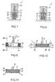
- FIG. 1 shows the positioning means 1 according to the invention together with a magnetic device 2, on which a lifting device 3 is provided.
- the positioning aid 1 forms together with the magnetic device 2 a modular system and can also form a formwork element.
- the magnetic device 2 is a permanent magnet of substantially parallelepiped-shaped design with a substantially planar underside 4 and a top 5 parallel thereto and side surfaces 6 arranged at right angles to each other between top and bottom. In the plan view, the magnetic device is substantially square.
- the magnetic device 2 with its underside 4 is in contact with a ferromagnetic shuttering pad. 7
- FIG. 1 The use position is shown in FIG. In a non-use position shuttering pad 7 and bottom 4 are spaced from each other, as shown in Figure 1.
- a rod-shaped handling device 8 by means of which the magnetic device 2 can be moved on the shuttering pad 7, if the magnetic device 2 is in its non-use position. Likewise, with this handling device 8, the magnetic device 2 can be transferred from its non-use to the use position.
- a bearing pin 9 is provided, on which an eccentric 10 is rotatably mounted with a lever 11 attached thereto pivotally.
- the eccentric is in engagement with the shuttering pad 7, wherein by pressing the lever 11, the magnetic device 2 from their use in their non-use position can be transferred.
- the bearing pin 9 is closer to the left end of the associated side surface 6, so that the eccentric is substantially in a corner of the magnetic device with the shuttering pad 7 is engageable.
- the holding devices 12 are also attached to the magnetic device 2, two holding devices 12 each being assigned to one side surface 6.
- the holding devices 12 are arranged on opposite sides of the magnetic device 2.
- the holding devices 12 may be e.g. be attached by means of a screw, not shown, or by gluing to the magnetic device 2.
- the holding devices 12 can be detachably connected to the magnet device 2. During operation of the positioning aid, however, the holding devices 12 are rigidly connected to the magnet device 2.
- Each of the holding devices 12 has in each case a support device 13, which has a cup-shaped rearing device 14 and a spring device 15.
- the rearing device 14 has a cylindrical outer surface 16, which is received in an axially displaceable manner in a cylindrical inner surface 17 of the holding device 12.
- the spring device 15 has an elastomeric spring element 18 made of rubber, which has threaded bolts 19 and 20 at its two ends, wherein the threaded bolt 19 in a threaded bore 21, the rearing device 14 and the threaded bolt 20 is received in a threaded bore 22 of the holding device 12.
- uprising device 14 and spring element 18 are captively connected to the holding device 12.
- FIG. 5 shows the support device 13 in a state in which the magnet device 2 is in a non-use position.
- the rearing device 14 projects with the support surface 23 with respect to the holding device 12.
- the support surface 23 rests on the shuttering pad 7.
- FIG. 6 shows a state of the support device 13 in which the magnet device 2 is in its position of use.
- the spring device 15 is compressed in the position of use of the magnetic device 2.
- the spring device 15 operates as a compression spring, thus generating a lifting force, which counteracts the holding force of the magnet in its position of use. In the position of use of the magnetic device, however, the lifting force is significantly lower than the holding force of the magnetic device. The magnetic device 2 is thereby firmly against the shuttering pad 7. In the non-use position, the magnetic device 2 is spaced from the shuttering pad 7, so that the holding force generated by the magnet has been significantly reduced.
- the lifting force applied by the spring device 15 is dimensioned such that in the non-use position of the shuttering pad 7, the lifting force is greater than the remaining residual holding force of the magnetic device 2 and the weight of the magnetic device 2, so that the holding force is sufficient to the magnetic device 2 in the non-use position to keep.
- the spring device can also be designed so that in the non-use position only the rearing device protrudes from the underside of the magnetic device and the spring device ends above the underside of the magnetic device. As a result, the spring device is arranged only laterally of the magnetic device. However, it is preferred that also the spring device ends below the underside of the magnetic device in the non-use position. This results in the more compact design of the positioning according to the invention.
- the positioning aid is moved together with the magnetic device 2 on the formwork support 7 to the desired location, wherein the magnetic device 2 is in the non-use position.
- a pressure force is applied in the direction of the formwork support 7 on the handling device 8, wherein this pressure force overcomes the holding force and the magnet device 2 is transferred together with the holding device from its non-use position to its position of use.
- the spring elements 18 are compressed in the spring device 15.
- the formwork elements can then be connected to the positioning aid or magnet device 2 in order to finish the formwork.
- the positioning aid can be made very compact.
- the holding device 12 due to its smooth-surfaced design, provides a positioning aid that is easily recognizable to the operator.
- the lower edge of the holding device 12 is only slightly above the formwork support 7, so that accurate positioning and alignment of the positioning aid and thus with the magnetic device 2, for example, along a predetermined line is possible.
- the holding devices can be attached to magnetic devices 2 of different dimensions. It is conceivable to provide a plurality of holding devices 12 in the case of a larger magnet device 2. It is also conceivable to attach the holding devices 12 at different points of the magnetic device 2, if this should be necessary due to the given space conditions.
- the holding devices 12 can thus be further spaced from each other or at a smaller distance from each other attached to the magnetic device. It is therefore possible to provide a kit consisting of magnetic devices 2 of different dimensions and thicknesses and a plurality of holding devices 12. The positioning aid can then be designed individually.
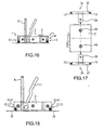
- FIGS 7 and 8 a second embodiment of the invention will be explained in more detail with reference to FIGS 7 and 8. To avoid repetition, the same elements are identified by the same reference numerals and only the differences from the first embodiment are explained.
- compression springs 24 made of steel or plastic are used.
- the holding device is shown with the support means when the magnetic device 2 is in the non-use position.
- the magnetic device 2 is in the position of use, so that the compression springs 24 are compressed.
- the rearing device 14 has a cover 25 with a bore 26 through which a plunger 27 extends with a stop 28 therethrough. By means of a screw the plunger 27 is fixedly attached to the holding device 12.
- the stopper 28, together with the cover 25, prevents the rearing device 14 from coming off the holding device 12.
- FIGS. 9, 10 and 11 A third embodiment of the invention is described in FIGS. 9, 10 and 11. Again, the same components are provided with the same reference numerals to avoid repetition. Only the differences are explained.
- the holding device 12 in the third embodiment consists of plate-shaped elements 29, which are attached to the magnetic device 2, between which a vertically extending towards the shuttering pad 7 spring plate 30 is received.
- the holding device 12 in the third embodiment consists of plate-shaped elements 29, which are attached to the magnetic device 2, between which a vertically extending towards the shuttering pad 7 spring plate 30 is received.
- Entab bainitese 31 of the spring plates when transferring the magnetic device from its non-use position in the use position shown in FIG 10 laterally spread. By this deformation they produce the necessary lifting power.
- the end portions 31 slide on the shuttering pad 7.
- the holding device supports in each case via the end portions 31 of the spring plates 30 on the shuttering pad 7.
- FIGS. 12, 13, 14 and 15 show a fourth embodiment of the invention.
- the mode of action corresponds to the first embodiment.
- the spring elements are designed in the same way.
- each connecting two holding devices 12 together.
- a combination of connecting plates 32, 33 and holding devices 12 forms a holding element 34.
- the two holding elements 34 can be pushed laterally onto the magnetic device 2 for mounting purposes.
- grub screws 35 which are each screwed into threaded holes 36, the holding elements 34 can be attached to the magnetic device 2 with a force fit.
- the two holding devices 12, together with the connecting plates 32 and 33 enclose the end sections of the magnetic device 2 in a substantially U-shaped manner.
- a fifth embodiment which also has retaining elements 34, in which, however, instead of connecting plates holding webs 37 each two holding devices 12 interconnect.
- An additional mounting plate 38 extends in sections along the upper side 5 of the magnetic device 2 and can be connected via a bore 39 and a screw 40 with the magnetic device 2.
- the screw 40 is located on the upper side 5 of the magnetic device 2. Due to the design of the holding web 37 and the holding devices 12, the holding element 34 lies flat against the associated side surface 6 of the magnetic device 2.
- compression springs are used.
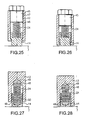
- FIGS. 18 and 19 illustrate a sixth embodiment of the invention.
- the holding device 12 is integrated in the magnet device 2. It is formed by blind holes 41, in each of which the support means 13 are received. This results in an additional compact design of the combination of magnetic device and positioning aid.
- a seventh embodiment of the invention is shown, whose operation and operation substantially corresponds to that of the third embodiment. From this embodiment has spring plates 30. However, serve as a holding element in this embodiment screws 42, with which the spring plates are attached to the magnetic device 2.
- FIG. 23 shows an eighth embodiment of the invention.
- a plurality of holding devices are integrally formed with a formwork device 41.
- the illustration in FIG. 23 is a sectional view in which two of the holding elements are visible.
- the formwork device is substantially parallelepiped-shaped with formwork sides 42 and a cover side 43 connecting the two formwork sides 42.
- the magnet device 2 is accommodated in a magnet receptacle 44.
- the magnetic device 2 is glued to the magnet holder 44.
- the bottom 4 of the magnetic device 2 is flush with the holding devices, or the formwork device 41 from.
- the construction of the support means 13 corresponds to z. Example, the construction of the first embodiment.
- the alternative described embodiments are also possible.
- the magnetic device 4 lies with its underside and the holding devices or the formwork device on the formwork underlay. In the non-use position, the formwork device is thus supported only via the support means 13. As a result, the shuttering sides 42 are spaced from the shuttering pad.
- four support means at each corner of the substantially cuboid formwork device be provided.
- the formwork device can be easily and quickly brought to the desired position. At the desired position, it then descends together with the magnetic device, which is held firmly in the formwork device.
- the formwork sides are also on the formwork support.
- an eccentric can be provided.
- This eccentric can z. B. centrally from the bottom 4 of the magnetic device 2 protrude and be actuated in a known manner via a lever which extends through the formwork device.
- the two formwork sides 42 can each be used for the production of formwork.
- Figures 25 and 26 show enlarged views of the holding device and the support device, as z. B. could be used in an embodiment according to FIG.
- an adjusting screw 45 whose underside 46 is glued to the spring 24.
- the adjusting screw 45 is rotatably and adjustably received in an adjusting thread 47.
- the bias of the spring 24 can be changed.
- the riot device 14 is also received captive in the holding device.
- the set screw 45 By turning the set screw 45, the distance between the bottom and the set screw 46 and the footprint can be varied so that the bias of the spring 24 changes.
- FIG. 26 it can easily be seen that in the position of use a slight gap remains between the holding device and the formwork support. Since the magnetic device rests completely, an over-determination of the support of magnet and holding device can be avoided.
- FIGS. 27 and 28 depict a further embodiment of the holding device and the support device as shown in FIGS. 25 and 26.
- the spring 24 has end-side threaded portions 48, which are respectively screwed into threads 49 and 50 in the holding device and the rearing device 14. By rotating the rearing device 14, the distance between the rearing device 14 and the holding device 12 can also be varied and thus the bias of the spring can be varied.
Landscapes
- Engineering & Computer Science (AREA)
- Manufacturing & Machinery (AREA)
- Chemical & Material Sciences (AREA)
- Ceramic Engineering (AREA)
- Mechanical Engineering (AREA)
- Moulds, Cores, Or Mandrels (AREA)
- Forms Removed On Construction Sites Or Auxiliary Members Thereof (AREA)
- Eye Examination Apparatus (AREA)
- Die Bonding (AREA)
- Magnetically Actuated Valves (AREA)
- Vehicle Body Suspensions (AREA)
- Manufacturing Of Tubular Articles Or Embedded Moulded Articles (AREA)
- Devices For Post-Treatments, Processing, Supply, Discharge, And Other Processes (AREA)
- Registering Or Overturning Sheets (AREA)
- Wire Bonding (AREA)
Applications Claiming Priority (3)
| Application Number | Priority Date | Filing Date | Title |
|---|---|---|---|
| DE10159902A DE10159902C2 (de) | 2001-12-06 | 2001-12-06 | Positionierhilfe |
| DE10159902 | 2001-12-06 | ||
| PCT/EP2002/013740 WO2003047829A1 (de) | 2001-12-06 | 2002-12-04 | Positionierhilfe |
Publications (2)
| Publication Number | Publication Date |
|---|---|
| EP1450995A1 EP1450995A1 (de) | 2004-09-01 |
| EP1450995B1 true EP1450995B1 (de) | 2007-03-07 |
Family
ID=7708228
Family Applications (1)
| Application Number | Title | Priority Date | Filing Date |
|---|---|---|---|
| EP02790468A Expired - Lifetime EP1450995B1 (de) | 2001-12-06 | 2002-12-04 | Positionierhilfe |
Country Status (10)
| Country | Link |
|---|---|
| US (1) | US7175153B2 (enExample) |
| EP (1) | EP1450995B1 (enExample) |
| JP (1) | JP4443227B2 (enExample) |
| AT (1) | ATE355948T1 (enExample) |
| AU (1) | AU2002365635A1 (enExample) |
| DE (3) | DE10159902C2 (enExample) |
| DK (1) | DK1450995T3 (enExample) |
| ES (1) | ES2283627T3 (enExample) |
| PT (1) | PT1450995E (enExample) |
| WO (1) | WO2003047829A1 (enExample) |
Families Citing this family (18)
| Publication number | Priority date | Publication date | Assignee | Title |
|---|---|---|---|---|
| DE20309970U1 (de) * | 2003-06-27 | 2004-11-04 | Bt Baubedarf Magdeburg Gmbh | Halteeinrichtung |
| US7188212B2 (en) * | 2004-05-06 | 2007-03-06 | International Business Machines Corporation | Method and system for storing data in an array of storage devices with additional and autonomic protection |
| US7624957B2 (en) * | 2004-08-04 | 2009-12-01 | Metal & Cable Corp., Inc. | Magnetic mounting system |
| DE102004059898B3 (de) * | 2004-12-12 | 2006-06-22 | Thomas Laudan | Positionierhilfe |
| CA2589924C (en) * | 2004-12-16 | 2014-09-16 | Srb Construction Technologies Pty Ltd. | An adapter for a magnetic clamp |
| DE102005021094A1 (de) * | 2005-05-06 | 2006-11-09 | B.T. Innovation Gmbh | Schaltbare Magnetvorrichtung |
| US20070138038A1 (en) * | 2005-12-02 | 2007-06-21 | Timothy Moulton | Apparatus and method for displaying an object |
| AU2010219425B2 (en) * | 2005-12-14 | 2016-03-31 | Illinois Tool Works Inc. | An adapter for a magnetic clamp |
| FI125405B (fi) * | 2008-04-29 | 2015-09-30 | Elematic Oyj | Valumuotin laitarakenne |
| US9188276B2 (en) | 2010-06-10 | 2015-11-17 | Metal & Cable Corp., Inc. | Magnetic mounting system |
| FI20105685L (fi) * | 2010-06-15 | 2011-12-16 | Elematic Group Oy | Valumuotin laitayksikkö sekä laitayksikön irrotusyksikkö |
| US9472937B2 (en) | 2010-08-27 | 2016-10-18 | Metal & Cable Corp., Inc. | Cable/cable tray mount |
| DE202010014211U1 (de) | 2010-10-12 | 2011-03-10 | Bt Innovation Gmbh | Haltevorrichtung für Schalungsträger |
| FR3011974B1 (fr) * | 2013-10-16 | 2015-11-13 | Fimurex | Systeme de fixation amovible par aimantation |
| DE102014213067A1 (de) * | 2014-07-04 | 2016-01-07 | B.T. Innovation Gmbh | Rohrhalter |
| CN109129875A (zh) * | 2018-10-16 | 2019-01-04 | 马世光 | 用于定位的磁性固定装置 |
| DE202023000241U1 (de) | 2023-02-03 | 2023-03-09 | B.T. Innovation Gmbh | Positionierhilfe mit Kunststoffgehäuse und Spannbolzen |
| CN119218554B (zh) * | 2024-12-03 | 2025-03-25 | 靖江市亚泰特种材料制造有限公司 | 一种多功能一体化磁体制冷模组的运输设备 |
Family Cites Families (12)
| Publication number | Priority date | Publication date | Assignee | Title |
|---|---|---|---|---|
| FR2126633A5 (enExample) | 1971-02-09 | 1972-10-06 | Cellier Emile | |
| FR2538049B1 (fr) | 1982-12-17 | 1986-04-25 | Sauveplane Francois | Dispositif pour assembler, de maniere amovible, un element avec un autre dont l'un au moins est partiellement metallique |
| DE9105539U1 (de) * | 1991-05-04 | 1991-08-14 | MTK-Magnettechnik GmbH & Co. KG, 5650 Solingen | Aussparungskörper |
| DE4424447C1 (de) | 1994-07-12 | 1995-12-14 | Georg Weidner | Haftmagnetsystem |
| DE19528842A1 (de) * | 1995-08-04 | 1997-02-06 | Reymann Technik Gmbh | Schalungssystem für Betonfertigteile |
| DE29517298U1 (de) | 1995-11-02 | 1996-01-18 | Theis, Klaus, Dr., 60596 Frankfurt | Verstellbares Randschalungssystem für Betonelemente |
| FI4258U1 (fi) * | 1999-08-09 | 1999-12-15 | Addtek Res & Dev Oy Ab | Valumuotin irrotettava laitajärjestelmä |
| DE10002993A1 (de) | 1999-09-24 | 2000-07-06 | Georg Weidner | Stapelbare Fixiervorrichtung für Schalungszwecke |
| ATE216647T1 (de) | 1999-09-24 | 2002-05-15 | Georg Weidner | Stapelbare fixiervorrichtung für schalungszwecke |
| DE29920866U1 (de) * | 1999-12-01 | 2000-01-27 | Reymann Technik GmbH, 68766 Hockenheim | Schalungssystem für Betonfertigteile |
| DE20105709U1 (de) | 2001-03-30 | 2001-06-28 | MTK Magnettechnik GmbH & Co.KG, 42655 Solingen | Magnetschalung |
| DE20206576U1 (de) | 2002-04-25 | 2002-08-08 | Weckenmann Anlagentechnik GmbH & Co. KG, 72358 Dormettingen | Auswechselbare Magnetanordnung für Schalungselemente |
-
2001
- 2001-12-06 DE DE10159902A patent/DE10159902C2/de not_active Expired - Lifetime
-
2002
- 2002-12-04 WO PCT/EP2002/013740 patent/WO2003047829A1/de not_active Ceased
- 2002-12-04 JP JP2003549059A patent/JP4443227B2/ja not_active Expired - Fee Related
- 2002-12-04 PT PT02790468T patent/PT1450995E/pt unknown
- 2002-12-04 AU AU2002365635A patent/AU2002365635A1/en not_active Abandoned
- 2002-12-04 ES ES02790468T patent/ES2283627T3/es not_active Expired - Lifetime
- 2002-12-04 US US10/497,979 patent/US7175153B2/en not_active Expired - Lifetime
- 2002-12-04 DE DE20220477U patent/DE20220477U1/de not_active Expired - Lifetime
- 2002-12-04 DK DK02790468T patent/DK1450995T3/da active
- 2002-12-04 DE DE50209683T patent/DE50209683D1/de not_active Expired - Lifetime
- 2002-12-04 AT AT02790468T patent/ATE355948T1/de active
- 2002-12-04 EP EP02790468A patent/EP1450995B1/de not_active Expired - Lifetime
Also Published As
| Publication number | Publication date |
|---|---|
| ATE355948T1 (de) | 2007-03-15 |
| AU2002365635A1 (en) | 2003-06-17 |
| WO2003047829A1 (de) | 2003-06-12 |
| JP4443227B2 (ja) | 2010-03-31 |
| JP2005511975A (ja) | 2005-04-28 |
| US20050133681A1 (en) | 2005-06-23 |
| DE10159902A1 (de) | 2003-07-24 |
| ES2283627T3 (es) | 2007-11-01 |
| DE50209683D1 (de) | 2007-04-19 |
| EP1450995A1 (de) | 2004-09-01 |
| PT1450995E (pt) | 2007-06-01 |
| US7175153B2 (en) | 2007-02-13 |
| DK1450995T3 (da) | 2007-07-09 |
| DE20220477U1 (de) | 2003-10-09 |
| DE10159902C2 (de) | 2003-12-18 |
Similar Documents
| Publication | Publication Date | Title |
|---|---|---|
| EP1450995B1 (de) | Positionierhilfe | |
| CH656572A5 (de) | Vorrichtung zum wechseln der spritzgiessform an einer kunststoff-spritzgiessmaschine. | |
| DE4012524A1 (de) | Feststellvorrichtung fuer eine linearbewegungseinheit | |
| EP1916361A1 (de) | Griff zur Montage in einem Durchbruch | |
| WO2002030659A1 (de) | Keiltrieb | |
| WO1986005425A1 (fr) | Dispositif de serrage rapide | |
| EP2852363B1 (de) | Befestigungseinrichtung zum befestigen von zubehörteilen an medizinischen einrichtungen | |
| DE102004001788A1 (de) | Anordnung zur axial verstellbaren Halterung eines berührungslos arbeitenden Sensors | |
| EP2885108B1 (de) | Hubvorrichtung mit kniehebelgetriebe | |
| EP0090885A1 (de) | Druckmittelbetriebener Stellantrieb | |
| DE3604071A1 (de) | Druckplattenspanneinrichtung in einer grube eines plattenzylinders einer rotationsdruckmaschine | |
| DE19624382C1 (de) | Klemmvorrichtung | |
| DE2141032A1 (de) | Vorrichtung zum geradlinigen Verschieben eines Bauteiles | |
| DE102005015216B4 (de) | Dämpfungseinrichtung für Linearantriebe | |
| DE102018212422A1 (de) | Magnetische Schalungsvorrichtung | |
| DE102023107386A1 (de) | Adaptive Form | |
| EP1473110B1 (de) | Spannelement zum Spannen von Werkstücken auf Maschinentischen, Vorrichtungen oder Paletten | |
| EP1720180A2 (de) | Schaltbare Magnetvorrichtung | |
| DE3240662A1 (de) | Vorrichtung zur lagefixierung von werkstuecktraegern auf werkzeugmaschinen | |
| DE1958227A1 (de) | Pneumatische Presse | |
| DE202023101471U1 (de) | Adaptive Form | |
| DE1964672A1 (de) | Pneumatische Verzoegerungsvorrichtung | |
| DE29701673U1 (de) | Türfeststeller | |
| EP2636824A2 (de) | Feststellvorrichtung | |
| DE19934484B4 (de) | Eine kompakte in kleiner Bauweise höhenverstellbare Säule, insbesondere für Tisch und Arbeitsplatten |
Legal Events
| Date | Code | Title | Description |
|---|---|---|---|
| PUAI | Public reference made under article 153(3) epc to a published international application that has entered the european phase |
Free format text: ORIGINAL CODE: 0009012 |
|
| 17P | Request for examination filed |
Effective date: 20040121 |
|
| AK | Designated contracting states |
Kind code of ref document: A1 Designated state(s): AT BE BG CH CY CZ DE DK EE ES FI FR GB GR IE IT LI LU MC NL PT SE SK TR |
|
| AX | Request for extension of the european patent |
Extension state: AL LT LV MK RO |
|
| RAP1 | Party data changed (applicant data changed or rights of an application transferred) |
Owner name: B.T. INNOVATION GMBH |
|
| GRAP | Despatch of communication of intention to grant a patent |
Free format text: ORIGINAL CODE: EPIDOSNIGR1 |
|
| GRAS | Grant fee paid |
Free format text: ORIGINAL CODE: EPIDOSNIGR3 |
|
| GRAA | (expected) grant |
Free format text: ORIGINAL CODE: 0009210 |
|
| AK | Designated contracting states |
Kind code of ref document: B1 Designated state(s): AT BE BG CH CY CZ DE DK EE ES FI FR GB GR IE IT LI LU MC NL PT SE SK TR |
|
| REG | Reference to a national code |
Ref country code: GB Ref legal event code: FG4D Free format text: NOT ENGLISH |
|
| REG | Reference to a national code |
Ref country code: CH Ref legal event code: EP |
|
| REF | Corresponds to: |
Ref document number: 50209683 Country of ref document: DE Date of ref document: 20070419 Kind code of ref document: P |
|
| REG | Reference to a national code |
Ref country code: IE Ref legal event code: FG4D Free format text: LANGUAGE OF EP DOCUMENT: GERMAN |
|
| REG | Reference to a national code |
Ref country code: PT Ref legal event code: SC4A Free format text: AVAILABILITY OF NATIONAL TRANSLATION Effective date: 20070523 |
|
| REG | Reference to a national code |
Ref country code: SE Ref legal event code: TRGR |
|
| GBT | Gb: translation of ep patent filed (gb section 77(6)(a)/1977) |
Effective date: 20070605 |
|
| REG | Reference to a national code |
Ref country code: DK Ref legal event code: T3 |
|
| REG | Reference to a national code |
Ref country code: GR Ref legal event code: EP Ref document number: 20070401712 Country of ref document: GR |
|
| REG | Reference to a national code |
Ref country code: ES Ref legal event code: FG2A Ref document number: 2283627 Country of ref document: ES Kind code of ref document: T3 |
|
| PLBE | No opposition filed within time limit |
Free format text: ORIGINAL CODE: 0009261 |
|
| STAA | Information on the status of an ep patent application or granted ep patent |
Free format text: STATUS: NO OPPOSITION FILED WITHIN TIME LIMIT |
|
| 26N | No opposition filed |
Effective date: 20071210 |
|
| PGFP | Annual fee paid to national office [announced via postgrant information from national office to epo] |
Ref country code: TR Payment date: 20071204 Year of fee payment: 6 |
|
| PG25 | Lapsed in a contracting state [announced via postgrant information from national office to epo] |
Ref country code: MC Free format text: LAPSE BECAUSE OF NON-PAYMENT OF DUE FEES Effective date: 20071231 |
|
| REG | Reference to a national code |
Ref country code: CH Ref legal event code: PL |
|
| REG | Reference to a national code |
Ref country code: PT Ref legal event code: MM4A Free format text: LAPSE DUE TO NON-PAYMENT OF FEES Effective date: 20080904 |
|
| PG25 | Lapsed in a contracting state [announced via postgrant information from national office to epo] |
Ref country code: LI Free format text: LAPSE BECAUSE OF NON-PAYMENT OF DUE FEES Effective date: 20071231 Ref country code: PT Free format text: LAPSE BECAUSE OF NON-PAYMENT OF DUE FEES Effective date: 20080904 Ref country code: CH Free format text: LAPSE BECAUSE OF NON-PAYMENT OF DUE FEES Effective date: 20071231 |
|
| PG25 | Lapsed in a contracting state [announced via postgrant information from national office to epo] |
Ref country code: CY Free format text: LAPSE BECAUSE OF FAILURE TO SUBMIT A TRANSLATION OF THE DESCRIPTION OR TO PAY THE FEE WITHIN THE PRESCRIBED TIME-LIMIT Effective date: 20070307 |
|
| PG25 | Lapsed in a contracting state [announced via postgrant information from national office to epo] |
Ref country code: TR Free format text: LAPSE BECAUSE OF NON-PAYMENT OF DUE FEES Effective date: 20100922 |
|
| PG25 | Lapsed in a contracting state [announced via postgrant information from national office to epo] |
Ref country code: TR Free format text: LAPSE BECAUSE OF NON-PAYMENT OF DUE FEES Effective date: 20081204 |
|
| REG | Reference to a national code |
Ref country code: FR Ref legal event code: PLFP Year of fee payment: 14 |
|
| PG25 | Lapsed in a contracting state [announced via postgrant information from national office to epo] |
Ref country code: BE Free format text: LAPSE BECAUSE OF NON-PAYMENT OF DUE FEES Effective date: 20151231 |
|
| PGRI | Patent reinstated in contracting state [announced from national office to epo] |
Ref country code: BE Effective date: 20160423 |
|
| REG | Reference to a national code |
Ref country code: FR Ref legal event code: PLFP Year of fee payment: 15 |
|
| REG | Reference to a national code |
Ref country code: FR Ref legal event code: PLFP Year of fee payment: 16 |
|
| PGFP | Annual fee paid to national office [announced via postgrant information from national office to epo] |
Ref country code: SK Payment date: 20191202 Year of fee payment: 18 Ref country code: BG Payment date: 20191223 Year of fee payment: 18 Ref country code: FI Payment date: 20191227 Year of fee payment: 18 |
|
| PGFP | Annual fee paid to national office [announced via postgrant information from national office to epo] |
Ref country code: IT Payment date: 20191231 Year of fee payment: 18 Ref country code: EE Payment date: 20191219 Year of fee payment: 18 Ref country code: LU Payment date: 20191220 Year of fee payment: 18 Ref country code: GR Payment date: 20191219 Year of fee payment: 18 |
|
| PGFP | Annual fee paid to national office [announced via postgrant information from national office to epo] |
Ref country code: ES Payment date: 20200114 Year of fee payment: 18 |
|
| REG | Reference to a national code |
Ref country code: EE Ref legal event code: HC1A Ref document number: E001204 Country of ref document: EE |
|
| REG | Reference to a national code |
Ref country code: FI Ref legal event code: MAE |
|
| REG | Reference to a national code |
Ref country code: EE Ref legal event code: MM4A Ref document number: E001204 Country of ref document: EE Effective date: 20201231 |
|
| PG25 | Lapsed in a contracting state [announced via postgrant information from national office to epo] |
Ref country code: FI Free format text: LAPSE BECAUSE OF NON-PAYMENT OF DUE FEES Effective date: 20201204 |
|
| REG | Reference to a national code |
Ref country code: SK Ref legal event code: MM4A Ref document number: E 2150 Country of ref document: SK Effective date: 20201204 |
|
| PG25 | Lapsed in a contracting state [announced via postgrant information from national office to epo] |
Ref country code: LU Free format text: LAPSE BECAUSE OF NON-PAYMENT OF DUE FEES Effective date: 20201204 Ref country code: EE Free format text: LAPSE BECAUSE OF NON-PAYMENT OF DUE FEES Effective date: 20201231 Ref country code: BG Free format text: LAPSE BECAUSE OF NON-PAYMENT OF DUE FEES Effective date: 20210630 Ref country code: IT Free format text: LAPSE BECAUSE OF NON-PAYMENT OF DUE FEES Effective date: 20201204 |
|
| PG25 | Lapsed in a contracting state [announced via postgrant information from national office to epo] |
Ref country code: GR Free format text: LAPSE BECAUSE OF NON-PAYMENT OF DUE FEES Effective date: 20210707 Ref country code: SK Free format text: LAPSE BECAUSE OF NON-PAYMENT OF DUE FEES Effective date: 20201204 |
|
| PGFP | Annual fee paid to national office [announced via postgrant information from national office to epo] |
Ref country code: DK Payment date: 20211217 Year of fee payment: 20 Ref country code: FR Payment date: 20211217 Year of fee payment: 20 Ref country code: IE Payment date: 20211216 Year of fee payment: 20 Ref country code: GB Payment date: 20211217 Year of fee payment: 20 Ref country code: SE Payment date: 20211218 Year of fee payment: 20 Ref country code: CZ Payment date: 20211126 Year of fee payment: 20 Ref country code: AT Payment date: 20211221 Year of fee payment: 20 |
|
| REG | Reference to a national code |
Ref country code: ES Ref legal event code: FD2A Effective date: 20220207 |
|
| PGFP | Annual fee paid to national office [announced via postgrant information from national office to epo] |
Ref country code: NL Payment date: 20211217 Year of fee payment: 20 Ref country code: BE Payment date: 20211217 Year of fee payment: 20 |
|
| PGFP | Annual fee paid to national office [announced via postgrant information from national office to epo] |
Ref country code: DE Payment date: 20211222 Year of fee payment: 20 |
|
| PG25 | Lapsed in a contracting state [announced via postgrant information from national office to epo] |
Ref country code: ES Free format text: LAPSE BECAUSE OF NON-PAYMENT OF DUE FEES Effective date: 20201205 |
|
| REG | Reference to a national code |
Ref country code: DE Ref legal event code: R071 Ref document number: 50209683 Country of ref document: DE |
|
| REG | Reference to a national code |
Ref country code: DK Ref legal event code: EUP Expiry date: 20221204 |
|
| REG | Reference to a national code |
Ref country code: NL Ref legal event code: MK Effective date: 20221203 |
|
| REG | Reference to a national code |
Ref country code: GB Ref legal event code: PE20 Expiry date: 20221203 |
|
| REG | Reference to a national code |
Ref country code: BE Ref legal event code: MK Effective date: 20221204 |
|
| REG | Reference to a national code |
Ref country code: AT Ref legal event code: MK07 Ref document number: 355948 Country of ref document: AT Kind code of ref document: T Effective date: 20221204 |
|
| PG25 | Lapsed in a contracting state [announced via postgrant information from national office to epo] |
Ref country code: GB Free format text: LAPSE BECAUSE OF EXPIRATION OF PROTECTION Effective date: 20221203 Ref country code: CZ Free format text: LAPSE BECAUSE OF EXPIRATION OF PROTECTION Effective date: 20221204 |
|
| REG | Reference to a national code |
Ref country code: SE Ref legal event code: EUG |
|
| REG | Reference to a national code |
Ref country code: IE Ref legal event code: MK9A |
|
| PG25 | Lapsed in a contracting state [announced via postgrant information from national office to epo] |
Ref country code: IE Free format text: LAPSE BECAUSE OF EXPIRATION OF PROTECTION Effective date: 20221204 |