EP1450199A1 - Optisches Vielpunkthomogenisierungssystem - Google Patents
Optisches Vielpunkthomogenisierungssystem Download PDFInfo
- Publication number
- EP1450199A1 EP1450199A1 EP04000008A EP04000008A EP1450199A1 EP 1450199 A1 EP1450199 A1 EP 1450199A1 EP 04000008 A EP04000008 A EP 04000008A EP 04000008 A EP04000008 A EP 04000008A EP 1450199 A1 EP1450199 A1 EP 1450199A1
- Authority
- EP
- European Patent Office
- Prior art keywords
- doe
- supergaussian
- aperture mask
- lens
- beams
- Prior art date
- Legal status (The legal status is an assumption and is not a legal conclusion. Google has not performed a legal analysis and makes no representation as to the accuracy of the status listed.)
- Granted
Links
Images


Classifications
-
- G—PHYSICS
- G02—OPTICS
- G02B—OPTICAL ELEMENTS, SYSTEMS OR APPARATUS
- G02B19/00—Condensers, e.g. light collectors or similar non-imaging optics
- G02B19/0033—Condensers, e.g. light collectors or similar non-imaging optics characterised by the use
- G02B19/0047—Condensers, e.g. light collectors or similar non-imaging optics characterised by the use for use with a light source
- G02B19/0052—Condensers, e.g. light collectors or similar non-imaging optics characterised by the use for use with a light source the light source comprising a laser diode
- G02B19/0057—Condensers, e.g. light collectors or similar non-imaging optics characterised by the use for use with a light source the light source comprising a laser diode in the form of a laser diode array, e.g. laser diode bar
-
- B—PERFORMING OPERATIONS; TRANSPORTING
- B23—MACHINE TOOLS; METAL-WORKING NOT OTHERWISE PROVIDED FOR
- B23K—SOLDERING OR UNSOLDERING; WELDING; CLADDING OR PLATING BY SOLDERING OR WELDING; CUTTING BY APPLYING HEAT LOCALLY, e.g. FLAME CUTTING; WORKING BY LASER BEAM
- B23K26/00—Working by laser beam, e.g. welding, cutting or boring
- B23K26/02—Positioning or observing the workpiece, e.g. with respect to the point of impact; Aligning, aiming or focusing the laser beam
- B23K26/06—Shaping the laser beam, e.g. by masks or multi-focusing
- B23K26/064—Shaping the laser beam, e.g. by masks or multi-focusing by means of optical elements, e.g. lenses, mirrors or prisms
- B23K26/066—Shaping the laser beam, e.g. by masks or multi-focusing by means of optical elements, e.g. lenses, mirrors or prisms by using masks
-
- G—PHYSICS
- G02—OPTICS
- G02B—OPTICAL ELEMENTS, SYSTEMS OR APPARATUS
- G02B19/00—Condensers, e.g. light collectors or similar non-imaging optics
- G02B19/0004—Condensers, e.g. light collectors or similar non-imaging optics characterised by the optical means employed
- G02B19/0009—Condensers, e.g. light collectors or similar non-imaging optics characterised by the optical means employed having refractive surfaces only
- G02B19/0014—Condensers, e.g. light collectors or similar non-imaging optics characterised by the optical means employed having refractive surfaces only at least one surface having optical power
-
- G—PHYSICS
- G02—OPTICS
- G02B—OPTICAL ELEMENTS, SYSTEMS OR APPARATUS
- G02B19/00—Condensers, e.g. light collectors or similar non-imaging optics
- G02B19/0033—Condensers, e.g. light collectors or similar non-imaging optics characterised by the use
- G02B19/009—Condensers, e.g. light collectors or similar non-imaging optics characterised by the use for use with infrared radiation
-
- G—PHYSICS
- G02—OPTICS
- G02B—OPTICAL ELEMENTS, SYSTEMS OR APPARATUS
- G02B19/00—Condensers, e.g. light collectors or similar non-imaging optics
- G02B19/0033—Condensers, e.g. light collectors or similar non-imaging optics characterised by the use
- G02B19/0095—Condensers, e.g. light collectors or similar non-imaging optics characterised by the use for use with ultraviolet radiation
-
- G—PHYSICS
- G02—OPTICS
- G02B—OPTICAL ELEMENTS, SYSTEMS OR APPARATUS
- G02B27/00—Optical systems or apparatus not provided for by any of the groups G02B1/00 - G02B26/00, G02B30/00
- G02B27/09—Beam shaping, e.g. changing the cross-sectional area, not otherwise provided for
-
- G—PHYSICS
- G02—OPTICS
- G02B—OPTICAL ELEMENTS, SYSTEMS OR APPARATUS
- G02B27/00—Optical systems or apparatus not provided for by any of the groups G02B1/00 - G02B26/00, G02B30/00
- G02B27/09—Beam shaping, e.g. changing the cross-sectional area, not otherwise provided for
- G02B27/0905—Dividing and/or superposing multiple light beams
-
- G—PHYSICS
- G02—OPTICS
- G02B—OPTICAL ELEMENTS, SYSTEMS OR APPARATUS
- G02B27/00—Optical systems or apparatus not provided for by any of the groups G02B1/00 - G02B26/00, G02B30/00
- G02B27/09—Beam shaping, e.g. changing the cross-sectional area, not otherwise provided for
- G02B27/0927—Systems for changing the beam intensity distribution, e.g. Gaussian to top-hat
-
- G—PHYSICS
- G02—OPTICS
- G02B—OPTICAL ELEMENTS, SYSTEMS OR APPARATUS
- G02B27/00—Optical systems or apparatus not provided for by any of the groups G02B1/00 - G02B26/00, G02B30/00
- G02B27/09—Beam shaping, e.g. changing the cross-sectional area, not otherwise provided for
- G02B27/0938—Using specific optical elements
- G02B27/0944—Diffractive optical elements, e.g. gratings, holograms
-
- G—PHYSICS
- G02—OPTICS
- G02B—OPTICAL ELEMENTS, SYSTEMS OR APPARATUS
- G02B27/00—Optical systems or apparatus not provided for by any of the groups G02B1/00 - G02B26/00, G02B30/00
- G02B27/09—Beam shaping, e.g. changing the cross-sectional area, not otherwise provided for
- G02B27/0938—Using specific optical elements
- G02B27/0988—Diaphragms, spatial filters, masks for removing or filtering a part of the beam
-
- H—ELECTRICITY
- H01—ELECTRIC ELEMENTS
- H01S—DEVICES USING THE PROCESS OF LIGHT AMPLIFICATION BY STIMULATED EMISSION OF RADIATION [LASER] TO AMPLIFY OR GENERATE LIGHT; DEVICES USING STIMULATED EMISSION OF ELECTROMAGNETIC RADIATION IN WAVE RANGES OTHER THAN OPTICAL
- H01S3/00—Lasers, i.e. devices using stimulated emission of electromagnetic radiation in the infrared, visible or ultraviolet wave range
- H01S3/005—Optical devices external to the laser cavity, specially adapted for lasers, e.g. for homogenisation of the beam or for manipulating laser pulses, e.g. pulse shaping
Definitions
- This invention relates to an improvement of a laser processing apparatus for changing a Gaussian power distribution beam of a high power laser, for example, a YAG laser, CO 2 laser, excimer lasers etc., into a uniform tophat power distribution beam which has a constant power density in a definite area, and multiplying the tophat distribution beam into a plurality of identical beams by a DOE (diffraction optical element) and heat-treating, annealing, hole-boring, welding or polishing many points on an object material.
- a DOE diffiffraction optical element
- Beams generated by gas lasers or solid state lasers have an axial-symmetric, nonuniform power distribution which has a higher power density at a center and a lower power density at a periphery.
- the nonuniform power distribution of the gas laser or solid state laser beams is akin to a Gaussian distribution.
- the Gaussian/uniform distribution conversion is achieved, for example, by a set of two lenses consisting of an intensity-modifying lens L1 and a phase-adjusting lens L2.
- the first intensity-modifying lens L1 has a central concave part for expanding a central portion of an input Gaussian beam and a peripheral circular convex portion for shrinking a peripheral portion of the Gaussian beam.
- the intensity-modifying lens L1 produces a uniform power distribution beam from the Gaussian beam.
- the reformed beam includes imparallel rays with irregular phases.
- the phase-adjusting lens L2 which has a curvature surface for compensating the L1 lens restores the common phase and parallelism to the beam.
- a beam output from the L2 lens is a set of phase-aligning, parallel rays.
- the conversion from a Gaussian power laser beam to a uniform power beam is called “homogenizing”.
- An apparatus of the Gaussian/uniform conversion is called a “homogenizer” or “homogenizing optics”.
- a word “tophat” is used for representing a uniform power distribution in a definite area with a discontinuous boundary.
- Another word “supergaussian” is used for representing a quasi-uniform power distribution in a definite area with a continuous boundary in this description. Equalizing a sum of amplitudes of light rays at a point is not enough for making a uniform power (tophat) beam.
- Light has amplitude and a phase.
- a beam which is once converted to be a tophat beam at a point soon degenerates to be a non-uniform beam.
- homogenize denotes not only to equalize the power density (or amplitude) but also to equalize phases and to keep rays to be parallel. Phases are often forgotten. But phases are as important as intensity for light.
- Chalidescopes or segment mirrors have two-dimensional lattice cells which divide a Gaussian laser beam into M ⁇ M lattice beams and superpose the M ⁇ M divided beams at a single cell object point. Since all the cell beams are randomly added in the single point and in-cell fluctuation is cancelled, the power distribution should be nearly uniform. Since many incoherent beams are superposed, strong interference occurs among beams. Phases and directions of rays are randomly perturbed. If the superposed beams just hit an object at the single point, the power uniformity would be maintained. When the once-uniformed (homogenized) beam further propagates in space, random phases and random directions deprive the beam of uniformity. The beam splitting/superposing method is unsatisfactory with regard to isophase, parallelism and perpetual uniformity which are important conditions of homogenized beams.
- a two lens method having a set of an intensity-modifying lens and a phase-adjusting lens
- the phase-adjusting lens L2 is convex at a center and plane at a periphery.
- L2 has a surface of thickness distribution complementary to the intensity-modifying lens L1.
- the beam after passing the phase-adjusting lens L2 is a coherent, parallel, uniform power distribution beam. Namely, all individual rays are parallel, in-phase (coherent), monochromatic and isopower (uniform density of power). Parallelism and coherency ensure a constant energy density and a definite section of the propagating beam along an overall light path. It is an ideal tophat beam.
- 1 ⁇ obtained thickness distribution functions of the rear surface of the intensity-adjusting lens L1 and the front surface of the phase-adjusting lens L2 for realizing a tophat beam by analytical calculations without approximation. If the intensity distribution of a laser beam is known, full surface shapes of the lenses L1 and L2 can be determined by analytical calculation. 1 ⁇ was an excellent work for tophat optics. 1 ⁇ can make a tophat beam with a uniform energy density within a definite area. But there were still some drawbacks in 1 ⁇ . It cannot enlarge or reduce a size of a tophat beam. The size of the final tophat beam is uniquely determined by the lenses L1 and L2. Another drawback exists in the tophat itself. A tophat function (two-dimensional step function) has sharp discontinuity at edges. The tophat function is indifferentiatable at the edges. Succeeding propagation perturbs ray phases and ray directions, which degenerates a tophat power distribution.
- 2 ⁇ obtained approximate solutions of lens shape functions by assuming trial lens thickness functions L1(r) and L2(r), calculating amplitudes and phases at surfaces of two lenses by waveoptical manner, examining whether the amplitude and the phase at the rear surface of the second (phase-adjusting) lens are constants, modifying the trial thickness functions for reducing amplitude and phase discrepancies and repeating similar steps many times. Iteration produces approximate solutions of lens shape functions which gives a parallel, isophase(coherent) tophat beam at the rear surface of the phase-adjusting lens. Unlike geometric optics, waveoptic calculation is unidirectional which prohibits reverse calculation seeking for a favorable lens shape functions from final condition of parallelism, isophase of the beam. Iterations of calculations and examinations lead to an adequate set of solutions. Unidirectional waveoptical calculations make plenty of candidate solutions. An optimum set of solutions should be chosen from many candidate solutions by a predetermined criterion.
- Waveoptical iterations require a vast amount of calculations. Use of high performance computers can minimize the time of calculations. The reason why many solutions appear in 2 ⁇ is because the phase-adjusting lens cannot remedy wave components perfectly in phase unlike 1 ⁇ . 1 ⁇ required a perfect isophase solution which ensured uniqueness of a solution. Since 2 ⁇ abandons the isophase and parallelism requirements, many candidate solutions appear in 2 ⁇ .
- This document proposed a method of varying a Gaussian beam into a uniform power beam in a definite area by a set of two or three lenses. 3 ⁇ alleged that some sets of lenses can make a tophat beam from a Gaussian one.
- This document proposed a contrivance of diffracting a laser beam by a DOE for making a series of letters, for example, "UNI ESSEN FRG" on an image plane.
- This document proposed optics of converging a Gaussian beam to a uniform (tophat) beam by two holographic elements.
- This document suggested a contrivance of shaping a Gaussian beam to a uniform distribution beam (tophat) by diffractive optical elements.
- This patent converts a Gaussian beam into a tophat beam by a DOE, converges the tophat beam and irradiates objects with the converged tophat beam for boring or other processing.
- the tophat beam is guided to the objects via a converging lens for heightening power density.
- the above laser processing techniques aim at making a tophat (uniform power) beam from a Gaussian laser beam by DOEs or lenses, separating one tophat beam into a plurality of tophat beams, irradiating multipoints on an object with the plural tophat beams, and cutting, boring, annealing or welding the object at the multipoints. It is still insufficient to produce a tophat beam at one time or at a spot. Beams should be maintained to be the tophat power distribution at all times and at all positions. The cited references do not always succeed in keeping uniform power distribution of beams throughout the light paths.
- a homogenizer lens or a homogenizer DOE converts a Gaussian beam into a tophat beam at a predetermined spot. But the beam further propagates in space after passing a homogenized spot. Spatial propagation perturbs phases and directions of rays, unless the homogenized beam is fully a monochromatic, coherent, parallel beam.
- the intensity distribution at the point has too sharp edges
- the inventor of the present invention supposes.
- the sharp intensity discontinuity at the edges may cause diffraction after the point, so that the intensity is in disorder.
- a Gaussian function has r 2 , which is in proportion to the square of a radius r, in exp(), but a supergaussian function is in proportion to the nth power of a radius r.
- the supergaussian distribution is exp ⁇ -2(r/a) n ⁇ .
- N is the order number of the supergaussian function.
- n is indefinitely large, it is a tophat function.
- a definite number of supergaussian functions ensures continuity and differentiatablity at edges. There is a big abyss between a definite number and an indefinite large number.
- a tophat beam soon loses a uniform beam shape by propagation.
- the inventor gives an improvement of replacing a uniform, tophat beam by a quasi-uniform supergaussian beam having the same size.
- the sectional shapes are arbitrary.
- the present invention produces a cylindrical supergaussian beam instead of a round tophat beam.
- the present invention makes a rectangular supergaussian beam instead of a rectangular tophat beam.
- a 2a ⁇ 2b supergaussian beam can be represented by exp ⁇ -2(x/a) m -2(y/b) n ⁇ .
- An ellipsoidal supergaussian can be represented by exp[-2 ⁇ (x/a) 2 +(y/b) 2 ⁇ n ].
- Supergaussian order numbers are m and n.
- a sectional shape is 2a ⁇ 2b. Regions within r ⁇ a (round beam) or within
- a lens can convert a Gaussian power distribution laser beam into a uniform tophat beam.
- a spherical shaped lens is incompetent.
- An aspherical lens should be utilized for reforming a Gaussian distribution laser beam into a uniform distribution tophat beam. Fabrication of such an aspherical lens is not easy.
- the aspherical lens is a high cost optical part, since it takes long time for making the aspherical lens.
- a lens homogenizer can be made by an aspherical lens.
- a lens has smoothly curving surfaces. The height of surfaces changes continuously and smoothly as a continuous function of a radius coordinate "r". What a lens can do can be done by a DOE.
- the lens for homogenizing can be surely replaced by a DOE. There is possibility of a "homogenizing DOE”.
- a penetration type DOE is an assembly of pixels aligning in x-and y- directions.
- a pixel is a fundamental square cell having a definite size.
- a pixel has a free parameter which is a height or a thickness. The thicknesses (or heights) are quantized into discrete 16 values or 32 values.
- convex lenses or concave lenses can be replaced by Fresnel lenses having a plenty of concentric circular protrusions with a quasi-uniform thickness.
- a Fresnel lens is inherently an analog optical device. Heights and diameters of the protrusions are continuous variables in the Fresnel lens.
- a Fresnel lens can be reduced to a DOE (diffraction optical element) by replacing analog variables by digital ones and continuous areas by discrete pixels. Namely, a convex lens or a concave lens can be replaced by an identical DOE. Similarly, a homogenizing lens can be also replaced by a homogenizing DOE.
- a special DOE can homogenize a Gaussian laser beam to a uniform power (tophat) beam. Furthermore, another special DOE would be able to homogenize a Gaussian beam into a supergaussian beam (n is several tens).
- the present invention has interest in an optical system of homogenizing a laser Gaussian beam into a supergaussian beam with a DOE. Not a homogenizing DOE but a DOE homogenizing optical system is an object of the present invention. Thus, an actual structure of the homogenizing DOE is not described in detail in the specification.
- a DOE homogenizer builds a quasi-uniform distribution by dividing a beam into a plurality of rays, diffracting rays, assembling rays and superposing rays in accordance with some rule.
- the quasi-uniform distribution plane exists just at a front surface of an phase-adjusting lens.
- a DOE homogenizer builds a quasi-uniform distribution plane at a point distanced from the DOE by a certain length. The quasi-uniform plane is called a "reference plane".
- the homogenized beam is then divided into a plurality of branched beams dispersed lengthwise and crosswise by a diverging DOE (diffractive optical element).
- the branched beams are converged by a lens and irradiated to many object spots aligning at definite intervals on an image plane (object plane).
- Such an optical system consists of a homogenizer DOE, a diverging DOE, a lens and an object (an object plane).
- a beam can be divided into an arbitrary number of beams by a diverging DOE. If the division number were large, the size of a single beam projected on an image plane would be too narrow, which would obscure details of the beam. Then three to five divided beams have been made by a diverging DOE for examining power intensity distribution in the beam spots in detail. As a result, power density fluctuates in three to five homogenized beams spatially which should have uniform intensity distribution. Such a large power distribution would degrade the resultant divided beams as a tophat (or supergaussian) beam.
- a homogenizing DOE makes a uniform power density beam at the reference position. Noise rays occur at peripheries of the beam. Noise is caused by unnecessary diffraction by the DOE.
- the homogenizer DOE generates various order of diffraction rays. The noisy diffraction rays are also diffracted further by the diverging DOE and are projected onto the image plane. Interference between noise and signals causes power fluctuation of the once-homogenized beams.
- the aperture mask is a plate having a window of a size (diameter 2c or sides 2c ⁇ 2d).
- a round beam (2a) a round window (2c) smaller than the beam was tentatively perforated (2a>2c) on the aperture mask.
- a square beam (2a ⁇ 2b) a square window (2c ⁇ 2d) smaller than the beam was tentatively perforated on the mask(2a>2c, 2b> 2d).
- the reason why the aperture mask is placed at a reference position is that the beam is homogenized at the reference position.
- the reference position is a focal point of the homogenizer DOE.
- the lens produces an image of the aperture mask on the image plane.
- the aperture mask eliminates some portion of the beam or the noise.
- the window of the aperture mask determined the shape of the beam.
- the homogenizer optics system makes a uniform power density beam by a homogenizer DOE at a reference position, annihilates annular edge parts of the beam by an aperture mask at the reference position, divides the edge-cut beam into a plurality of beams by a diverging DOE, converges the divided beam by a lens and irradiates a plurality of object spots with the divided beams for heating and lightening processing.
- the lens can be an ordinary ftan ⁇ lens or a sophisticated fsin ⁇ lens. The fsin ⁇ lens enables plural separated beams to produce irradiated spots aligning at a definite period.
- the homogenizer optic system can simultaneously achieve boring, welding, annealing, cutting or do other optical/thermal processing of many spots or many lines in parallel. In addition to two-dimensionally distribution round spots, the homogenizer system can accomplish similar processing on many parallel lines. Lines are a limit of increasing a vertical/horizontal ratio of a rectangle. Lines can be treated in a manner similar to spots. In the case of linear objects, a homogenizer DOE of making a homogenized rectangle beam of a high ratio a/b and a diverging DOE of inducing one-dimensional diffraction should be employed.
- Some kinds of heat/light processing require uniform power distribution on many object points. Equipollence of power is important for ensuring same quality of processing on all the points. Individual object spots require spatial uniformity of power density without fluctuation. Such an elaborate processing requires two different steps of uniformity. One is allover uniformity among plural object points. The other is individual uniformity within individual object spots.
- the abovementioned optics simply consists of a homogenizer DOE 3, an aperture mask 4, a diverging DOE 5, a lens 6 and an object (image plane) 7, as shown in Fig. 1.
- a quasi-uniform, supergaussian beam is produced at the aperture mask 4.
- the diverging DOE 5 divides the beam into a plurality of branched beams.
- the branched beams are converged and irradiated onto many object spots on the image plane 7.
- the lens 6 produces an image of the aperture mask 4 on the image plane 7.
- edge-eliminated good beam makes separated beams which have large power fluctuation on the image plane. Since the edge parts c ⁇ r ⁇ a are eliminated, the power uniformity in a beam is heightened at the position of the aperture mask. But the beam propagates further in space. Sharp cut edges induce strenuous diffraction which causes vehement power fluctuation of the branched beams on the image plane and degenerate supergaussian distribution.
- the present invention proposes a multipoint lump homogenizing optical system including a homogenizer DOE for converting a Gaussian laser beam into a uniform power density beam at a reference position, an aperture mask having a window wider than a homogenized beam and being laid at the reference position, a diverging DOE for branching the homogenized beam into a plurality of beams, a lens for converging the branched beams and an image plane (object plane).
- the gist of the present invention is a requirement that the window of the aperture mask should be wider than a beam section. Ordinary masks are used to cut edge parts for eliminating surging edge power.
- the present invention denies such a conventional narrow aperture mask and recommends the wide aperture mask allowing beam edge power to pass therethrough. This invention denies a non-aperture mask system. Without an aperture mask, final beams would suffer from noise.
- the aperture mask When the homogenized beam is a circular-sectioned beam of a diameter 2a, the aperture mask has a window with a diameter 2c which is larger than 2a (2c>2a). When the homogenized beam is a rectangle-sectioned beam of sides 2a ⁇ 2b, the aperture mask has a window having sides 2c ⁇ 2d which are larger than 2a ⁇ 2b (2c>2a, 2d>2b).
- Lower limits of the aperture mask window are determined. Upper limits of the window should be restricted not to include noise. Noise appears at peripheries distanced from the beam main parts. Positions of noise occurrence depend upon the homogenizer DOE. Noise first appears within twice of the beams size in general. The upper limits of the mask window are given by the above consideration.
- the diameter "2c" of the window of the aperture mask should satisfy an inequality, 2a ⁇ 2c ⁇ 4a.
- the sides "2c ⁇ 2d" of the window of the aperture mask should satisfy inequalities, 2a ⁇ 2c ⁇ 4a, 2b ⁇ 2d ⁇ 4b.
- Upper limits 4a and 4b are valid for a case having noise at far distant peripheries beyond the window. In many cases, higher order diffraction noise appears at peripheral parts closer than 4a or 4b at the position of the aperture mask.
- the beam sizes 2a and 2b should be restricted within a central noiseless region (Fig.20). If an innermost point of the noise regions is denoted by D1 and D2. Inequalities should rigorously be expressed by 2a ⁇ 2c ⁇ D1 ⁇ 4a, 2b ⁇ 2d ⁇ D2 ⁇ 4b.
- the present invention proposes a laser processing apparatus which includes a homogenizer DOE, an aperture mask, a diverging DOE, a lens, and an image plane (object plane).
- the present invention can be applied to all thermal/light processing high power lasers.
- DOEs are classified into a reflective type and a transparency type. This DOE is a transparency one.
- the DOE should be made of a material transparent to the object wavelength.
- a DOE and lens should be made of ZnSe.
- a DOE and lens should be made of e.g., silica (SiO 2 ).
- the aperture mask which is opaque to the object wavelength, is made of a metal or a ceramic.
- the aperture mask of the present invention does not shield a beam but only shields outer noise. It is not easy to understand the principle and function of the aperture mask of the present invention. Of course, several embodiments will be described later for showing effects of the aperture mask. Basic functions are clarified before embodiments by referring to Figs. 19 and 20.
- Fig.19 shows an example of on-x-axis beam power distribution of a DOE-homogenized beam at an aperture mask.
- the power graph has a central wide plateau with a 2a diameter. 2a is deemed to be a diameter of the beam.
- the homogenized central plateau results from first order diffraction.
- the graph has small noise at the outside of ⁇ 2a edges. Since the beam has been homogenized by a DOE, noise accompanies peripheries of the beams. Noise originates from second order, third order or other higher order diffraction of the DOE.
- Fig.20 is an enlarged graph of a dotted-line enclosing edge part of the power distribution in Fig.19.
- a right part of a vertical line X-X is an edge and a uniform plateau.
- a left part of line X-X is a noise dispersing region. Weak light power contained in noise exists outside the uniformed plateau at the aperture mask position. Since the homogenized beam further propagates and branches, noise components superpose on and mix in the neighboring uniform plateaus. Mixing and interfering of noise degrade coherence and quality of divided uniform power plateaus.
- a mask having a narrow window which shields an inner part of line Y-Y in Fig. 20 would be employed.
- the inner part within the Y-Y line is neatly uniform and immune from noise.
- the present invention employs a wider aperture mask which only shields the noise dispersing region outside the line X-X contradictorily to the common sense.
- a purpose of positioning the wide aperture mask is to eliminate noise which is generated by higher order diffraction. Once noise is removed, probability of invasion of noise into main beam plateau parts is permanently eliminated. Main parts are protected from disturbance by noise.
- An optimum diameter of an aperture depends upon the homogenizing DOE.
- the aperture mask should not cut a part of the main plateau but should remove noise.
- the edge of the window should coincide with the X-X line.
- the size of the aperture should be determined by the side of the plateau and the noise region.
- the upper limit of the window is restricted by the noise region. But the size of the noise region cannot be defined in general, because appearance of noise has strong dependence on DOEs. The maximum of the upper limits is about twice of the beam size.
- the window sizes 2c and 2d should satisfy 2a ⁇ 2c ⁇ 4a and 2b ⁇ 2d ⁇ 4b, where 2a and 2b are sizes of the homogenized beam.
- a narrower aperture mask would shield an edge part left beyond Y-Y line in Fig.20.
- the edges are not an unnecessary portion but a necessary portion. Elimination of the edge parts makes bad influence upon the following beam propagation by perturbing phases and directions. Preservation of the edge parts maintains entity of the beam.
- the present invention chooses better a supergaussian beam than a tophat beam for reducing diffraction by edges and for avoiding beam perturbation. If a narrow aperture mask were used, the aperture mask would cut the supergaussian edge which is an important matter for suppressing excess edge diffraction. The narrow aperture mask would negate the choice of supergaussian. This is the reason why the present invention prefers a supergaussian beam to a tophat beam. Later, experiments will actually clarify an appearance of strong overshoots at edges in use of a narrow aperture mask. Therefore, the present invention adopts a wider aperture mask having a window whose side coincides with X-X line in Fig. 20. The window shields noise but admits edge rays.
- the diffraction efficiency of the homogenizer DOE is a rate of an area of 1%-100% of the diffracted beam intensity to the largest intensity (100%) in Fig. 18.
- the uniformity upper limit and uniformity lower limit of the diverging DOE are defined in terms of average intensity, the largest intensity and the smallest intensity by the following equations,
- the uniformity upper limit (the largest intensity - average intensity) average intensity ⁇ 100%
- the uniformity lower limit (the smallest intensity - average intensity) average intensity ⁇ 100%.
- the largest noise intensity ratio is defined as' a rate of the largest noise to average beam intensity of divided beams.
- the uniformity upper limit and uniformity lower limit of the homogenizer DOE are defined in terms of average intensity, the largest intensity and the smallest intensity by the following equations,
- the uniformity upper limit (the largest intensity-average intensity) average intensity ⁇ 100%
- the uniformity lower limit (the smallest intensity - average intensity) average intensity ⁇ 100%.
- the present invention proposes a multipoint lump homogenizing optical system of converting a non-uniform (Gaussian) laser beam into a quasi-uniform supergaussian beam by a homogenizer DOE, annihilating noise portions by a wide aperture mask with a window wider than a beam section, dividing the beam into a plurality of beams by a diverging DOE, converging the divided supergaussian beams by a lens, and irradiating object spots on an image plane with converged supergaussian beams.
- a DOE There is no prior art making the supergaussian beam by a DOE.
- This invention is novel at the use of the DOE for homogenizing the Gaussian beam into the supergaussian one.
- a DOE induces higher order diffraction rays, which perturb uniformity of branched beams.
- the present invention places an aperture mask with a window larger than the homogenized beam for not shielding peripheral noise but maintaining edge power of the beam.
- the aperture mask has a function of exploiting advantages of supergaussian beams and excluding noise.
- the branched beams produced by the diverging DOE are immune from intensity fluctuation, overshoots or surges at edges.
- the present invention enjoys conspicuous advantages only by placing a wide aperture mask at the focus of the homogenizer.
- Embodiment and Comparison Examples having the YAG second harmonic (532nm) as a light source are described.
- Embodiment places an aperture mask with an window which is slightly wider than a size of a homogenized beam at a focal point of a homogenizer DOE.
- An aperture mask admits all the homogenized beams to pass but shields peripheral noise.
- Comparison Example 1 does without an aperture mask.
- Comparison Example 2 adopts an aperture mask with a window narrower than Embodiment at a focal point of the homogenizer DOE.
- Comparison Example 2 admits noise to pass.
- Comparison Example 2 shields peripheral portions of the homogenized beam.
- Optical parts are aligned in series on an axial beam line as shown in Fig.3.
- the distance between the homogenizing DOE 3 and the aperture mask 4 is 70mm.
- the diverging DOE 5 is separated from the aperture mask 4 by 400mm.
- the lens stands behind the diverging DOE 5 with a distance of 80mm.
- the image plane (object plane) 7 are settled at the back of the lens 6 at an interval of 96mm.
- the object process here requires a shorter wavelength processing beam.
- 532nm is visible light
- a full 16 step height should correspond to a single wavelength path difference in DOEs.
- a single step has a height "h”.
- a wave number difference induced by a step is ⁇ /h(n-1).
- One step has a height of 72.2nm.
- This invention can be applied to all strong power lasers; CO 2 lasers, excimer lasers in addition to YAG lasers.
- lenses and DOEs should be made of zinc selenide (ZnSe) which is transparent for infrared.
- a single step height ⁇ /h(n-1) of ZnSe DOEs is larger than visible light silica DOEs, because too long ⁇ cancels a thinning effect caused by high n.
- the laser beam which is a set of exactly parallel rays, is a 2mm ⁇ (1/e 2 attenuation) beam parallel to the optical axis (x-axis) just before the homogenizer DOE.
- rays mean individual light components of a beam.
- the homogenizer DOE (Diffraction Optical Element) includes 800 pixels ⁇ 800 pixels in xy-plane. A single pixel has a cell size of 5 ⁇ m ⁇ 5 ⁇ m. The total size of the homogenizer DOE is 4mm ⁇ 4mm. A silica substrate of 50mm ⁇ 5mm thickness has prepared as a substrate for the DOE. A fine convex/concave pixel structure is processed at a center of the 50mm ⁇ silica substrate.
- the homogenizer DOE focal length f 1 means that the DOE has a function of converging rays at the aperture mask. DOEs are classified into two categories. One type is Fraunhofer type (or Fourier type) DOEs which lack convergence power and produce an image at an indefinitely long distance. The other type is Fresnel type DOEs which have a definite focal length.
- the homogenizer DOE adopted here is a Fresnel type DOE having a converging function of a convex lens of f 1 .
- This homogenizer converts a round section beam into a rectangular section beam.
- a supergaussian function of the round/rectangle converting homogenizer can be represented by exp ⁇ -2(x/a) m -2(y/b) n ⁇ .
- 2a and 2b are side lengths of the beam section rectangle.
- the size of a uniform power region is assumed to be 1.0mm ⁇ 0.5mm.
- a DOE diffiffraction optical element
- 2 is not negligibly small.
- Antireflection films are formed on both surfaces of the homogenizer DOE for inhibiting the laser beam from being reflected on the front surface and the rear surface. This example succeeds in heightening transparency up to more than 99% by producing the AR coating on both surfaces.
- the aperture mask window is wider than the supergaussian laser beam (2c>2a, 2d>2b). There is a margin of about 0.1mm between the beam section and the window.
- the aperture mask does not obstruct the peripheral portion of the homogenized beam in contrast to ordinary masks.
- the homogenized beam is not disturbed by the aperture mask.
- an aperture mask is requisite for the present invention.
- the present invention requires not an ordinary narrow aperture mask which cuts outer parts of a beam but a wider aperture mask which allows the whole beam to pass. Why is such a wide aperture mask which cuts no part of the beam required? It is an important question, which will be answered later.
- the diverging DOE is made of synthesized silica (SiO2) in the example.
- the DOE has a 50mm ⁇ diameter and a 5mm thickness (50mm ⁇ 5mmt).
- the total size and pixel size of the diverging DOE are common with the homogenizer DOE.
- the homogenizer DOE has no unit pattern. But, the diverging DOE has many equivalent unit patterns. Repetitions of unit patterns in x- and y-directions build the diverging DOE.
- a period ⁇ of a unit pattern is 32 pixels ⁇ 32 pixels.
- a diverging DOE includes 625 unit patterns.
- a DOE includes 640000 pixels.
- the diverging DOE is also bifacially antireflection(AR)-coated.
- the branching number is three.
- the branched beams have also rectangle sections of 0.24mm ⁇ 0.12mm.
- the lens reduces the beam size at a reduction rate of 1/5 of the size at the aperture mask.
- a mask/lens distance is denoted by “s”.
- a lens/image distance is denoted by "t”.
- the convergence lens is made of similar synthesized silica.
- Fig.4 is an isophase diagram of the homogenizer DOE (800pixels ⁇ 800pixels) which denotes phases of pixels by a grey tone variation from white to black.
- the full size of the DOE is 50mm ⁇ . Since the periphery (frame) does not induce diffraction, central effective 800 ⁇ 800 pixels are shown.
- Phase variation is equivalent to thickness variation of the DOE. The thickness variation takes 16 digital values.
- Fig. 4 shows the step value by the gray tone variation.
- one fringe contains 16 steps of thickness variation.
- a distance from a white fringe to a next white fringe corresponds to 32 steps.
- Fringes are isothickness curves or isophase curves.
- a change from a fringe to a next similar fringe is a thickness difference of ⁇ /(n-1). Fringes can be deemed also to be the distribution of phase changes (0-360 degrees) of passing light.
- a DOE is not equivalent to a lens.
- the function of a DOE is not easily understood from the tone-varying figure.
- the homogenizer DOE has a function similar to an intensity-modifying lens. Insight teaches us that the central concentric ellipsoids have a converging function as a convex lens.
- the DOE converges a 2mm ⁇ cylindrical beam into a 1.2mm ⁇ 0.6mm rectangle beam. Vertical fringes reduces the beam size to 0.6mm in y-direction stronger than in x-direction to 1.2mm. Denser fringes in y-direction correspond to an anisotropic final section of the beam.
- the homogenizer DOE of Fig.4 There is a lateral (x-) direction-extending portion having a convex lens function in the homogenizer DOE of Fig.4. But the x-direction convex function is weaker than the y-direction extending convex function. The spacing of the fringes is wider in y-direction.
- the DOE reveals a set of a plurality of concentric ellipsoids of fringes. The reason why the DOE is an assembly of ellipsoids is that the object beam section is not an isotropic circle but a rectangle having a side ratio of 1:2.
- the DOE has a function of converging the 2mm ⁇ beam to a rectangle beam of 1.2mm ⁇ 0.6mm as well as a function of homogenizing a Gaussian beam into a uniform beam.
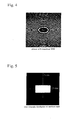
- Fig.5 is an actual intensity distribution of the homogenized beam at the aperture mask.
- White means high beam intensity.
- Black means background without beam.
- Fig.5 is represented by continuously varying tones between white and black.
- the beam is a supergaussian homogenized one without intermediate tones.
- the intensity distribution figure seems to be a binary figure of a white rectangle in a black background.
- the lateral direction is defined to be parallel with x-axis.
- the vertical direction is defined to be parallel with y-axis.
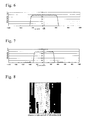
- Fig.6 is an intensity distribution of the homogenized beam in x-direction at the position of the aperture mask.
- the abscissa is measuring positions on x-axis.
- the ordinate is intensity (arbitrary unit) of the beam.
- the x-direction breadth is wide and the beam intensity is nearly constant within a plateau region from -500 ⁇ m to +500 ⁇ m.
- the diffraction rate is 95.92% as aforementioned. Small fluctuation appears in the plateau of ⁇ 500 ⁇ m.
- Fig.6 There are groups of weak noise on x-axis at a left periphery beyond -600 ⁇ m and at a right periphery beyond +600 ⁇ m in Fig.6.
- noise is nearly indiscernible from x-axis.
- the DOE diminishes a 2mm horizontal beam diameter to a 1.2mm side by gathering horizontally extended wave components nearly to ⁇ 0.6 mm edges in x-direction.
- the DOE plays an easy role in x-direction.
- Fig.4 denotes fewer elliptical fringes in x-direction than in y-direction. Diffraction is more moderate in x-direction. This is the reason why noise is weaker at x-axis peripheries.
- Fig.7 is a graph of measured power distribution of the homogenized beam in y-direction (vertical) at the spot of the aperture mask.
- the abscissa of Fig.7 is enlarged by 1.5 times of Fig. 6.
- Y-extending noise (Fig.7) is larger than x-extending noise (Fig.6).
- Fresnel lens when a convex lens is transformed into an identical Fresnel lens.
- the object Fresnel lens consists of many concentric circular isophase fringes with intervals diminishing outward. Individual fringes are slanting annular planes which refract rays by Snell's law and have a refractive function similar to a corresponding part of the original convex lens.
- the Fresnel lens diffracts rays by many isophase concircular fringe edges.
- the Fresnel lens yields diffraction rays and refraction rays.
- a beam output from the Fresnel lens is a sum of diffracted rays and refracted rays.
- An identical DOE can be obtained by replacing a continuous rugged surface of the Fresnel lens by xy-quantized pixels having flat steps. At the conversion from the Fresnel lens to the DOE, all the annular slants disappear and flat pixel steps appear. The refracted rays die out. Configuration of heights and positions of the pixels of the DOE are the first approximation of annular isophase slants of the Fresnel lens. Appearance of flat steps and pixel repetitions incurs higher orders of diffraction. The higher order diffraction which causes noise is a drawback of the DOEs.
- Step thickness (height) distribution is designed for endowing the DOE with the converging function identical to the original convex lens.
- lens/DOE identification is valid only for the first order diffraction rays.
- the 0th order, -1st order, +2nd order diffraction rays are additionally yielded from the DOE.
- the 0th order ones are straight-progressing rays which do not exist in a lens but accompany a DOE which is a set of pixels of flat tops.
- An original lens has no correspondent to the 0th, -1st, +2nd, -2nd, +3rd ...order diffraction.
- a DOE is plagued with unnecessary 0th, -1st or higher order diffraction rays. Straight-progressing 0th-order rays are produced on all the surface of the DOE including peripheries beyond ⁇ 0.6mm.
- the 0th order diffraction is one of the origins of noise.
- the 1st diffraction induces diverging rays which are other origins of the noise.
- the first order diffraction (desired components of diffraction) cannot cancel these sets of noise which are induced by various reasons.
- Noise within peripheries between ⁇ 400 ⁇ m and ⁇ 600 ⁇ m is yielded by the above reasons. Noise appears in y-direction stronger than in x-direction in the example. It is because convergence is stronger in y-direction (2mm ⁇ 0.6mm) than in x-direction (2mm ⁇ 1.2mm).
- Noise-annihilation is an object of placing an aperture mask at the focus of the homogenizer DOE. This is a conspicuous feature of the present invention. However, the role of the aperture mask upon the whole optics is not obvious yet. Thus, all the optical parts are described.
- a homogenized square-sectioned supergaussian beam is branched by the diverging DOE 5 into an arbitrary number of beams with arbitrary directions.
- the divided beam number is assumed to be three. Power fluctuation occurs in any number of separated beams in a similar manner.
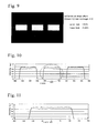
- the diverging DOE has been designed to be repetitions of a unit pattern with phase-change distribution shown in Fig.8.
- a DOE has inherently a thickness-varying pixel distribution for inducting phase-variation of light.
- the thickness variation has sixteen steps for discretely changing the phase of penetrating rays by sixteen steps from 0 degree to 360 degrees. Namely one step corresponds to 22.5 degrees of phase change.
- the DOE pattern in Fig.8 can be considered to be a phase-change pattern as well as a thickness (height)-changing pattern.
- a spacing from a white pixel via grey, black pixels to the next white pixel corresponds to phase-change difference of 360 degrees. Such a rule is common to both the homogenizer DOE and the diverging DOE.
- Fig.8 shows a thickness distribution of a unit pattern (32pixels ⁇ 32pixels) in the diverging DOE.
- a white square at a right lower region is a pixel.
- Grey tone variations correspond to heights of pixels.
- the DOE is built by aligning 25 ⁇ 25 unit patterns in x- and y-directions.
- a wide grey zone lies at a middle. Tiny dots signify the degree of the grey tone which corresponds to phases from 0 degree to 360 degrees.
- the diverging DOE contains a plurality of identical unit-patterns distributing in lengthwise and crosswise directions.
- a unit-pattern has 32 ⁇ 32 pixels. Rays diffracted by the DOE make a dot image having 32 ⁇ 32 periodically distributing dots on an image plane.
- the intensity distribution on the image plane is given by the Fourier transform of pixel height (thickness) distribution of a unit-pattern.
- the intensity distribution can be easily calculated by FFT (Fast Fourier Transform) of pixel heights on a unit pattern on a computer.
- Fig.8 shows an example of a unit-pattern which has 32 ⁇ 32 pixels.
- a diverging DOE is a set of two-dimensionally, periodically aligning identical unit-patterns. Periodicity is an essential character of the diverging DOE (Fig.8).
- Comparison of Fig.4 and Fig.8 clarifies the difference of a non-periodical homogenizing DOE without unit-patterns and a periodical diverging DOE having identical unit-patterns.
- the foregoing homogenizer DOE which has two functions of a homogenizer and a converging lens has a plurality of concentric ellipsoids as shown in Fig.4.
- the homogenizer DOE is a Fresnel type DOE having a definite focal length.
- the diverging DOE which is a Fraunhofer type DOE without converging power has no concentric circles.
- the diverging DOE plays a simple role of making branched identical beams with a definite interval. 360 degrees are enough to a full range of phase differences of rays passing pixels. A single fringe corresponds to 360 degree phase difference. The full range is 360 degrees of phase differences.
- Any diverging DOE has no unique solution but has a variety of solutions.
- a three beams generating DOE has many sets of probable pixel thickness distributions.
- Fig. 8 is an example of a unit-pattern of a three beam generating DOE. There are many other probable unit-patterns which realize three definite-measured identical patterns on an image plane.
- Fig. 9 is three patterns made by the three-diverging beams projected on an image plane.
- the DOE including a set of the identical unit-patterns of Fig. 8 makes three identical rectangular irradiated zones on the image plane.
- Three rectangular white zones align in x-direction with a definite interval.
- a white zone is a 0.2mm ⁇ 0.1mm rectangle.
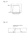
- Fig. 10 shows a result of measurement of diffracted, branched beam intensity distribution along x-axis.
- Three rectangular plateaus with an about 200 ⁇ m length correspond to the three irradiated zones in Fig. 9. Intensity distributions of three plateaus are nearly flat. The intensity ranges from 0.9 to 1. Small fluctuation of the power accompanies three plateaus.
- Fig.11 is a horizontally enlarged graph of the middle plateau of Fig. 10 for showing plateau fluctuation and side noise.
- the irradiated zone in the 0.2mm ⁇ 0.1mm rectangle reveals low-fluctuation, uniform, stable distribution with an upper margin 7.95% and a lower margin -5.30%. This means excellency of the diverging DOE.
- Figs. 9 - 11 show power distribution of diffracted, diverging beams along x-axis. Three plateaus are accompanied by the edges of supergaussian function distribution. [2. Comparison Example 1 (non-mask case; Figs. 12-14)]
- the present invention having such a large-window aperture mask should be compared with a non-mask case omitting an aperture mask and another smaller mask case having an aperture mask with a narrower window which obstructs peripheral portions of a supergaussian beam.
- the non-mask case means a system having only a homogenizer 3, a branching element 5, a lens 6 and an image plane 7 in the system of Fig. 1 or Fig.3, Fig.12 and Fig.13 are a section and a power distribution graph of three branched beams on the image plane in the none aperture mask case.
- Fig.14 is an enlarged power distribution graph of the middle beam on the image plane.
- the non-mask comparison example has a structure similar to Embodiment except non-existence of the aperture mask.
- Fig.12 shows three divided beams projected into three separated rectangles of 0.24mm ⁇ 0.12mm of sides defined by the 1/e 2 attenuation on the image plane.
- Fig.13 which is a power distribution graph, shows three zigzag plateaus. The power fluctuation on the three plateaus is bigger than that in Fig.10 of the present invention.
- the enlarged middle plateau of Fig.14 shows large power dispersion from 0.78 to 1.
- the beam power fluctuation in the uniform region of 0.2mm ⁇ 0.1mm has an upper margin 18.31% and a lower margin -16.03%.
- the big fluctuation signifies incompetence of the maskless system as a homogenizer.
- the present invention employs a wide window aperture mask which does not obstruct a homogenized beam. Namely, the sides 2c and 2d of the aperture mask (2c ⁇ 2d) are larger than the sizes 2a and 2b of the homogenized beam (2a ⁇ 2b). 2c>2a. 2d>2b.
- Comparison Example 2 tried a similar diffraction experiment by making use of another aperture mask with a narrower window which does not satisfy the inequalities (2c> 2a, 2d>2b).
- Comparison Example 2 has a homogenizing optics shown in Fig.1 and Fig.3.
- the window of the aperture mask is 1.0mm ⁇ 0.5mm.
- the window is smaller than the beam section by about 20% in both directions.
- An about 0.05mm - 0.1mm wide peripheral part of the homogenized beam is obstructed by the narrower aperture.
- the use of the smaller aperture mask may be thought to be the best, because the system makes use of only a good-quality inner part of the homogenized beam. But it is not true. Edges including fluctuation are important for establishing good beams projected on the image plane.
- the narrower aperture experiment was done for indicating that the extraction of the inner beam part would induce large fluctuation of the final beams on the
- Fig.16 is a graph of power intensity distribution of three diverging beams of Comparison Example 2. Sharp overshooting surges appear at edges of plateaus of the beam power distribution. The surges are common to six edges of three beam regions.
- the power density in intermediate regions is stable with little fluctuation. But, edge surges raise power fluctuation in Comparison Example 2.
- the fluctuation in the uniform 0.2mm ⁇ 0.1mm regions has a +15.11% margin and -13.04% margin.
- the reason why such large surges appear on the edges is considered as follows.
- the homogenizer DOE generates a 1.2mm ⁇ 0.6mm uniform supergaussian beam from an input Gaussian one.
- the narrower aperture mask deprives the homogenized beam of moderately-varying peripheries which characterize the supergaussian distribution.
- the periphery-annihilation by the narrow aperture causes alleviation of the sizes of the beam irradiated regions in Figs. 15, 16 and 17.
- the edge overshooting surges result from deficiency of cancellation of edge power which should be induced by masked peripheries of the supergaussian function.
- the appearance of overshooting end surges teaches us the importance of the aperture mask having a wide window allowing all the homogenized beam parts to pass.
Landscapes
- Physics & Mathematics (AREA)
- Optics & Photonics (AREA)
- General Physics & Mathematics (AREA)
- Engineering & Computer Science (AREA)
- Health & Medical Sciences (AREA)
- Toxicology (AREA)
- Plasma & Fusion (AREA)
- Mechanical Engineering (AREA)
- Laser Beam Processing (AREA)
- Diffracting Gratings Or Hologram Optical Elements (AREA)
Applications Claiming Priority (2)
| Application Number | Priority Date | Filing Date | Title |
|---|---|---|---|
| JP2003022967A JP3807374B2 (ja) | 2003-01-31 | 2003-01-31 | 一括多点ホモジナイズ光学系 |
| JP2003022967 | 2003-01-31 |
Publications (2)
| Publication Number | Publication Date |
|---|---|
| EP1450199A1 true EP1450199A1 (de) | 2004-08-25 |
| EP1450199B1 EP1450199B1 (de) | 2010-06-09 |
Family
ID=32732878
Family Applications (1)
| Application Number | Title | Priority Date | Filing Date |
|---|---|---|---|
| EP04000008A Expired - Lifetime EP1450199B1 (de) | 2003-01-31 | 2004-01-02 | Optisches Vielpunkthomogenisierungssystem |
Country Status (6)
| Country | Link |
|---|---|
| US (1) | US6909546B2 (de) |
| EP (1) | EP1450199B1 (de) |
| JP (1) | JP3807374B2 (de) |
| KR (1) | KR100935809B1 (de) |
| DE (1) | DE602004027564D1 (de) |
| TW (1) | TWI273288B (de) |
Cited By (5)
| Publication number | Priority date | Publication date | Assignee | Title |
|---|---|---|---|---|
| WO2009090088A1 (de) * | 2008-01-18 | 2009-07-23 | Limo Patentverwaltung Gmbh & Co. Kg | Vorrichtung zur formung eines lichtstrahls sowie verfahren zur herstellung einer derartigen vorrichtung |
| EP1927880A4 (de) * | 2005-09-22 | 2010-10-20 | Sumitomo Electric Industries | Laseroptische vorrichtung |
| DE102013101147A1 (de) | 2013-02-05 | 2014-08-21 | Limo Patentverwaltung Gmbh & Co. Kg | Vorrichtung zur Strahltransformation und Teilung eines Laserstrahls |
| WO2022033995A1 (fr) * | 2020-08-14 | 2022-02-17 | Imagine Optic | Procédés et systèmes pour la génération d'impulsions laser de forte puissance crête |
| DE102024117459A1 (de) * | 2024-06-20 | 2025-12-24 | Jenoptik Optical Systems Gmbh | Optische Anordnung zur Laserprojektion, Vorrichtung zur Laserbearbeitung und Verwendung derselben |
Families Citing this family (43)
| Publication number | Priority date | Publication date | Assignee | Title |
|---|---|---|---|---|
| US6910911B2 (en) | 2002-06-27 | 2005-06-28 | Vocollect, Inc. | Break-away electrical connector |
| US7663122B2 (en) * | 2004-07-14 | 2010-02-16 | Ryugo Hayano | Laser analytical instrument, laser analytical method, and gas leak inspection instrument |
| US7374569B2 (en) * | 2004-09-02 | 2008-05-20 | Dynatronics, Corporation | Dynamically distributing power of a light beam for use in light therapy |
| US7820937B2 (en) * | 2004-10-27 | 2010-10-26 | Boston Scientific Scimed, Inc. | Method of applying one or more electromagnetic beams to form a fusion bond on a workpiece such as a medical device |
| USD558761S1 (en) | 2005-09-19 | 2008-01-01 | Vocollect, Inc. | Portable processing terminal |
| USD549694S1 (en) | 2005-11-15 | 2007-08-28 | Vocollect, Inc. | Headset |
| USD552595S1 (en) | 2005-11-16 | 2007-10-09 | Vocollect, Inc. | Control panel for a headset |
| US8417185B2 (en) | 2005-12-16 | 2013-04-09 | Vocollect, Inc. | Wireless headset and method for robust voice data communication |
| US7885419B2 (en) | 2006-02-06 | 2011-02-08 | Vocollect, Inc. | Headset terminal with speech functionality |
| US7773767B2 (en) * | 2006-02-06 | 2010-08-10 | Vocollect, Inc. | Headset terminal with rear stability strap |
| DE102006007750A1 (de) * | 2006-02-20 | 2007-08-23 | Wavelight Ag | Verfahren und optische Anordnung zur Kontrolle der Fokustiefe eines abbildenden optischen Systems |
| US20070208289A1 (en) * | 2006-03-03 | 2007-09-06 | Jay Walther | Systems and methods for providing light therapy traction |
| US20070208396A1 (en) * | 2006-03-03 | 2007-09-06 | Gary Whatcott | Systems and methods for providing a dynamic light pad |
| US7615722B2 (en) * | 2006-07-17 | 2009-11-10 | Coherent, Inc. | Amorphous silicon crystallization using combined beams from optically pumped semiconductor lasers |
| JP5106130B2 (ja) * | 2008-01-08 | 2012-12-26 | 住友重機械工業株式会社 | レーザビーム照射方法およびレーザビーム照射装置 |
| USD626949S1 (en) | 2008-02-20 | 2010-11-09 | Vocollect Healthcare Systems, Inc. | Body-worn mobile device |
| USD605629S1 (en) | 2008-09-29 | 2009-12-08 | Vocollect, Inc. | Headset |
| US8386261B2 (en) | 2008-11-14 | 2013-02-26 | Vocollect Healthcare Systems, Inc. | Training/coaching system for a voice-enabled work environment |
| US8160287B2 (en) | 2009-05-22 | 2012-04-17 | Vocollect, Inc. | Headset with adjustable headband |
| US8438659B2 (en) | 2009-11-05 | 2013-05-07 | Vocollect, Inc. | Portable computing device and headset interface |
| US8659397B2 (en) | 2010-07-22 | 2014-02-25 | Vocollect, Inc. | Method and system for correctly identifying specific RFID tags |
| USD643400S1 (en) | 2010-08-19 | 2011-08-16 | Vocollect Healthcare Systems, Inc. | Body-worn mobile device |
| USD643013S1 (en) | 2010-08-20 | 2011-08-09 | Vocollect Healthcare Systems, Inc. | Body-worn mobile device |
| CN102375171B (zh) * | 2011-11-09 | 2013-10-02 | 中国科学院物理研究所 | 一种衍射光学元件及其设计方法和在太阳能电池中的应用 |
| KR20140036593A (ko) | 2012-09-17 | 2014-03-26 | 삼성디스플레이 주식회사 | 레이저 가공 장치 |
| KR101414805B1 (ko) * | 2013-04-02 | 2014-07-01 | 주식회사 엘티에스 | 레이저 리프트 오프 공정의 기판 분리장치 |
| JP6193305B2 (ja) * | 2014-07-29 | 2017-09-06 | ウルトラテック インク | 高性能線形成光学システム及び方法 |
| US9910276B2 (en) | 2015-06-30 | 2018-03-06 | Microsoft Technology Licensing, Llc | Diffractive optical elements with graded edges |
| US10670862B2 (en) | 2015-07-02 | 2020-06-02 | Microsoft Technology Licensing, Llc | Diffractive optical elements with asymmetric profiles |
| US10038840B2 (en) | 2015-07-30 | 2018-07-31 | Microsoft Technology Licensing, Llc | Diffractive optical element using crossed grating for pupil expansion |
| US9864208B2 (en) | 2015-07-30 | 2018-01-09 | Microsoft Technology Licensing, Llc | Diffractive optical elements with varying direction for depth modulation |
| US10073278B2 (en) | 2015-08-27 | 2018-09-11 | Microsoft Technology Licensing, Llc | Diffractive optical element using polarization rotation grating for in-coupling |
| US10429645B2 (en) | 2015-10-07 | 2019-10-01 | Microsoft Technology Licensing, Llc | Diffractive optical element with integrated in-coupling, exit pupil expansion, and out-coupling |
| US10241332B2 (en) | 2015-10-08 | 2019-03-26 | Microsoft Technology Licensing, Llc | Reducing stray light transmission in near eye display using resonant grating filter |
| US9946072B2 (en) * | 2015-10-29 | 2018-04-17 | Microsoft Technology Licensing, Llc | Diffractive optical element with uncoupled grating structures |
| US10234686B2 (en) | 2015-11-16 | 2019-03-19 | Microsoft Technology Licensing, Llc | Rainbow removal in near-eye display using polarization-sensitive grating |
| US10108014B2 (en) * | 2017-01-10 | 2018-10-23 | Microsoft Technology Licensing, Llc | Waveguide display with multiple focal depths |
| DE102017217145A1 (de) * | 2017-09-27 | 2019-03-28 | Trumpf Laser Gmbh | Lasersystem und Verfahren zur Erzeugung eines Top-Hat- angenäherten Strahlprofils |
| CN110361797A (zh) * | 2018-03-28 | 2019-10-22 | 福州高意光学有限公司 | 一种改变激光光强分布膜片的制造方法 |
| CN110333563B (zh) * | 2018-03-28 | 2021-11-02 | 福州高意光学有限公司 | 一种光学光阑的制作方法 |
| FR3081737B1 (fr) * | 2018-06-05 | 2022-02-11 | Imagine Optic | Procedes et systemes pour la generation d'impulsions laser de forte puissance crete |
| CN112558312B (zh) * | 2020-12-25 | 2022-09-06 | 湖北工业大学 | 一种高能量利用率高均匀性的光束整形控制方法 |
| CN115407518B (zh) * | 2022-10-31 | 2023-04-25 | 成都莱普科技股份有限公司 | 矩形平顶光斑的发生系统、方法及设备 |
Citations (3)
| Publication number | Priority date | Publication date | Assignee | Title |
|---|---|---|---|---|
| US5835647A (en) * | 1994-08-18 | 1998-11-10 | Aesculap Ag & Co. Kg | Device for generating a laser beam having a homogenized cross section and use of this beam |
| US20020001090A1 (en) * | 2000-06-29 | 2002-01-03 | Leica Microsystems Wetzlar Gmbh. | Illumination device; and coordinate measuring instrument having an illumination device |
| US6433301B1 (en) * | 1999-05-28 | 2002-08-13 | Electro Scientific Industries, Inc. | Beam shaping and projection imaging with solid state UV Gaussian beam to form vias |
Family Cites Families (7)
| Publication number | Priority date | Publication date | Assignee | Title |
|---|---|---|---|---|
| US3476463A (en) | 1965-05-11 | 1969-11-04 | Perkin Elmer Corp | Coherent light optical system yielding an output beam of desired intensity distribution at a desired equiphase surface |
| US5454004A (en) * | 1994-05-06 | 1995-09-26 | Regents Of The University Of Minnesota | Phase grating and mode-selecting mirror for a laser |
| JPH0961610A (ja) | 1994-10-31 | 1997-03-07 | Nippon Steel Corp | バイナリーオプティクス及びそれを用いた集光光学系並びにレーザ加工装置 |
| JPH10153750A (ja) | 1996-11-25 | 1998-06-09 | Sumitomo Electric Ind Ltd | レーザビーム整形光学部品 |
| US6295168B1 (en) * | 1999-12-15 | 2001-09-25 | International Business Machines Corporation | Refractive optical system that converts a laser beam to a collimated flat-top beam |
| JP2001347669A (ja) * | 2000-06-08 | 2001-12-18 | Ricoh Co Ltd | ノズル穴の製造方法およびノズル穴 |
| JP4646278B2 (ja) | 2000-10-26 | 2011-03-09 | 株式会社リコー | 照明光学系及び投射装置 |
-
2003
- 2003-01-31 JP JP2003022967A patent/JP3807374B2/ja not_active Expired - Fee Related
- 2003-11-19 TW TW092132420A patent/TWI273288B/zh not_active IP Right Cessation
- 2003-11-21 KR KR1020030083084A patent/KR100935809B1/ko not_active Expired - Fee Related
- 2003-12-12 US US10/733,284 patent/US6909546B2/en not_active Expired - Lifetime
-
2004
- 2004-01-02 EP EP04000008A patent/EP1450199B1/de not_active Expired - Lifetime
- 2004-01-02 DE DE602004027564T patent/DE602004027564D1/de not_active Expired - Lifetime
Patent Citations (3)
| Publication number | Priority date | Publication date | Assignee | Title |
|---|---|---|---|---|
| US5835647A (en) * | 1994-08-18 | 1998-11-10 | Aesculap Ag & Co. Kg | Device for generating a laser beam having a homogenized cross section and use of this beam |
| US6433301B1 (en) * | 1999-05-28 | 2002-08-13 | Electro Scientific Industries, Inc. | Beam shaping and projection imaging with solid state UV Gaussian beam to form vias |
| US20020001090A1 (en) * | 2000-06-29 | 2002-01-03 | Leica Microsystems Wetzlar Gmbh. | Illumination device; and coordinate measuring instrument having an illumination device |
Cited By (6)
| Publication number | Priority date | Publication date | Assignee | Title |
|---|---|---|---|---|
| EP1927880A4 (de) * | 2005-09-22 | 2010-10-20 | Sumitomo Electric Industries | Laseroptische vorrichtung |
| WO2009090088A1 (de) * | 2008-01-18 | 2009-07-23 | Limo Patentverwaltung Gmbh & Co. Kg | Vorrichtung zur formung eines lichtstrahls sowie verfahren zur herstellung einer derartigen vorrichtung |
| DE102013101147A1 (de) | 2013-02-05 | 2014-08-21 | Limo Patentverwaltung Gmbh & Co. Kg | Vorrichtung zur Strahltransformation und Teilung eines Laserstrahls |
| WO2022033995A1 (fr) * | 2020-08-14 | 2022-02-17 | Imagine Optic | Procédés et systèmes pour la génération d'impulsions laser de forte puissance crête |
| FR3113428A1 (fr) * | 2020-08-14 | 2022-02-18 | Imagine Optic | Procédés et systèmes pour la génération d’impulsions laser de forte puissance crête |
| DE102024117459A1 (de) * | 2024-06-20 | 2025-12-24 | Jenoptik Optical Systems Gmbh | Optische Anordnung zur Laserprojektion, Vorrichtung zur Laserbearbeitung und Verwendung derselben |
Also Published As
| Publication number | Publication date |
|---|---|
| EP1450199B1 (de) | 2010-06-09 |
| JP3807374B2 (ja) | 2006-08-09 |
| DE602004027564D1 (de) | 2010-07-22 |
| US20040150887A1 (en) | 2004-08-05 |
| US6909546B2 (en) | 2005-06-21 |
| JP2004230432A (ja) | 2004-08-19 |
| TW200419200A (en) | 2004-10-01 |
| KR100935809B1 (ko) | 2010-01-08 |
| TWI273288B (en) | 2007-02-11 |
| KR20040069951A (ko) | 2004-08-06 |
Similar Documents
| Publication | Publication Date | Title |
|---|---|---|
| EP1450199B1 (de) | Optisches Vielpunkthomogenisierungssystem | |
| Soifer et al. | Iteractive methods for diffractive optical elements computation | |
| US6654183B2 (en) | System for converting optical beams to collimated flat-top beams | |
| US10642059B2 (en) | Optical field transformation methods and systems | |
| JP7412357B2 (ja) | 光学的配置とレーザシステム | |
| EP1574892A2 (de) | Optisches System zur Homogenisierung von Lichtstrahlen, mit einem diffraktiven optischen Element | |
| US6567226B2 (en) | Method for designing a refractive or reflective optical system and method for designing a diffraction optical element | |
| US20110043917A1 (en) | Diffractive laser beam homogenizer including a photo-active material and method of fabricating the same | |
| KR20080021090A (ko) | 웨지를 이용한 회절형 빔 호모지나이저 광학계 | |
| US7193791B2 (en) | Tilt error reducing aspherical single lens homogenizer | |
| JP3969197B2 (ja) | レーザ照射装置 | |
| KR20120039747A (ko) | 기판 처리를 위해 광 빔을 생성하는 광학 시스템 | |
| CN116931283A (zh) | 一种具有激光防护功能的光电成像系统 | |
| JP6743372B2 (ja) | 光広角照射装置 | |
| US20220137271A1 (en) | Optical element having a randomizing digital lens array and/or a diffuser function | |
| Danziger et al. | Multilevel diffractive elements for generalized wavefront shaping | |
| CN118550019B (zh) | 一种基于等面积随机网格的自由曲面微透镜阵列扩散片 | |
| JP7662040B2 (ja) | 回折素子の設計方法および回折素子の製造方法 | |
| US9042032B2 (en) | Optical arrangement for converting an incident light beam, method for converting a light beam to a line focus, and optical device therefor | |
| CN119596563A (zh) | 光束变换装置及光学加工设备 | |
| JP2009058625A (ja) | レーザー照射光学系 |
Legal Events
| Date | Code | Title | Description |
|---|---|---|---|
| PUAI | Public reference made under article 153(3) epc to a published international application that has entered the european phase |
Free format text: ORIGINAL CODE: 0009012 |
|
| AK | Designated contracting states |
Kind code of ref document: A1 Designated state(s): AT BE BG CH CY CZ DE DK EE ES FI FR GB GR HU IE IT LI LU MC NL PT RO SE SI SK TR |
|
| AX | Request for extension of the european patent |
Extension state: AL LT LV MK |
|
| RIN1 | Information on inventor provided before grant (corrected) |
Inventor name: THE INVENTOR HAS AGREED TO WAIVE HIS ENTITLEMENT T |
|
| 17P | Request for examination filed |
Effective date: 20040930 |
|
| AKX | Designation fees paid |
Designated state(s): DE |
|
| RBV | Designated contracting states (corrected) |
Designated state(s): DE |
|
| RIN1 | Information on inventor provided before grant (corrected) |
Inventor name: HIRAI, TAKAYUKI, OSAKA WORKS OF |
|
| GRAP | Despatch of communication of intention to grant a patent |
Free format text: ORIGINAL CODE: EPIDOSNIGR1 |
|
| GRAS | Grant fee paid |
Free format text: ORIGINAL CODE: EPIDOSNIGR3 |
|
| GRAA | (expected) grant |
Free format text: ORIGINAL CODE: 0009210 |
|
| AK | Designated contracting states |
Kind code of ref document: B1 Designated state(s): DE |
|
| REF | Corresponds to: |
Ref document number: 602004027564 Country of ref document: DE Date of ref document: 20100722 Kind code of ref document: P |
|
| PLBE | No opposition filed within time limit |
Free format text: ORIGINAL CODE: 0009261 |
|
| STAA | Information on the status of an ep patent application or granted ep patent |
Free format text: STATUS: NO OPPOSITION FILED WITHIN TIME LIMIT |
|
| 26N | No opposition filed |
Effective date: 20110310 |
|
| REG | Reference to a national code |
Ref country code: DE Ref legal event code: R097 Ref document number: 602004027564 Country of ref document: DE Effective date: 20110309 |
|
| PGFP | Annual fee paid to national office [announced via postgrant information from national office to epo] |
Ref country code: DE Payment date: 20201222 Year of fee payment: 18 |
|
| REG | Reference to a national code |
Ref country code: DE Ref legal event code: R119 Ref document number: 602004027564 Country of ref document: DE |
|
| PG25 | Lapsed in a contracting state [announced via postgrant information from national office to epo] |
Ref country code: DE Free format text: LAPSE BECAUSE OF NON-PAYMENT OF DUE FEES Effective date: 20220802 |