EP1448856B1 - Einziehbare strassensperre - Google Patents
Einziehbare strassensperre Download PDFInfo
- Publication number
- EP1448856B1 EP1448856B1 EP02803887A EP02803887A EP1448856B1 EP 1448856 B1 EP1448856 B1 EP 1448856B1 EP 02803887 A EP02803887 A EP 02803887A EP 02803887 A EP02803887 A EP 02803887A EP 1448856 B1 EP1448856 B1 EP 1448856B1
- Authority
- EP
- European Patent Office
- Prior art keywords
- barrier
- elements
- barrier element
- supporting
- road surface
- Prior art date
- Legal status (The legal status is an assumption and is not a legal conclusion. Google has not performed a legal analysis and makes no representation as to the accuracy of the status listed.)
- Expired - Lifetime
Links
Images



Classifications
-
- E—FIXED CONSTRUCTIONS
- E01—CONSTRUCTION OF ROADS, RAILWAYS, OR BRIDGES
- E01F—ADDITIONAL WORK, SUCH AS EQUIPPING ROADS OR THE CONSTRUCTION OF PLATFORMS, HELICOPTER LANDING STAGES, SIGNS, SNOW FENCES, OR THE LIKE
- E01F15/00—Safety arrangements for slowing, redirecting or stopping errant vehicles, e.g. guard posts or bollards; Arrangements for reducing damage to roadside structures due to vehicular impact
- E01F15/02—Continuous barriers extending along roads or between traffic lanes
- E01F15/12—Continuous barriers extending along roads or between traffic lanes and having means for providing occasional passage, e.g. for emergency vehicles
Definitions
- the present invention relates to safety barriers for road use of the type comprising at least one barrier element and a supporting structure for supporting the barrier element, provided with means for anchoring thereof to the ground, wherein said supporting structure is movable between a first position, in which the barrier element is in an operative position above the road surface, and a second position, in which the barrier element is in an inoperative position in which it does not substantially project above the road surface, wherein in said inoperative condition the barrier element is received inside a trench formed in the road surface, wherein the supporting structure includes at least one supporting column articulated at one of its ends to a bracket for anchorage to the ground and, at the opposite end, to the barrier element, said supporting column being pivotable between an operative upright position and an inoperative lowered position, and in which means are provided for controlling rotation of said supporting column.
- a road barrier of the above indicated type is disclosed in document DE-A-34 20 503 .
- more barrier elements are provided which, when in the lowered position, are spaced apart from each other, so that free spaces are defined therebetween which require the provision of additional platforms in order to cover the trench which receives the barrier elements in the lowered condition.
- interruptions are formed at the areas interposed between each lowered element and an adjacent raised element.
- this solution shows a barrier with a connecting element which connects a retractable barrier element to a non-retractable barrier element, it does not provide for a connecting element between two barrier elements which are both retractable, so that there are not ample possibilities to choose the barrier portion which one wishes to retract.
- the barrier of this second known solution does not ensure a continuous surface both above and on the two sides of the barrier and moreover it has columns for supporting the retractable element which are directly articulated to the walls of the trench in which the retracted element is received, so that any operations for replacing a damaged barrier element are lengthy and costly.
- the object of the present invention is that of providing a road barrier which is able to overcome all the above mentioned drawbacks.
- the invention provides a road barrier having all the features which have been indicated at the beginning of the present description and further characterized in that said safety barrier comprises a succession of sets of one or more barrier elements, the barrier elements of each set being rigidly connected to each other, and adjacent sets of barrier elements being connected to each other by means of articulated connecting elements having variable length, which enable a relative displacement in a vertical direction of any set with respect to the other, while always defining a continuous upper surface and two side continuous side surfaces of the barrier in any position of any set of barrier elements of the barrier.
- each set of barrier elements is constituted by barrier elements whose supporting columns are articulated to a bracket which is anchored to the ground, each of these sets forms a unit which can be easily removed and replaced.
- a further object of the present invention is that of ensuring that the barrier elements can be all moved to their lowered position even in case of an absence of the electric main supply, which condition may well take place in case of an accident, or in case of a fire inside the tunnel.
- the barrier according to the invention is further characterized in that a solenoid valve is provided which can be activated in order to put a cylinder for raising the barrier element in a discharge condition, in order to cause lowering of the respective barrier element, and in that emergency electric supply means are provided for activating said solenoid valve in case of a failure in the main supply of electric current.
- a solenoid valve is provided which can be activated in order to put a cylinder for raising the barrier element in a discharge condition, in order to cause lowering of the respective barrier element
- emergency electric supply means are provided for activating said solenoid valve in case of a failure in the main supply of electric current.
- the reference number 1 designates as a whole a road tunnel having two lanes 2, 3 for passage of traffic in two opposite directions, which are separated by a safety barrier 4 built according to the invention.
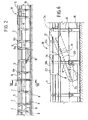
- the barrier 4 comprises an aligned succession of barrier elements 5 consisting of metal channel section with reversed-U cross section and undulations for stiffening, if so required, the said barrier elements being each carried by a set of three supporting columns 6.
- Each column 6 has one end articulated in 7 ( Figure 2) to the respective barrier element 5, and the opposite end articulated in 8 to an attachment element anchored to the ground.
- the barrier elements 5 are rigidly connected together in sets of a number of elements (for example, three) by connecting elements 9 consisting of reversed-U channel section, which are set on top of one other and are bolted by means of screws 9a (see Figure 7) to the barrier elements 5.
- the ensemble consisting of three barrier elements 5 making up each set can be displaced between its normal operating position, in which it projects above the road surface ( Figure 2), and a lowered, inoperative, position, which is reached by means of simultaneous rotation downwards of the columns 6 about their respective bottom articulations 8 and in which the barrier elements 5 disappear inside a trench 10 made in the read surface.
- the movement of the barrier elements 5 between an inoperative position and the operative position is controlled, for each set of three barrier elements 5 connected rigidly together by the connecting elements 9, by a single hydraulic cylinder 11 having one end articulated to the ground and the opposite end articulated to a bracket 12 ( Figure 3) of the central column 6 of the set of three columns 6 associated to the central barrier element 5 of the set of three barrier elements 5 rigidly connected together.
- the said central column 6 is provided with a bracing arm 13.
- a plate 40 is set between each pair of adjacent columns 6 (only one plate 40 being illustrated), which has both a stiffening function and the function of partially closing the trench 10 when the barrier is raised.
- the hydraulic cylinder 11 is supplied by a pump 14 which is controlled by an electric motor 15, the assembly consisting of the motor 15 and the pump 14 being mounted inside a channel 16 ( Figure 3) anchored to the ground. Fixed to the said channel are also the attachments 17 which are provided in the trench 10 (see also Figure 7). In this way, the entire module consisting of the channel 16 and all the components illustrated in Figure 3 can be readily and quickly replaced.
- the system is provided with means for automatic control of lowering of the barrier in the event of failure of electric power supply (as in the case of an accident in a tunnel).
- a 12-V emergency electric power generator may be envisaged which drives a solenoid valve that controls the cylinder.
- Figure 4 is a perspective view which clearly illustrates the connecting element 9 that rigidly joins barrier elements 5 to form a set of three elements.
- Figure 5 is a perspective view illustrating a connecting structure 18 which is set between two adjacent sets of three barrier elements 5.
- the structure 18 comprises two portions of channel section 18a, 18b which are articulated in 7a, 7b to two adjacent columns 6 (see Figure 6) and which are moreover connected together in an articulated way by means of transverse pins 7c.
- the articulation in 7b is obtained by engagement of the side pins in side slits 20 made in the sides of the respective barrier element 5.
- the articulation 7c is also obtained by means of side pins which engage both the slits 20 made in the element 18a and the slits 21 made in the element 18b.
- the fluid cylinder is of the single effect type, which causes raising of the respective barrier element when it is supplied with fluid under pressure, whereas it automatically returns to the condition corresponding to the lowering of the barrier element when its hydraulic chamber is connected to discharge.
- this chamber of the fluid cylinder can be connected to a discharge by means of a solenoid valve which can be activated by an emergency electric supply (such as a backup battery, or an emergency electric generator) in case the main supply is interrupted following an emergency situation such as in case of a fire within the tunnel.
- an emergency electric supply such as a backup battery, or an emergency electric generator
- the elements of the barrier can also be used to carry an optical guide.
- a duct made of transparent plastic material such as polycarbon
- a light source at one end for example constituted by a plurality of LED devices
- a closing cover at the opposite end with a reflective film for example constituted by a plurality of LED devices
- the LED light source is supplied with a low voltage direct current and offers a high degree of safety in the system as well as a low energy consumption.
- this optical guide enables the forwarding of coloured light signals, if necessary intermittent, which are controlled by an electronic control unit and have the purpose for instance of signalling the proper safety spacing between each vehicle and the subsequent one, the safety speed and the stop areas for the vehicles which travel through the tunnel.
- the idea underlying the invention is to provide a safety barrier that can be quickly brought into an inoperative condition in which it does not project above the road surface, with the consequent advantages that have been mentioned at the beginning of the present description.
- the structure and arrangement of the barrier elements that have been illustrated herein, by way of example could be altogether different.
- a further preferred characteristic of the invention lies in the characteristic described previously, which regards the possibility of displacing only one portion of the barrier between the operative position and the inoperative position, without changing the positions of the adjacent portions.
- each lowerable barrier unit comprises a single barrier element.
Landscapes
- Engineering & Computer Science (AREA)
- Architecture (AREA)
- Civil Engineering (AREA)
- Structural Engineering (AREA)
- Refuge Islands, Traffic Blockers, Or Guard Fence (AREA)
- Vehicle Step Arrangements And Article Storage (AREA)
- Closing And Opening Devices For Wings, And Checks For Wings (AREA)
- Lock And Its Accessories (AREA)
- Switches With Compound Operations (AREA)
- Vehicle Body Suspensions (AREA)
- Road Signs Or Road Markings (AREA)
Claims (5)
- Sicherheitsbarriere (4) zur Verwendung in Straßen, umfassend:- zumindest ein Barriereelement (5) und- eine Unterstützungsstruktur (6) zum Unterstützen des Barriereelements, ausgestattet mit Mitteln, um diese im Boden (8) zu verankern,- wobei die Unterstützungsstruktur versetzbar ist zwischen einer ersten Position, in welcher das Barriereelement (5) in einem Betriebszustand über (9) der Straßenoberfläche (3) ist, und einer zweiten Position, in welcher das Barriereelement in einem inoperativen Zustand ist, in welchem es nicht wesentlich über die Straßenoberfläche hinausragt,- wobei in dem inoperativen Zustand das Barriereelement (5) innerhalb eines Grabens (10) enthalten ist, der in der Straßenoberfläche gebildet ist,- wobei die unterstützende Struktur einschließt zumindest eine unterstützende Säule (6), an einem ihrer Enden beweglich an eine Halterung (17) gekoppelt, zum Verankern am Boden und an der anderen Seite an das Barriereelement (5); die unterstützende Säule (6) ist drehbar zwischen einer aufrechten operativen Position und einer niedrigeren inoperativen Position,- wobei Mittel vorgesehen sind (11) zum Steuern einer Drehung der unterstützenden Säule (6),dadurch gekennzeichnet, dass die Sicherheitsbarriere umfasst eine Abfolge von Sätzen einer oder mehrerer Barriereelemente (5), die Elemente jedes Satzes sind starr miteinander (9) verbunden, und benachbarte Sätze sind miteinander verbunden mittels beweglich gekoppelter Verbindungselemente, die eine variable Länge (18) haben, welche eine relative Versetzung in der vertikalen Richtung eines Satzes relativ zu dem anderen ermöglicht, wobei immer eine kontinuierliche obere Oberfläche und zwei kontinuierliche Seitenoberflächen definiert werden für die Barriere in jeder Position von jedem Satz der Barriere.
- Barriere nach Anspruch 1, dadurch gekennzeichnet, dass das Barriereelement (5) und die beweglich gekoppelten Verbindungselemente (18) als Metallprofile mit einem Querschnitt in Form eines umgekehrten U vorliegen, wobei jedes eine obere Wand und zwei Seitenwände hat, die sich durch einen wesentlichen Abschnitt der Höhe der unterstützenden Säulen erstrecken.
- Barriere nach Anspruch 1, dadurch gekennzeichnet, dass die Mittel zum Steuern einer Rotation der unterstützenden Säule einschließen einen Fluidzylinder, ein Magnetventil zum Verbinden des Fluidzylinders zum Entladen, um ein Absenken des jeweiligen Barriereelements in seine eingezogene Position herbeizuführen, und elektrische Notfallversorgungsmittel zum Aktivieren des Magnetventils im Fall einer Unterbrechung der elektrischen Hauptversorgung.
- Barriere nach Anspruch 3, dadurch gekennzeichnet, dass die Mittel zum Aktivieren des Magnetventils in der Lage sind, automatisch in Betrieb zu gehen im Fall einer Unterbrechung der elektrischen Hauptversorgung.
- Barriere nach einem der vorangegangenen Ansprüche, dadurch gekennzeichnet, dass eine optische Führung mit einem oder mehreren Elementen der Barriere verbunden ist.
Applications Claiming Priority (3)
| Application Number | Priority Date | Filing Date | Title |
|---|---|---|---|
| IT2001TO001105A ITTO20011105A1 (it) | 2001-11-27 | 2001-11-27 | ,,barriera stradale a scomparsa,,. |
| ITTO20011105 | 2001-11-27 | ||
| PCT/IB2002/004834 WO2003046289A1 (en) | 2001-11-27 | 2002-11-19 | Retractable road barrier |
Publications (2)
| Publication Number | Publication Date |
|---|---|
| EP1448856A1 EP1448856A1 (de) | 2004-08-25 |
| EP1448856B1 true EP1448856B1 (de) | 2007-08-22 |
Family
ID=11459312
Family Applications (1)
| Application Number | Title | Priority Date | Filing Date |
|---|---|---|---|
| EP02803887A Expired - Lifetime EP1448856B1 (de) | 2001-11-27 | 2002-11-19 | Einziehbare strassensperre |
Country Status (7)
| Country | Link |
|---|---|
| US (1) | US6926462B1 (de) |
| EP (1) | EP1448856B1 (de) |
| AT (1) | ATE371058T1 (de) |
| AU (1) | AU2002365492A1 (de) |
| DE (1) | DE60222009T2 (de) |
| IT (1) | ITTO20011105A1 (de) |
| WO (1) | WO2003046289A1 (de) |
Cited By (2)
| Publication number | Priority date | Publication date | Assignee | Title |
|---|---|---|---|---|
| US20230121725A1 (en) * | 2021-10-14 | 2023-04-20 | Vandorf PAT1 Inc. | Pedestrian Access Terminal |
| US12084819B2 (en) | 2021-07-15 | 2024-09-10 | Three Smith Group Limited | Barrier member |
Families Citing this family (25)
| Publication number | Priority date | Publication date | Assignee | Title |
|---|---|---|---|---|
| CH696002A5 (de) * | 2001-12-21 | 2006-11-15 | Aquarius R S Wegerer Versicher | Fahrbahnbegrenzung. |
| GB0218347D0 (en) * | 2002-08-08 | 2002-09-18 | Primac Ltd | Retractable barrier system |
| DE10256199B4 (de) * | 2002-12-02 | 2004-11-18 | Linde, Albrecht von, Dr. | Vorrichtung und Verfahren zur Veränderung der Streckenführung einer Fahrzeugrennstrecke |
| US7037028B1 (en) * | 2003-05-01 | 2006-05-02 | Intertex Barriers & Booths, Inc. | Security barrier |
| WO2005028757A1 (en) * | 2003-09-22 | 2005-03-31 | Armorflex Limited | Guardrail |
| DE602004015145D1 (de) * | 2003-11-06 | 2008-08-28 | Tallwang Holdings Pty Ltd | Sperrschrankensystem für Fahrzeuge |
| GB2422397A (en) * | 2004-12-04 | 2006-07-26 | David Richard Hendrik Veen | Quick release removable crash barrier |
| NZ546970A (en) | 2006-05-04 | 2009-01-31 | Armorflex Ltd | Improvements in and relating to cable-barriers |
| US8496395B2 (en) * | 2006-05-10 | 2013-07-30 | Gary D. Miracle | Vertically actuated vehicle barrier system |
| JP2010501742A (ja) * | 2006-08-18 | 2010-01-21 | ナム パク,シン | 太陽光を利用した安全灯が付加された道路の中央分離帯の遮光幕 |
| US8596617B2 (en) | 2006-11-06 | 2013-12-03 | Axip Limited | Impact energy dissipation system |
| NZ555598A (en) * | 2007-06-01 | 2010-02-26 | Armorflex Ltd | Improved Barrier Section Connection System |
| NZ556782A (en) * | 2007-07-27 | 2010-03-26 | Armorflex Ltd | Method of producing a frangible post |
| DE102008018113A1 (de) * | 2008-04-09 | 2009-10-22 | Heintzmann Sicherheitssysteme Gmbh & Co. Kg | Fahrzeugrückhaltesystem |
| US8424849B2 (en) * | 2008-06-04 | 2013-04-23 | Axip Limited | Guardrail |
| US20100308294A1 (en) * | 2009-06-04 | 2010-12-09 | William Orville Watkins | Open and close railgate |
| EP2418324B1 (de) | 2010-07-22 | 2012-12-26 | Jörg P. Junker | Leitplankenanordnung |
| NZ590876A (en) * | 2011-12-23 | 2012-09-28 | Axip Ltd | A coupling arrangment for guardrails which upon telescopic slinding of the rails causes an increasing clamping force between them |
| AU2015343512B2 (en) * | 2014-11-06 | 2020-04-16 | The Texas A&M University System | Single anchor terminal |
| US9517778B2 (en) | 2015-03-27 | 2016-12-13 | Kenneth I. Thompson | Railway passenger gate assembly |
| KR20190105022A (ko) * | 2016-12-26 | 2019-09-11 | 사란시 굽타 | 비상 차량용 전용 차로 생성 장치 |
| JP6494120B2 (ja) * | 2017-01-30 | 2019-04-03 | 大都技研株式会社 | 起伏収容式仮設防護柵 |
| DE102018203483A1 (de) | 2018-03-08 | 2019-09-12 | Bayerische Motoren Werke Aktiengesellschaft | Verfahren zum Bilden einer Straßensperre mittels Fahrzeugen |
| CN110689739B (zh) * | 2019-10-12 | 2021-12-28 | 辽宁省城乡建设规划设计院有限责任公司 | 一种海绵城市建设道路指示装置 |
| IT202200000578A1 (it) | 2022-01-17 | 2023-07-17 | Pasquale Impero | Barriera di sicurezza stradale e infrastruttura |
Family Cites Families (13)
| Publication number | Priority date | Publication date | Assignee | Title |
|---|---|---|---|---|
| US3807699A (en) * | 1973-01-19 | 1974-04-30 | W France | Safety guard rail for highway medians |
| US4332503A (en) * | 1977-06-10 | 1982-06-01 | Hurst Jr George H | Apparatus for signaling direction of travel on a road bed |
| US4490068A (en) * | 1983-04-25 | 1984-12-25 | Dickinson Harry D | Hydraulic safety barrier traffic-way controller |
| CH660896A5 (de) * | 1983-06-13 | 1987-05-29 | Burri Ag | Fahrbahn-abschrankungsstrecke. |
| US4916859A (en) * | 1985-07-02 | 1990-04-17 | Embassy Gate Associates, L.P. | Assault-resistant gate |
| FR2606049B1 (fr) * | 1986-11-04 | 1993-03-12 | Mothe Gerard | Barriere anti-intrusion modulaire |
| NO178003C (no) * | 1990-01-18 | 1996-01-03 | Roads Corp | Flyttbar barriere |
| US5009542A (en) * | 1990-03-06 | 1991-04-23 | Hardin Jr Paul W | Traffic barrier gate |
| US5263281A (en) * | 1992-10-08 | 1993-11-23 | Sun Power Security Gates Inc. | Vertically pivotal security gate |
| US5464177A (en) * | 1993-12-29 | 1995-11-07 | The B.F. Goodrich Company | Energy absorbing impact barrier |
| US5498100A (en) * | 1994-10-07 | 1996-03-12 | Guernsey; Robert M. | Retractable delineator system for suspension span & truss bridges |
| US5551796A (en) * | 1995-01-20 | 1996-09-03 | Emergency Public Safety Services, L.L.C. | Moveable barrier |
| FR2750148B1 (fr) * | 1996-06-20 | 1998-09-11 | Amenagement Routier Comp Franc | Dispositif permettant de creer une ouverture dans une file de dispositifs de retenue |
-
2001
- 2001-11-27 IT IT2001TO001105A patent/ITTO20011105A1/it unknown
-
2002
- 2002-11-19 AT AT02803887T patent/ATE371058T1/de not_active IP Right Cessation
- 2002-11-19 WO PCT/IB2002/004834 patent/WO2003046289A1/en not_active Ceased
- 2002-11-19 DE DE60222009T patent/DE60222009T2/de not_active Expired - Lifetime
- 2002-11-19 EP EP02803887A patent/EP1448856B1/de not_active Expired - Lifetime
- 2002-11-19 US US10/470,311 patent/US6926462B1/en not_active Expired - Fee Related
- 2002-11-19 AU AU2002365492A patent/AU2002365492A1/en not_active Abandoned
Non-Patent Citations (1)
| Title |
|---|
| None * |
Cited By (3)
| Publication number | Priority date | Publication date | Assignee | Title |
|---|---|---|---|---|
| US12084819B2 (en) | 2021-07-15 | 2024-09-10 | Three Smith Group Limited | Barrier member |
| US20230121725A1 (en) * | 2021-10-14 | 2023-04-20 | Vandorf PAT1 Inc. | Pedestrian Access Terminal |
| US12571258B2 (en) * | 2021-10-14 | 2026-03-10 | Rsg International Corp. | Pedestrian access terminal |
Also Published As
| Publication number | Publication date |
|---|---|
| ATE371058T1 (de) | 2007-09-15 |
| EP1448856A1 (de) | 2004-08-25 |
| US20050175408A1 (en) | 2005-08-11 |
| AU2002365492A1 (en) | 2003-06-10 |
| DE60222009D1 (de) | 2007-10-04 |
| DE60222009T2 (de) | 2008-05-15 |
| WO2003046289A1 (en) | 2003-06-05 |
| US6926462B1 (en) | 2005-08-09 |
| ITTO20011105A1 (it) | 2003-05-27 |
Similar Documents
| Publication | Publication Date | Title |
|---|---|---|
| US6926462B1 (en) | Retractable road barrier | |
| US20190301117A1 (en) | Movable crash barrier section | |
| US20200208363A1 (en) | Safety trailer | |
| EP0445995A1 (de) | Schranke für Begrenzungsbarriere | |
| EP3655588B1 (de) | Vorrichtung mit elektrischer oder pneumatischer betätigung eines klappmechanismus zur anregung zur verringerung der fahrzeuggeschwindigkeit | |
| CA2768048C (en) | Self-supporting pier for a retractable roof system for a large building structure | |
| US4690583A (en) | Flat folding alternating barrier | |
| EP1995381B1 (de) | Eingebautes Geschwindigkeitsverringerungssystem für Straßenverkehr | |
| EA029739B1 (ru) | Пересечение рельсовых путей, предусмотренное для пересечения направляющего рельса со вторым рельсом | |
| WO2010091449A1 (en) | A ladder deployment system | |
| EP0507624B1 (de) | Anlage zum Durchfahrtkontrolle von Fahrzeugen | |
| KR102756085B1 (ko) | 침수 방지장치와 침수 대피구조를 구비한 지하차도 구조체 | |
| JPH07292622A (ja) | 標 識 | |
| CN113998616B (zh) | 基于举升车的架棚钢梁安装方法 | |
| KR101016917B1 (ko) | 도로의 안전 및 조명 시스템 | |
| KR20210030128A (ko) | 도로교통 표시장치 | |
| CN212641304U (zh) | 一种交通车辆分流的路基路面结构 | |
| KR102803336B1 (ko) | 진출입 자동차단기 | |
| WO2006058383A1 (en) | Structural barrier system | |
| ES2329192T3 (es) | Dispositivo para el entrenamiento de conductores. | |
| CN216640372U (zh) | 一种具有多功能顶盖舱的柱式阻车路障 | |
| KR102964627B1 (ko) | 터널, 교량 및 지하차도 진입차단을 위한 회차기능을 갖는 승강식 진입차단장치 | |
| CN219080157U (zh) | 一种用于道路的绿色建材路墩 | |
| EP4223933A1 (de) | Strassenabsperrungselement | |
| KR100632275B1 (ko) | 노면 접속장치 |
Legal Events
| Date | Code | Title | Description |
|---|---|---|---|
| PUAI | Public reference made under article 153(3) epc to a published international application that has entered the european phase |
Free format text: ORIGINAL CODE: 0009012 |
|
| 17P | Request for examination filed |
Effective date: 20030711 |
|
| AK | Designated contracting states |
Kind code of ref document: A1 Designated state(s): AT BE BG CH CY CZ DE DK EE ES FI FR GB GR IE IT LI LU MC NL PT SE SK TR |
|
| AX | Request for extension of the european patent |
Extension state: AL LT LV MK RO SI |
|
| GRAP | Despatch of communication of intention to grant a patent |
Free format text: ORIGINAL CODE: EPIDOSNIGR1 |
|
| GRAS | Grant fee paid |
Free format text: ORIGINAL CODE: EPIDOSNIGR3 |
|
| GRAA | (expected) grant |
Free format text: ORIGINAL CODE: 0009210 |
|
| AK | Designated contracting states |
Kind code of ref document: B1 Designated state(s): AT BE BG CH CY CZ DE DK EE ES FI FR GB GR IE IT LI LU MC NL PT SE SK TR |
|
| REG | Reference to a national code |
Ref country code: GB Ref legal event code: FG4D |
|
| REG | Reference to a national code |
Ref country code: CH Ref legal event code: EP |
|
| REG | Reference to a national code |
Ref country code: IE Ref legal event code: FG4D |
|
| REF | Corresponds to: |
Ref document number: 60222009 Country of ref document: DE Date of ref document: 20071004 Kind code of ref document: P |
|
| PG25 | Lapsed in a contracting state [announced via postgrant information from national office to epo] |
Ref country code: NL Free format text: LAPSE BECAUSE OF FAILURE TO SUBMIT A TRANSLATION OF THE DESCRIPTION OR TO PAY THE FEE WITHIN THE PRESCRIBED TIME-LIMIT Effective date: 20070822 Ref country code: ES Free format text: LAPSE BECAUSE OF FAILURE TO SUBMIT A TRANSLATION OF THE DESCRIPTION OR TO PAY THE FEE WITHIN THE PRESCRIBED TIME-LIMIT Effective date: 20071203 Ref country code: FI Free format text: LAPSE BECAUSE OF FAILURE TO SUBMIT A TRANSLATION OF THE DESCRIPTION OR TO PAY THE FEE WITHIN THE PRESCRIBED TIME-LIMIT Effective date: 20070822 Ref country code: BG Free format text: LAPSE BECAUSE OF FAILURE TO SUBMIT A TRANSLATION OF THE DESCRIPTION OR TO PAY THE FEE WITHIN THE PRESCRIBED TIME-LIMIT Effective date: 20071122 |
|
| NLV1 | Nl: lapsed or annulled due to failure to fulfill the requirements of art. 29p and 29m of the patents act | ||
| PG25 | Lapsed in a contracting state [announced via postgrant information from national office to epo] |
Ref country code: LI Free format text: LAPSE BECAUSE OF FAILURE TO SUBMIT A TRANSLATION OF THE DESCRIPTION OR TO PAY THE FEE WITHIN THE PRESCRIBED TIME-LIMIT Effective date: 20070822 Ref country code: CH Free format text: LAPSE BECAUSE OF FAILURE TO SUBMIT A TRANSLATION OF THE DESCRIPTION OR TO PAY THE FEE WITHIN THE PRESCRIBED TIME-LIMIT Effective date: 20070822 Ref country code: AT Free format text: LAPSE BECAUSE OF FAILURE TO SUBMIT A TRANSLATION OF THE DESCRIPTION OR TO PAY THE FEE WITHIN THE PRESCRIBED TIME-LIMIT Effective date: 20070822 |
|
| REG | Reference to a national code |
Ref country code: CH Ref legal event code: PL |
|
| PG25 | Lapsed in a contracting state [announced via postgrant information from national office to epo] |
Ref country code: BE Free format text: LAPSE BECAUSE OF FAILURE TO SUBMIT A TRANSLATION OF THE DESCRIPTION OR TO PAY THE FEE WITHIN THE PRESCRIBED TIME-LIMIT Effective date: 20070822 |
|
| REG | Reference to a national code |
Ref country code: IE Ref legal event code: FD4D |
|
| ET | Fr: translation filed | ||
| PG25 | Lapsed in a contracting state [announced via postgrant information from national office to epo] |
Ref country code: GR Free format text: LAPSE BECAUSE OF FAILURE TO SUBMIT A TRANSLATION OF THE DESCRIPTION OR TO PAY THE FEE WITHIN THE PRESCRIBED TIME-LIMIT Effective date: 20071123 Ref country code: DK Free format text: LAPSE BECAUSE OF FAILURE TO SUBMIT A TRANSLATION OF THE DESCRIPTION OR TO PAY THE FEE WITHIN THE PRESCRIBED TIME-LIMIT Effective date: 20070822 |
|
| PG25 | Lapsed in a contracting state [announced via postgrant information from national office to epo] |
Ref country code: SK Free format text: LAPSE BECAUSE OF FAILURE TO SUBMIT A TRANSLATION OF THE DESCRIPTION OR TO PAY THE FEE WITHIN THE PRESCRIBED TIME-LIMIT Effective date: 20070822 Ref country code: PT Free format text: LAPSE BECAUSE OF FAILURE TO SUBMIT A TRANSLATION OF THE DESCRIPTION OR TO PAY THE FEE WITHIN THE PRESCRIBED TIME-LIMIT Effective date: 20080122 Ref country code: IE Free format text: LAPSE BECAUSE OF FAILURE TO SUBMIT A TRANSLATION OF THE DESCRIPTION OR TO PAY THE FEE WITHIN THE PRESCRIBED TIME-LIMIT Effective date: 20070822 Ref country code: CZ Free format text: LAPSE BECAUSE OF FAILURE TO SUBMIT A TRANSLATION OF THE DESCRIPTION OR TO PAY THE FEE WITHIN THE PRESCRIBED TIME-LIMIT Effective date: 20070822 |
|
| PLBE | No opposition filed within time limit |
Free format text: ORIGINAL CODE: 0009261 |
|
| STAA | Information on the status of an ep patent application or granted ep patent |
Free format text: STATUS: NO OPPOSITION FILED WITHIN TIME LIMIT |
|
| PG25 | Lapsed in a contracting state [announced via postgrant information from national office to epo] |
Ref country code: MC Free format text: LAPSE BECAUSE OF NON-PAYMENT OF DUE FEES Effective date: 20071130 Ref country code: SE Free format text: LAPSE BECAUSE OF FAILURE TO SUBMIT A TRANSLATION OF THE DESCRIPTION OR TO PAY THE FEE WITHIN THE PRESCRIBED TIME-LIMIT Effective date: 20071122 |
|
| GBPC | Gb: european patent ceased through non-payment of renewal fee |
Effective date: 20071122 |
|
| 26N | No opposition filed |
Effective date: 20080526 |
|
| REG | Reference to a national code |
Ref country code: IE Ref legal event code: ERR Free format text: IN JOURNAL NUMBER 2095, UNDER THE HEADING EUROPEAN PATENTS DESIGNATING IRELAND TREATED AS ALWAYS HAVING BEEN VOID IN ACCORDANCE WITH SECTION 119(7), EUROPEAN PATENT NUMBER 1448856 WAS ADVERTISED IN ERROR AS ALWAYS HAVING BEEN VOID. |
|
| PG25 | Lapsed in a contracting state [announced via postgrant information from national office to epo] |
Ref country code: GB Free format text: LAPSE BECAUSE OF NON-PAYMENT OF DUE FEES Effective date: 20071122 |
|
| PG25 | Lapsed in a contracting state [announced via postgrant information from national office to epo] |
Ref country code: EE Free format text: LAPSE BECAUSE OF FAILURE TO SUBMIT A TRANSLATION OF THE DESCRIPTION OR TO PAY THE FEE WITHIN THE PRESCRIBED TIME-LIMIT Effective date: 20070822 |
|
| PG25 | Lapsed in a contracting state [announced via postgrant information from national office to epo] |
Ref country code: CY Free format text: LAPSE BECAUSE OF FAILURE TO SUBMIT A TRANSLATION OF THE DESCRIPTION OR TO PAY THE FEE WITHIN THE PRESCRIBED TIME-LIMIT Effective date: 20070822 |
|
| PG25 | Lapsed in a contracting state [announced via postgrant information from national office to epo] |
Ref country code: LU Free format text: LAPSE BECAUSE OF NON-PAYMENT OF DUE FEES Effective date: 20071119 |
|
| PG25 | Lapsed in a contracting state [announced via postgrant information from national office to epo] |
Ref country code: TR Free format text: LAPSE BECAUSE OF FAILURE TO SUBMIT A TRANSLATION OF THE DESCRIPTION OR TO PAY THE FEE WITHIN THE PRESCRIBED TIME-LIMIT Effective date: 20070822 |
|
| REG | Reference to a national code |
Ref country code: IE Ref legal event code: MM4A |
|
| PG25 | Lapsed in a contracting state [announced via postgrant information from national office to epo] |
Ref country code: IE Free format text: LAPSE BECAUSE OF FAILURE TO SUBMIT A TRANSLATION OF THE DESCRIPTION OR TO PAY THE FEE WITHIN THE PRESCRIBED TIME-LIMIT Effective date: 20071119 |
|
| PGFP | Annual fee paid to national office [announced via postgrant information from national office to epo] |
Ref country code: DE Payment date: 20101117 Year of fee payment: 9 |
|
| PGFP | Annual fee paid to national office [announced via postgrant information from national office to epo] |
Ref country code: IT Payment date: 20101108 Year of fee payment: 9 |
|
| PGFP | Annual fee paid to national office [announced via postgrant information from national office to epo] |
Ref country code: FR Payment date: 20111118 Year of fee payment: 10 |
|
| PG25 | Lapsed in a contracting state [announced via postgrant information from national office to epo] |
Ref country code: IT Free format text: LAPSE BECAUSE OF NON-PAYMENT OF DUE FEES Effective date: 20111119 |
|
| REG | Reference to a national code |
Ref country code: FR Ref legal event code: ST Effective date: 20130731 |
|
| REG | Reference to a national code |
Ref country code: DE Ref legal event code: R119 Ref document number: 60222009 Country of ref document: DE Effective date: 20130601 |
|
| PG25 | Lapsed in a contracting state [announced via postgrant information from national office to epo] |
Ref country code: DE Free format text: LAPSE BECAUSE OF NON-PAYMENT OF DUE FEES Effective date: 20130601 |
|
| PG25 | Lapsed in a contracting state [announced via postgrant information from national office to epo] |
Ref country code: FR Free format text: LAPSE BECAUSE OF NON-PAYMENT OF DUE FEES Effective date: 20121130 |