EP1995381B1 - Eingebautes Geschwindigkeitsverringerungssystem für Straßenverkehr - Google Patents
Eingebautes Geschwindigkeitsverringerungssystem für Straßenverkehr Download PDFInfo
- Publication number
- EP1995381B1 EP1995381B1 EP08103749.1A EP08103749A EP1995381B1 EP 1995381 B1 EP1995381 B1 EP 1995381B1 EP 08103749 A EP08103749 A EP 08103749A EP 1995381 B1 EP1995381 B1 EP 1995381B1
- Authority
- EP
- European Patent Office
- Prior art keywords
- speed
- designed
- bump
- speed bump
- head
- Prior art date
- Legal status (The legal status is an assumption and is not a legal conclusion. Google has not performed a legal analysis and makes no representation as to the accuracy of the status listed.)
- Active
Links
- 238000005192 partition Methods 0.000 claims description 9
- 239000000463 material Substances 0.000 claims description 2
- 230000003287 optical effect Effects 0.000 claims 1
- 238000001514 detection method Methods 0.000 description 2
- 230000003466 anti-cipated effect Effects 0.000 description 1
- 230000008878 coupling Effects 0.000 description 1
- 238000010168 coupling process Methods 0.000 description 1
- 238000005859 coupling reaction Methods 0.000 description 1
- 238000010586 diagram Methods 0.000 description 1
- 230000000694 effects Effects 0.000 description 1
- 238000005516 engineering process Methods 0.000 description 1
- 230000001771 impaired effect Effects 0.000 description 1
- 230000002452 interceptive effect Effects 0.000 description 1
- 238000011144 upstream manufacturing Methods 0.000 description 1
Images



Classifications
-
- E—FIXED CONSTRUCTIONS
- E01—CONSTRUCTION OF ROADS, RAILWAYS, OR BRIDGES
- E01F—ADDITIONAL WORK, SUCH AS EQUIPPING ROADS OR THE CONSTRUCTION OF PLATFORMS, HELICOPTER LANDING STAGES, SIGNS, SNOW FENCES, OR THE LIKE
- E01F13/00—Arrangements for obstructing or restricting traffic, e.g. gates, barricades ; Preventing passage of vehicles of selected category or dimensions
- E01F13/12—Arrangements for obstructing or restricting traffic, e.g. gates, barricades ; Preventing passage of vehicles of selected category or dimensions for forcibly arresting or disabling vehicles, e.g. spiked mats
- E01F13/123—Arrangements for obstructing or restricting traffic, e.g. gates, barricades ; Preventing passage of vehicles of selected category or dimensions for forcibly arresting or disabling vehicles, e.g. spiked mats depressible or retractable below the traffic surface, e.g. one-way spike barriers, power-controlled prong barriers
-
- E—FIXED CONSTRUCTIONS
- E01—CONSTRUCTION OF ROADS, RAILWAYS, OR BRIDGES
- E01F—ADDITIONAL WORK, SUCH AS EQUIPPING ROADS OR THE CONSTRUCTION OF PLATFORMS, HELICOPTER LANDING STAGES, SIGNS, SNOW FENCES, OR THE LIKE
- E01F9/00—Arrangement of road signs or traffic signals; Arrangements for enforcing caution
- E01F9/50—Road surface markings; Kerbs or road edgings, specially adapted for alerting road users
- E01F9/529—Road surface markings; Kerbs or road edgings, specially adapted for alerting road users specially adapted for signalling by sound or vibrations, e.g. rumble strips; specially adapted for enforcing reduced speed, e.g. speed bumps
Definitions
- the present patent application relates to a recessed speed reducing system for street traffic, according to the preamble of claim 1.
- speed bump refers to a raised bump positioned along the carriageway in transversal direction, in such a way that it cannot be avoided by approaching vehicles.
- the said bumps are quite higher than the surface of the road where they are installed, thus making vehicles bump when they pass over the bump at a speed higher than the speed limit.
- US 7,011,470 discloses a recessed speed reducing system according to the preamble of claim 1 for controlling the speed of a vehicle travelling through a special speed zone.
- the speed bump comprises a housing having a retractable canister.
- GB 2 428 067 discloses a dynamic speed hump comprising a sensor to detect approaching vehicle and a control system which selectively raises or lowers the hump.
- EP 1 028 197 discloses a traffic bump comprising a parallelepiped block movably mounted into a road surface.
- GB 2 418 445 discloses a retractable speed bump comprising two parallelogram frames to move an upper beam.
- SE 0 203 458 discloses a speed bump comprising a plurality of protrusions which are raised or lowered according to a control from a speed sensor.
- the system of the invention comprises the features of claim 1.
- the speed bump of the invention remains inside its housing, with the upper side basically flush with the road surface, without creating a sensible discontinuity with respect to the road surface and without discomfort for vehicles.
- the speed detector detects a vehicle that is approaching at high speed
- the speed bump immediately “emerges” from its housing and is brought in very visible position for the approaching driver, forcing him to slow down dramatically.
- the speed bump of the system of the invention has a modular structure, being composed of a plurality of single elements designed to be mounted side by side and operated in perfect coordination.
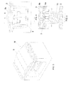
- the system of the invention includes a speed bump (D) usually provided with rectilinear structure, designed to cover the entire width of a carriageway.
- the said bump (D) is shown in working position, protruding from the carriageway; in rest position, the same bump (D) is designed to be "lowered” in order to be perfectly flush with the road surface.
- Two infrared devices (104) are installed on posts at the sides of the speed bump (D), for remote speed detection, being aimed at opposite directions in order to monitor traffic in both directions.
- the speed bump (D) will be either maintained in rest position or brought in working position, as shown in fig. 1 .
- the speed bump of the invention (D) may also be associated with one speed detector only, since the need to slow down vehicles is often required in one direction only.
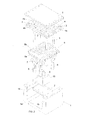
- the bump of the invention (D) is provided with modular structure, which is composed from time to time of the correct number of identical modules (M) designed to operate in perfect coordination.
- each module (M) is made of a basically U-shaped bearing frame designed to be inserted and fixed in transversal direction into the corresponding housing obtained in the road surface.
- the frame (1) includes a horizontal bearing wall (1 a) with rectangular shape, with two identical wings (1 b) protruding from the sides.
- a rectangular platform (2) is fixed in central position on the upper side of the said bearing wall (1 a) between the two vertical wings (1 b).
- Two opposite pairs of uprights (3) are fixed above the platform (2) at the two longitudinal ends of the platform (2), being designed to support a horizontal grid (4) having exactly the same area and rectangular section as the horizontal bottom wall (1 a) of the frame (1).
- the two transversal borders (4a) of the rectangular grid (4) are designed to be fitted on top of the vertical wings (1 b) of the frame (1) and suitably screwed in.
- the two longitudinal ends of the grid (4) are fitted to the transversal borders of a strip (5) made of rubber or any other elastically stretchable material, designed to exactly cover the surface of the grid (4).
- the short columns (6) are designed to be exactly inserted into corresponding bushes (7) fixed under a grated head (8) that operates under the grid (4).
- the grated head (8) is composed of a rectangular plate (8a) with horizontal direction, above which some transversal partitions (8b) in edgeways position with upper convex curved section are mounted and regularly spaced.
- Each partition (8b) is suitably dimensioned and positioned in order to be exactly inserted, from down upwards, into a corresponding longitudinal slot (4b) of the grid (4); the length of the bearing plate (8a) is such that it occupies the space bordered by the two pairs of uprights (3) under the grid (4).
- the grated head (8) is designed to slide vertically in parallel direction, together with the stem (9) of the hydraulic cylinder (10) from a lower stop position to an upper stop position.
- the grated head (8) is in lower stop position, which corresponds to a height in which the convex partitions (8b) are maintained inside the corresponding slots (4b) of the grid (4) without protruding from the top.
- the convex partitions (8b) of the grated head (8) protrude from the road surface, thus adequately interfering with a vehicle approaching at excessive speed.
- the various modules (M) of the speed bump (D) - or, more precisely, their hydraulic pistons (10) - are connected to the same hydraulic circuit (100) provided with a pressure regulator (101), and a valve (102) designed to close and open the circuit (100) and therefore alternatively actuate the hydraulic pistons (10) of the various modules (M).
- the same system also includes an electrical circuit for the automatic control of the said valve (102) of the hydraulic circuit.
- the electrical circuit includes an acoustic sensor (103), one or two infrared sensors (104) for remote speed detection, a manual switch (105) and two safety stops (106, 107).
- the two safety stops (106, 107) consist in two photocells mounted near the ground, one immediately upstream and one immediately downstream the speed bump (D), in such a way that the luminous rays cross the entire carriageway.
- the two photocells (106, 107) immediately detect the passage of vehicles over the bump (D) when they interrupt the luminous rays.
- the hydraulic cylinders (10) of the various modules (M) of the speed bump (D) are actuated, thus "raising" the speed bump (D), when one of the infrared sensors (104) detects an approaching vehicle with excessive speed.
- control to restore the rest position of the speed bump (D) is given as soon as the two photocells (106, 107) detect that the vehicle for which the speed bump (D) was raised has completely passed over the said bump (D).
- the photocells (106, 107) are also designed to carry out another important function in the system of the invention: to prevent the speed bump (D) from assuming the working position every time a vehicle stops over the said bump (D).
- the photocells (106, 107) are able to prevent the speed bump (D) from assuming the working position while a vehicle stopped "astride" the bump interrupts the luminous rays.
- the function of the acoustic sensor (103) is to capture the siren sound of emergency vehicles (fire brigade, ambulances, police, etc.) and temporarily exclude the operation of the infrared speed detectors (104).
- the system of the invention is provided with a manual switch (105) used to permanently "block” the speed bump (D) in working or rest position, until the same switch is actuated again.
- hydraulic cylinders (10) designed to raise the speed bump (D) may be replaced with different actuators with similar capacity.
- the infrared sensor (104) may be replaced with a different remote speed detector, such as, for instance, sensors composed of two electrical cables drowned transversally in the road surface that are able to determine the speed of an approaching vehicle by detecting the weight of the vehicle and calculating the time taken to cover the distance between the two transversal cables.
- a different remote speed detector such as, for instance, sensors composed of two electrical cables drowned transversally in the road surface that are able to determine the speed of an approaching vehicle by detecting the weight of the vehicle and calculating the time taken to cover the distance between the two transversal cables.
Landscapes
- Engineering & Computer Science (AREA)
- Architecture (AREA)
- Civil Engineering (AREA)
- Structural Engineering (AREA)
- Road Signs Or Road Markings (AREA)
- Transplanting Machines (AREA)
- Gear-Shifting Mechanisms (AREA)
- Vehicle Body Suspensions (AREA)
- Traffic Control Systems (AREA)
Claims (12)
- Versenkbare Anlage zur Geschwindigkeitssenkung des Straßenverkehrs, umfassend eine Bremsschwelle (D), bestehend aus mehreren Modulen (M), untergebracht in einem dazugehörigen Gehäuse in der Nähe der Fahrbahn und verbunden mit geeigneten Betätigungselementen (10), dazu befähigt, unverzüglich von einer vollkommen im Inneren des Gehäuses versenkten Ruhestellung in eine teilweise aus der Fläche der Fahrbahn auskragende Arbeitsstellung zu wechseln, wenn ein oder mehrere, mit ihr zusammenarbeitende Geschwindigkeitsdetektoren (104) mit Fernübertragung das Herannahen eines Fahrzeugs mit überhöhter Geschwindigkeit feststellt, und außerdem dazu befähigt, unverzüglich wieder in ihre Ruhestellung zurückzukehren, wenn ein oder mehrere, mit ihr zusammenarbeitende Sensoren (106, 107) feststellen, dass das Fahrzeug die Bremsschwelle (D) überfahren hat,
dadurch gekennzeichnet, dass jedes Modul (M) der Bremsschwelle (D) Folgendes umfasst:- einen im Wesentlichen U-förmigen Rahmen (1), der aus einer horizontalen Wand (1a) gebildet wird, aus deren Seiten zwei gegenüberliegende, identische Flügel (1 b) nach oben auskragen,- eine Plattform (2), die in der Mitte der Oberseite der horizontalen Wand (1a) des Rahmens (1) quer in einer Stellung zwischen den beiden vertikalen Flügeln (1 b) befestigt ist,- ein Betätigungselement (10), das oberhalb der Plattform (2) befestigt und dazu geeignet ist, einen Schaft (9) zu betätigen, der in der Lage ist, alternierende, vertikale Verfahrwege auszuführen,- einen Gitterkopf (8), der am oberen Ende des Schafts (9) befestigt ist und aus einer rechteckigen Platte (8a) in horizontaler Stellung besteht, über der einige regelmäßig beabstandete, querlaufende, kreuzweise angeordnete Trennwände (8b) montiert sind, die oberseitig mit einem konvex gebogenen Profil versehen sind,- ein horizontales Gitter (4), das durch an der Plattform befestigte Ständer (3) oberhalb des Gitterkopfes (8) gehalten wird; wobei vorgesehen ist, dass jeder Schlitz (4b) genau eine der querlaufenden Trennwände (8b) des Gitterkopfes (8) derart aufnimmt, dass bei den alternierenden, vertikalen Verfahrwegen des Gitterkopfes (8) jede querlaufende Trennwand (8b) aus einer unteren Endanschlagstellung, bei welcher ihr oberes, konvexes Profil in dem entsprechenden Schlitz (4b) eingesteckt bleibt, in eine obere Endanschlagstellung gebracht wird, in der sie beträchtlich über den Schlitz (4b) hinaus übersteht,- ein elastisch dehnbares Band (5), das in der Lage ist, die obere Fläche des Gitters (4) exakt zu bedecken, da es an den Enden auf den Querkanten (4a) des Gitters (4) befestigt wird. - Anlage nach Anspruch 1, dadurch gekennzeichnet, dass sie einen akustischen Sensor (103) umfasst, der in der Lage ist, das Anheben der Bremsschwelle (D) zu verhindern, wenn er den Sirenenton eines sich nähernden Rettungsfahrzeugs feststellt.
- Anlage nach dem ersten Anspruch oder beiden vorstehenden Ansprüchen, dadurch gekennzeichnet, dass sie einen manuell zu betätigenden Schalter (105) zur Dauersperrung der Bremsschwelle (D) in ihrer Arbeitsstellung oder in ihrer Ruhestellung umfasst.
- Anlage nach einem oder mehreren der vorstehenden Ansprüche, dadurch gekennzeichnet, dass ein oder mehrere Sensoren (106, 107) in der Lage sind, das Anheben der Bremsschwelle (D) zu verhindern, wenn das Vorhandensein eines über der Bremsschwelle geparkten Fahrzeugs festgestellt wird.
- Anlage nach einem oder mehreren der vorstehenden Ansprüche, dadurch gekennzeichnet, dass die Bremsschwelle (D) aus einer Reihe von zusammenwirkenden, identischen, nebeneinander angeordneten Modulen (M) besteht, die jeweils an ihrer Spitze ein Band (5) aus Gummi oder anderen, elastisch dehnbaren Materialien aufweisen, das horizontal, bündig mit der Fahrbahn abschließend angeordnet, gleichzeitig aber auch dazu bestimmt ist, dem von unten nach oben wirkenden Eingriff eines entsprechend geformten Kopfes (8) ausgesetzt zu werden, der kurz aus seinem Gehäuse im Straßenbett hervortritt und in der Lage ist, ihm eine konvex gebogene Stellung aufzuzwingen.
- Anlage nach einem beliebigen der vorstehenden Ansprüche, dadurch gekennzeichnet, dass das Gitter (4) unterseitig einige kurze Säulen (6) in vertikaler Stellung aufweist, die dazu geeignet sind, exakt in entsprechende Buchsen (7) einzufallen, die unterhalb des Gitterkopfes (8) derart befestigt sind, dass die ersten in der Lage sind, die alternierenden, vertikalen Verfahrwege der zweiten zu führen.
- Anlage nach einem oder mehreren der vorstehenden Ansprüche, dadurch gekennzeichnet, dass die Betätigungselemente (10), die zum Anheben und Absenken der Bremsschwelle (D) bestimmt sind, hydraulisch betätigt werden.
- Anlage nach den vorstehenden Ansprüchen 1 bis 6, dadurch gekennzeichnet, dass die Betätigungselemente (10), die zum Anheben und Absenken der Bremsschwelle (D) bestimmt sind, pneumatisch betätigt werden.
- Anlage nach einem oder mehreren der Ansprüche 1 bis 6, dadurch gekennzeichnet, dass die Betätigungselemente (10), die zum Anheben und Absenken der Bremsschwelle (D) bestimmt sind, elektromechanisch betätigt werden.
- Anlage nach einem oder mehreren der vorstehenden Ansprüche, dadurch gekennzeichnet, dass der eine oder die mehreren Geschwindigkeitsdetektoren mit Fernübertragung aus ebenso vielen Infrarotdetektoren (104) bestehen.
- Anlage nach einem oder mehreren der Ansprüche 1 bis 9, dadurch gekennzeichnet, dass der eine oder die mehreren Geschwindigkeitsdetektoren mit Fernübertragung in die Fahrbahn eingesenkt und in der Lage sind, das Gewicht der sich nähernden Fahrzeuge festzustellen.
- Anlage nach einem oder mehreren der vorstehenden Ansprüche, dadurch gekennzeichnet, dass die Sensoren (106, 107) optische Sensoren sind.
Applications Claiming Priority (1)
| Application Number | Priority Date | Filing Date | Title |
|---|---|---|---|
| IT000105A ITMC20070105A1 (it) | 2007-05-23 | 2007-05-23 | Impianto rallentatore stradale a scomparsa. |
Publications (3)
| Publication Number | Publication Date |
|---|---|
| EP1995381A2 EP1995381A2 (de) | 2008-11-26 |
| EP1995381A3 EP1995381A3 (de) | 2009-08-12 |
| EP1995381B1 true EP1995381B1 (de) | 2015-07-22 |
Family
ID=39683642
Family Applications (1)
| Application Number | Title | Priority Date | Filing Date |
|---|---|---|---|
| EP08103749.1A Active EP1995381B1 (de) | 2007-05-23 | 2008-04-28 | Eingebautes Geschwindigkeitsverringerungssystem für Straßenverkehr |
Country Status (2)
| Country | Link |
|---|---|
| EP (1) | EP1995381B1 (de) |
| IT (1) | ITMC20070105A1 (de) |
Cited By (1)
| Publication number | Priority date | Publication date | Assignee | Title |
|---|---|---|---|---|
| US9677232B2 (en) | 2015-09-17 | 2017-06-13 | Robert C. Zwerneman | Retractable speed barrier |
Families Citing this family (8)
| Publication number | Priority date | Publication date | Assignee | Title |
|---|---|---|---|---|
| US10648141B2 (en) | 2016-08-10 | 2020-05-12 | The Board Of Regents Of The Nevada System Of Higher Education On Behalf Of The University Of Nevada, Las Vegas | Automated rumble strip assembly |
| US10829900B2 (en) | 2016-08-10 | 2020-11-10 | The Board Of Regents Of The Nevada System Of Higher Education On Behalf Of The University Of Nevada, Las Vegas | Automated rumble strip assembly |
| CN108842646A (zh) * | 2017-03-01 | 2018-11-20 | 六安永贞匠道机电科技有限公司 | 应用于智能化交通建设的车辆减速设备 |
| CN106875748B (zh) * | 2017-03-16 | 2023-03-07 | 上海市城市建设设计研究总院(集团)有限公司 | 人行横道智能防冲撞系统的控制方法 |
| CN107974956A (zh) * | 2017-11-21 | 2018-05-01 | 安徽省宿州市第二中学 | 一种智能减速带 |
| WO2019156882A1 (en) * | 2018-02-09 | 2019-08-15 | The Board Of Regents Of The Nevada System Of Higher Education On Behalf Of The University Of Nevada, Las Vegas | Automated rumble strip assembly |
| CN108442264A (zh) * | 2018-03-29 | 2018-08-24 | 南京亚欣照明有限公司 | 一种具有地埋灯的市政隧道警示装置 |
| CN110578303A (zh) * | 2018-06-11 | 2019-12-17 | 徐勇 | 一种建筑工地用路面减速隔离装置 |
Family Cites Families (6)
| Publication number | Priority date | Publication date | Assignee | Title |
|---|---|---|---|---|
| NL1011259C1 (nl) * | 1999-02-10 | 2000-08-11 | Edzo Hilbert Keijer | Verkeersdrempel. |
| SE0203458L (sv) * | 2002-11-21 | 2004-05-22 | Peak Innovation Ab | Väghinder |
| US7011470B1 (en) * | 2004-03-29 | 2006-03-14 | Orville Alan Breazeale | Retractable speed bump |
| GB2418445B (en) * | 2004-09-23 | 2009-06-17 | David Griffiths | Retractable speed bump |
| GB2428067A (en) * | 2005-07-07 | 2007-01-17 | Stephen Shaw | Dynamic speed hump |
| SE530061C2 (sv) * | 2005-10-20 | 2008-02-19 | Safezone Traffic System Ab | Styrbart farthinder |
-
2007
- 2007-05-23 IT IT000105A patent/ITMC20070105A1/it unknown
-
2008
- 2008-04-28 EP EP08103749.1A patent/EP1995381B1/de active Active
Cited By (1)
| Publication number | Priority date | Publication date | Assignee | Title |
|---|---|---|---|---|
| US9677232B2 (en) | 2015-09-17 | 2017-06-13 | Robert C. Zwerneman | Retractable speed barrier |
Also Published As
| Publication number | Publication date |
|---|---|
| EP1995381A2 (de) | 2008-11-26 |
| ITMC20070105A1 (it) | 2008-11-24 |
| EP1995381A3 (de) | 2009-08-12 |
Similar Documents
| Publication | Publication Date | Title |
|---|---|---|
| EP1995381A2 (de) | Eingebautes Geschwindigkeitsverringerungssystem für Straßenverkehr | |
| US6926462B1 (en) | Retractable road barrier | |
| US5486065A (en) | Traffic speed control unit and assembly | |
| EP3655588B1 (de) | Vorrichtung mit elektrischer oder pneumatischer betätigung eines klappmechanismus zur anregung zur verringerung der fahrzeuggeschwindigkeit | |
| CA2465431A1 (en) | Method for decelerating a vehicle, highway crash cushion, and energy absorbing element therefor | |
| KR102052407B1 (ko) | 스마트 승강형 경광조명장치 | |
| CN210288203U (zh) | 一种用于平面交叉路口非机动车道的管控系统 | |
| KR102598190B1 (ko) | 신호 연동형 횡단보도 보행자 안전장치 | |
| WO2017080124A1 (zh) | 可移动天桥系统 | |
| CN111210642A (zh) | 一种具有高度警示性的智能化红绿灯 | |
| CN111986475A (zh) | 一种桥梁承重地磅监测管理预警系统及操作方法 | |
| KR102427167B1 (ko) | 재난방재용 차량 통제장치 | |
| CN113605277A (zh) | 一种用于市政桥梁限高限行的智能系统 | |
| KR20180093627A (ko) | 승강형 경광 조명장치 및 이를 이용한 드론시스템 | |
| GB2304769A (en) | Traffic calming device | |
| KR20240164678A (ko) | 비상 알림기능이 개선된 도로교통안전시설물 | |
| WO1999002387A1 (es) | Instalacion de vallas de seguridad para evitar caidas desde un anden a una via | |
| CN111379232B (zh) | 用于平面交叉路口非机动车道的管控系统 | |
| CN111535101B (zh) | 一种十字路口车辆通行下穿隧道及其通行方法 | |
| CN210420935U (zh) | 一种小车尾箱安检设备 | |
| CN114457709A (zh) | 一种城市交叉口人行道用的自动升降的安全隔离墩的使用方法 | |
| CN115731691B (zh) | 一种基于视频检测的行人过街安全防护系统 | |
| KR20050040870A (ko) | 과속방지 및 정보제공용 차량차단기 | |
| CH708132A1 (de) | Sicherheitssystem an Fussgängerstreifen. | |
| CN114399923B (zh) | 一种基于plc控制的隧道交通雷达警示系统 |
Legal Events
| Date | Code | Title | Description |
|---|---|---|---|
| PUAI | Public reference made under article 153(3) epc to a published international application that has entered the european phase |
Free format text: ORIGINAL CODE: 0009012 |
|
| AK | Designated contracting states |
Kind code of ref document: A2 Designated state(s): AT BE BG CH CY CZ DE DK EE ES FI FR GB GR HR HU IE IS IT LI LT LU LV MC MT NL NO PL PT RO SE SI SK TR |
|
| AX | Request for extension of the european patent |
Extension state: AL BA MK RS |
|
| PUAL | Search report despatched |
Free format text: ORIGINAL CODE: 0009013 |
|
| AK | Designated contracting states |
Kind code of ref document: A3 Designated state(s): AT BE BG CH CY CZ DE DK EE ES FI FR GB GR HR HU IE IS IT LI LT LU LV MC MT NL NO PL PT RO SE SI SK TR |
|
| AX | Request for extension of the european patent |
Extension state: AL BA MK RS |
|
| 17P | Request for examination filed |
Effective date: 20100203 |
|
| AKX | Designation fees paid |
Designated state(s): AT BE BG CH CY CZ DE DK EE ES FI FR GB GR HR HU IE IS IT LI LT LU LV MC MT NL NO PL PT RO SE SI SK TR |
|
| 17Q | First examination report despatched |
Effective date: 20130607 |
|
| GRAP | Despatch of communication of intention to grant a patent |
Free format text: ORIGINAL CODE: EPIDOSNIGR1 |
|
| INTG | Intention to grant announced |
Effective date: 20150210 |
|
| GRAS | Grant fee paid |
Free format text: ORIGINAL CODE: EPIDOSNIGR3 |
|
| GRAA | (expected) grant |
Free format text: ORIGINAL CODE: 0009210 |
|
| AK | Designated contracting states |
Kind code of ref document: B1 Designated state(s): AT BE BG CH CY CZ DE DK EE ES FI FR GB GR HR HU IE IS IT LI LT LU LV MC MT NL NO PL PT RO SE SI SK TR |
|
| REG | Reference to a national code |
Ref country code: GB Ref legal event code: FG4D |
|
| REG | Reference to a national code |
Ref country code: CH Ref legal event code: EP |
|
| REG | Reference to a national code |
Ref country code: IE Ref legal event code: FG4D |
|
| REG | Reference to a national code |
Ref country code: AT Ref legal event code: REF Ref document number: 738008 Country of ref document: AT Kind code of ref document: T Effective date: 20150815 |
|
| REG | Reference to a national code |
Ref country code: DE Ref legal event code: R096 Ref document number: 602008039109 Country of ref document: DE |
|
| REG | Reference to a national code |
Ref country code: AT Ref legal event code: MK05 Ref document number: 738008 Country of ref document: AT Kind code of ref document: T Effective date: 20150722 |
|
| REG | Reference to a national code |
Ref country code: DE Ref legal event code: R079 Ref document number: 602008039109 Country of ref document: DE Free format text: PREVIOUS MAIN CLASS: E01F0009047000 Ipc: E01F0009529000 |
|
| REG | Reference to a national code |
Ref country code: LT Ref legal event code: MG4D |
|
| REG | Reference to a national code |
Ref country code: NL Ref legal event code: MP Effective date: 20150722 |
|
| PG25 | Lapsed in a contracting state [announced via postgrant information from national office to epo] |
Ref country code: NO Free format text: LAPSE BECAUSE OF FAILURE TO SUBMIT A TRANSLATION OF THE DESCRIPTION OR TO PAY THE FEE WITHIN THE PRESCRIBED TIME-LIMIT Effective date: 20151022 Ref country code: LT Free format text: LAPSE BECAUSE OF FAILURE TO SUBMIT A TRANSLATION OF THE DESCRIPTION OR TO PAY THE FEE WITHIN THE PRESCRIBED TIME-LIMIT Effective date: 20150722 Ref country code: GR Free format text: LAPSE BECAUSE OF FAILURE TO SUBMIT A TRANSLATION OF THE DESCRIPTION OR TO PAY THE FEE WITHIN THE PRESCRIBED TIME-LIMIT Effective date: 20151023 Ref country code: LV Free format text: LAPSE BECAUSE OF FAILURE TO SUBMIT A TRANSLATION OF THE DESCRIPTION OR TO PAY THE FEE WITHIN THE PRESCRIBED TIME-LIMIT Effective date: 20150722 Ref country code: FI Free format text: LAPSE BECAUSE OF FAILURE TO SUBMIT A TRANSLATION OF THE DESCRIPTION OR TO PAY THE FEE WITHIN THE PRESCRIBED TIME-LIMIT Effective date: 20150722 |
|
| PG25 | Lapsed in a contracting state [announced via postgrant information from national office to epo] |
Ref country code: SE Free format text: LAPSE BECAUSE OF FAILURE TO SUBMIT A TRANSLATION OF THE DESCRIPTION OR TO PAY THE FEE WITHIN THE PRESCRIBED TIME-LIMIT Effective date: 20150722 Ref country code: HR Free format text: LAPSE BECAUSE OF FAILURE TO SUBMIT A TRANSLATION OF THE DESCRIPTION OR TO PAY THE FEE WITHIN THE PRESCRIBED TIME-LIMIT Effective date: 20150722 Ref country code: AT Free format text: LAPSE BECAUSE OF FAILURE TO SUBMIT A TRANSLATION OF THE DESCRIPTION OR TO PAY THE FEE WITHIN THE PRESCRIBED TIME-LIMIT Effective date: 20150722 Ref country code: ES Free format text: LAPSE BECAUSE OF FAILURE TO SUBMIT A TRANSLATION OF THE DESCRIPTION OR TO PAY THE FEE WITHIN THE PRESCRIBED TIME-LIMIT Effective date: 20150722 Ref country code: PT Free format text: LAPSE BECAUSE OF FAILURE TO SUBMIT A TRANSLATION OF THE DESCRIPTION OR TO PAY THE FEE WITHIN THE PRESCRIBED TIME-LIMIT Effective date: 20151123 Ref country code: IS Free format text: LAPSE BECAUSE OF FAILURE TO SUBMIT A TRANSLATION OF THE DESCRIPTION OR TO PAY THE FEE WITHIN THE PRESCRIBED TIME-LIMIT Effective date: 20151122 Ref country code: PL Free format text: LAPSE BECAUSE OF FAILURE TO SUBMIT A TRANSLATION OF THE DESCRIPTION OR TO PAY THE FEE WITHIN THE PRESCRIBED TIME-LIMIT Effective date: 20150722 |
|
| REG | Reference to a national code |
Ref country code: DE Ref legal event code: R097 Ref document number: 602008039109 Country of ref document: DE |
|
| PG25 | Lapsed in a contracting state [announced via postgrant information from national office to epo] |
Ref country code: SK Free format text: LAPSE BECAUSE OF FAILURE TO SUBMIT A TRANSLATION OF THE DESCRIPTION OR TO PAY THE FEE WITHIN THE PRESCRIBED TIME-LIMIT Effective date: 20150722 Ref country code: CZ Free format text: LAPSE BECAUSE OF FAILURE TO SUBMIT A TRANSLATION OF THE DESCRIPTION OR TO PAY THE FEE WITHIN THE PRESCRIBED TIME-LIMIT Effective date: 20150722 Ref country code: DK Free format text: LAPSE BECAUSE OF FAILURE TO SUBMIT A TRANSLATION OF THE DESCRIPTION OR TO PAY THE FEE WITHIN THE PRESCRIBED TIME-LIMIT Effective date: 20150722 Ref country code: EE Free format text: LAPSE BECAUSE OF FAILURE TO SUBMIT A TRANSLATION OF THE DESCRIPTION OR TO PAY THE FEE WITHIN THE PRESCRIBED TIME-LIMIT Effective date: 20150722 |
|
| PLBE | No opposition filed within time limit |
Free format text: ORIGINAL CODE: 0009261 |
|
| STAA | Information on the status of an ep patent application or granted ep patent |
Free format text: STATUS: NO OPPOSITION FILED WITHIN TIME LIMIT |
|
| PG25 | Lapsed in a contracting state [announced via postgrant information from national office to epo] |
Ref country code: RO Free format text: LAPSE BECAUSE OF FAILURE TO SUBMIT A TRANSLATION OF THE DESCRIPTION OR TO PAY THE FEE WITHIN THE PRESCRIBED TIME-LIMIT Effective date: 20150722 |
|
| 26N | No opposition filed |
Effective date: 20160425 |
|
| PG25 | Lapsed in a contracting state [announced via postgrant information from national office to epo] |
Ref country code: BE Free format text: LAPSE BECAUSE OF NON-PAYMENT OF DUE FEES Effective date: 20160430 Ref country code: SI Free format text: LAPSE BECAUSE OF FAILURE TO SUBMIT A TRANSLATION OF THE DESCRIPTION OR TO PAY THE FEE WITHIN THE PRESCRIBED TIME-LIMIT Effective date: 20150722 |
|
| REG | Reference to a national code |
Ref country code: DE Ref legal event code: R119 Ref document number: 602008039109 Country of ref document: DE |
|
| REG | Reference to a national code |
Ref country code: CH Ref legal event code: PL |
|
| GBPC | Gb: european patent ceased through non-payment of renewal fee |
Effective date: 20160428 |
|
| PG25 | Lapsed in a contracting state [announced via postgrant information from national office to epo] |
Ref country code: BE Free format text: LAPSE BECAUSE OF FAILURE TO SUBMIT A TRANSLATION OF THE DESCRIPTION OR TO PAY THE FEE WITHIN THE PRESCRIBED TIME-LIMIT Effective date: 20150722 Ref country code: LU Free format text: LAPSE BECAUSE OF FAILURE TO SUBMIT A TRANSLATION OF THE DESCRIPTION OR TO PAY THE FEE WITHIN THE PRESCRIBED TIME-LIMIT Effective date: 20160428 |
|
| REG | Reference to a national code |
Ref country code: IE Ref legal event code: MM4A |
|
| REG | Reference to a national code |
Ref country code: FR Ref legal event code: ST Effective date: 20161230 |
|
| PG25 | Lapsed in a contracting state [announced via postgrant information from national office to epo] |
Ref country code: GB Free format text: LAPSE BECAUSE OF NON-PAYMENT OF DUE FEES Effective date: 20160428 Ref country code: CH Free format text: LAPSE BECAUSE OF NON-PAYMENT OF DUE FEES Effective date: 20160430 Ref country code: FR Free format text: LAPSE BECAUSE OF NON-PAYMENT OF DUE FEES Effective date: 20160502 Ref country code: DE Free format text: LAPSE BECAUSE OF NON-PAYMENT OF DUE FEES Effective date: 20161101 Ref country code: LI Free format text: LAPSE BECAUSE OF NON-PAYMENT OF DUE FEES Effective date: 20160430 |
|
| PG25 | Lapsed in a contracting state [announced via postgrant information from national office to epo] |
Ref country code: IE Free format text: LAPSE BECAUSE OF NON-PAYMENT OF DUE FEES Effective date: 20160428 |
|
| PG25 | Lapsed in a contracting state [announced via postgrant information from national office to epo] |
Ref country code: NL Free format text: LAPSE BECAUSE OF FAILURE TO SUBMIT A TRANSLATION OF THE DESCRIPTION OR TO PAY THE FEE WITHIN THE PRESCRIBED TIME-LIMIT Effective date: 20150722 |
|
| PG25 | Lapsed in a contracting state [announced via postgrant information from national office to epo] |
Ref country code: HU Free format text: LAPSE BECAUSE OF FAILURE TO SUBMIT A TRANSLATION OF THE DESCRIPTION OR TO PAY THE FEE WITHIN THE PRESCRIBED TIME-LIMIT; INVALID AB INITIO Effective date: 20080428 Ref country code: CY Free format text: LAPSE BECAUSE OF FAILURE TO SUBMIT A TRANSLATION OF THE DESCRIPTION OR TO PAY THE FEE WITHIN THE PRESCRIBED TIME-LIMIT Effective date: 20150722 |
|
| PG25 | Lapsed in a contracting state [announced via postgrant information from national office to epo] |
Ref country code: TR Free format text: LAPSE BECAUSE OF FAILURE TO SUBMIT A TRANSLATION OF THE DESCRIPTION OR TO PAY THE FEE WITHIN THE PRESCRIBED TIME-LIMIT Effective date: 20150722 Ref country code: MC Free format text: LAPSE BECAUSE OF FAILURE TO SUBMIT A TRANSLATION OF THE DESCRIPTION OR TO PAY THE FEE WITHIN THE PRESCRIBED TIME-LIMIT Effective date: 20150722 Ref country code: MT Free format text: LAPSE BECAUSE OF NON-PAYMENT OF DUE FEES Effective date: 20160430 |
|
| PG25 | Lapsed in a contracting state [announced via postgrant information from national office to epo] |
Ref country code: BG Free format text: LAPSE BECAUSE OF FAILURE TO SUBMIT A TRANSLATION OF THE DESCRIPTION OR TO PAY THE FEE WITHIN THE PRESCRIBED TIME-LIMIT Effective date: 20150722 |
|
| PGFP | Annual fee paid to national office [announced via postgrant information from national office to epo] |
Ref country code: IT Payment date: 20250319 Year of fee payment: 18 |