EP1447005A2 - Teigbearbeitungsanlage - Google Patents
Teigbearbeitungsanlage Download PDFInfo
- Publication number
- EP1447005A2 EP1447005A2 EP04000466A EP04000466A EP1447005A2 EP 1447005 A2 EP1447005 A2 EP 1447005A2 EP 04000466 A EP04000466 A EP 04000466A EP 04000466 A EP04000466 A EP 04000466A EP 1447005 A2 EP1447005 A2 EP 1447005A2
- Authority
- EP
- European Patent Office
- Prior art keywords
- dough
- drive
- portioning
- delivery piston
- processing plant
- Prior art date
- Legal status (The legal status is an assumption and is not a legal conclusion. Google has not performed a legal analysis and makes no representation as to the accuracy of the status listed.)
- Granted
Links
- 238000012545 processing Methods 0.000 title claims description 25
- 238000009434 installation Methods 0.000 title 1
- 238000012546 transfer Methods 0.000 claims abstract description 6
- 238000009940 knitting Methods 0.000 claims 1
- 238000004898 kneading Methods 0.000 abstract description 10
- 238000005259 measurement Methods 0.000 abstract description 3
- 230000005540 biological transmission Effects 0.000 description 32
- 230000033001 locomotion Effects 0.000 description 19
- 230000009471 action Effects 0.000 description 7
- 230000008859 change Effects 0.000 description 3
- 230000002093 peripheral effect Effects 0.000 description 3
- 238000005086 pumping Methods 0.000 description 2
- 238000001228 spectrum Methods 0.000 description 2
- 235000008429 bread Nutrition 0.000 description 1
- 238000005253 cladding Methods 0.000 description 1
- 210000001520 comb Anatomy 0.000 description 1
- 238000006073 displacement reaction Methods 0.000 description 1
- 238000002474 experimental method Methods 0.000 description 1
- 230000006870 function Effects 0.000 description 1
- 230000001939 inductive effect Effects 0.000 description 1
- 230000007246 mechanism Effects 0.000 description 1
- 230000009467 reduction Effects 0.000 description 1
- 238000009333 weeding Methods 0.000 description 1
Images


Classifications
-
- A—HUMAN NECESSITIES
- A21—BAKING; EDIBLE DOUGHS
- A21C—MACHINES OR EQUIPMENT FOR MAKING OR PROCESSING DOUGHS; HANDLING BAKED ARTICLES MADE FROM DOUGH
- A21C5/00—Dough-dividing machines
- A21C5/02—Dough-dividing machines with division boxes and ejection plungers
Definitions
- the invention relates to a dough processing plant according to the preamble of claim 1.
- Such a dough processing plant is by public prior use known.
- the force of the delivery piston on the dough Portioning limited by means of springs or by means of a hydraulic device.
- a limitation of the piston force is required because the amount of dough delivered correspond to the volume of all Portionierhuntn got to.
- the movement must of the delivery piston are stopped. If this does not happen in time, the pressure in the dough increases, which negatively affects the product quality can.
- the force measuring device ensures that the pressure of the delivery piston can be monitored on the dough while portioning it. On this way, pressure values can be prevented from being reached can lead to damage to the dough. A good product quality can therefore be guaranteed.
- a force measuring device can be practically any Locating the power transmission within the drive device for the Insert delivery piston.
- a load cell according to claim 3 leads to an economically feasible Force measuring device.
- Such measuring boxes are in a variety of designs known.
- An arrangement of the load cell according to claim 4 leads to a force measurement free of external interference.
- a control device leads to the possibility of an automatic Actuation of the delivery piston, wherein it is ensured that the preset pressure limit is not exceeded.
- the pressure limit can be determined empirically in the experiment, for example. Especially can be avoided with great certainty that the pressure of the delivery piston is too low to fill the Portionierhuntn. weight inaccuracies can be avoided.
- a control device leads to the possibility of movement of the delivery piston to the particular dough recipe used or to the size of the Portionierschn. When changing the dough processing plant from one dough recipe to another or from one portioning chamber size to another can be this way the delivery piston movement can be adjusted quickly.
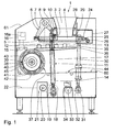
- a dough processing plant 1 is used for portioning and working of dough, for example in bread making.
- This is dough in one Feed hopper 2 filled.
- a bottom outlet opening 3 of the Zuzhoutrichters 2 communicates with a delivery chamber 4 in which a Delivery piston 5 runs horizontally.
- the horizontal conveying movement of the delivery piston 5 is driven by a crank mechanism 6.
- This is on a the delivery chamber 4 end facing away from the delivery piston 5, a first Lever arm 7 hinged, which rotatably at its other end with a Swivel shaft 8 is connected.
- a second lever arm 9 is also rotatably with the pivot shaft. 8 connected.
- a connecting member 12 in which a load cell 13 is arranged is the first connecting rod portion 10 at a second connecting rod portion 14 hinged.
- the arrangement of the load cell 13 in the connecting member 12 is such that measured by means of the load cell 13 of the pressure can be, the two connecting rod sections 10, 14 in the Conveying movement of the delivery piston 5 exercise each other.
- Via a signal line 15 is the load cell 13 with a control device 16 in Connection.
- the control device 16 has a rewritable Memory 16 a on.
- Load cells on the type of load cell 13 are known.
- the shape change the load cell 13 is a measure of the acting on this Print. This change in shape can capacitive, inductive or by the Measuring an electrical resistance change, for example of strain gauges, be measured.
- the two connecting rod sections 10, 14 and the connecting member 12 with the load cell 13 are guided in a connecting rod housing 17.
- the remote from the connecting member 12 end of the second connecting rod section 14 is hinged to a crankshaft 18, which via a drive chain 19 of a drive shaft 20 of a delivery piston drive motor 21 is driven. With the latter is via a control line 22 the Control device 16 connected.
- the dough is through the in Figs. 1 to 3 to the right moving delivery piston 5 pressed against Portionierhuntn 23 whose Cladding walls of portioning cylinders 24 are formed.
- the portioning combs 23 put in Figs. 1 to 3 the pumping chamber 4 to the right.
- the Portionierkammem 23 limited by portioning 25.
- At the dough processing plant 1 are perpendicular to the plane of Figs. 1 to 3 more Portioniervenezen each with a portioning chamber 23, a Portionierzylinder 24 and a portioning 25 arranged one behind the other.
- the portioning 25th is at its end remote from the pumping chamber 4 end to a portioning crankshaft 26 arranged in the in Figs. 1 to 3 in not shown Way is driven.
- a portioning stroke of the portioning pistons 25 is adjustable, whereby a desired volume of portioned dough pieces are achieved can.
- the portioning units are arranged in a flat slide box 27, the vertical slide wall 28 flush with end wall portions of a the delivery chamber 4 limiting and the delivery piston 5 leading support section 29 of the dough processing plant 1 is applied.
- the flat slide box 27 is along the vertical guidance of the slider wall 28 on the support portion 29 displaceable for portioning the dough.
- the flat valve box 27 hinged to a flat slide box connecting rod 30, at its other end to a flat valve box crankshaft 31st is articulated. The latter is via a drive chain 32 from a drive shaft 33 of a flat slide box drive motor 34 driven.
- Fig. 1 to 3 illustrate the portioning of dough pieces 35 with the Dough processing plant 1.
- Fig. 1 shows the dough processing plant. 1 in a dough-suction phase, in which the delivery piston 5 completely after is withdrawn on the left and in which the Portionierkolben 25 one to the left take displaced position in which their piston walls flush with the conveyor chamber 4 facing surface of the slide wall 28 complete.
- 2 shows the dough processing plant 1 during a dough-filling phase, in which the sucked dough by moving the delivery piston. 5 compressed to the right and pressed in the direction of Portionierhuntn 23 becomes.
- the portioning pistons 25 in the portioning cylinders 24 about the portioning stroke predetermined by the portioning crankshaft 26 shifted to the right, so that in the Portionierhuntn 23 a desired Dough volume can collect.
- the pressure with which the delivery piston 5 in the dough-filling phase on the compacted dough in the delivery chamber 4 and in the Portionierhuntn 23rd is measured by means of the load cell 13 and the signal line 15 transmitted to the control device 16. There is the measured Pressure with a stored in the memory 16 a of the controller 16 Limit value compared. When measured with the load cell 13 Pressure has reached the pressure limit, pushing the dough in the Portionierhuntn 23 completed by the delivery piston 5 and this is, for example in the position of Fig. 2, controlled by the control device 16 via the control line 22, stopped.
- the in the control device 16 stored pressure limit is in particular to the dough recipe and also adapted to the portion size.
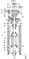
- the dough-effecting device 37 will be described below with additional reference to FIGS. 4 to 9 described. It has an inner hollow cylindrical Impeller 38, which rotatably via a support frame 39 with a central operating drum shaft 40 is connected. Coaxial around the inner Impact drum 38 is also referred to as a chamber drum, outer hollow cylindrical drum 41 is arranged. This is around the reel drum 40 rotatable relative to the inner drum 38 of the operating drum shaft 40 stored arranged.
- the outer action drum 41 has in known manner openings 42. These are outward and after inside open and are bounded inside by the outer wall of the inner action drum 38.
- the openings 42 are limited to the outside a spectrum 43 of an active / conveyor belt 44, which in this peripheral section is applied to the outer drum 41.
- the in this peripheral section All-round limited openings 42 form active cells 45.
- the knit / conveyor belt 44 is a multiply deflected endless conveyor belt executed.
- the inner active drum 38 and the outer active drum 41 lead to Act of the dough relative to each other by an active movement, by a designated generally by the reference numeral 46 active drive driven is.
- an unrepresented active drive motor acts over a transmission belt 47 on a transmission disc 48, the rotationally fixed is connected to a first transmission shaft 49.
- the latter is with a drive-side shaft of a Wirkantriebsgetriebes 50 connected.
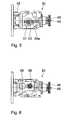
- the Wirkantriebsgetriebe 50 transmits the rotation of the transmission shaft 49 in a rotation of a transmission shaft 51 which is arranged between the transmission shaft 49 and the reel shaft 40 and whose axis of rotation 52 is perpendicular to the axis of rotation of the reel drum 40.
- an eccentric shaft 53 In a bore of the transmission shaft 51, an eccentric shaft 53, whose axis of rotation 54 extends parallel to the axis of rotation of the transmission shaft 51 and to this has a distance which is designated in Figs. 4 and 7 with E 2 .
- the eccentric shaft 53 is pivotable relative to the transmission shaft 51 about its axis of rotation 54. This Verschwenkweg is limited by a stop body 54a, which is rotatably connected to the eccentric shaft 53 and cooperates with a counter stop body 54b, which is designed as a stage in a stop body 54a facing end wall of the transmission shaft 51. Another counter-stop body 54c is also embodied in the end wall of the transmission shaft 51.
- the eccentric shaft 53 is connected via an eccentric connecting member 55 with a further eccentric shaft 56 in connection, whose axis of rotation 57 is arranged parallel to the axes of rotation 52 and 54.
- the distance between the axes of rotation 54, 57 of the eccentric shafts 53, 56 is designated E 1 in FIG. 4.
- the eccentric shaft 56 is arranged with respect to the transmission shaft 51 in the position of the active drive 46 in Figs. 4 to 6 such that the axis of rotation 52 of the transmission shaft 51 to the axis of rotation 57 of the eccentric shaft 56 has the distance E 1 + E 2 .
- the eccentric shaft 56 is connected via a ball joint with a transmission member 58 connected.
- the latter is via a further transmission element 59, which is rotatably mounted around the Wektrommelwelle 40, with the outer Impact drum 41 in conjunction.
- the two transmission members 58, 59 provide a second and a third Drive component of the active drive 46 and have the following function: On the one hand, via the transmission members 58, 59, the rotational movement the transmission shaft 59 in a rotational movement of the outer active drum 41 transmitted to the weir drum shaft 40. The rotational movements of the two operating drums 38, 41 are around the operating drum shaft 40 independent of each other. In this sense, the transmission links 58, 59 is a second drive component of the active drive 46. Further, the transmission members 58, 59 also transmit a motion component the outer active drum 41 relative to the inner active drum 38 parallel to the weeding drum shaft 40, driven by the rotation of the Exzenterwelle 56 to the transmission shaft 51.
- the Transmission members 58, 59 a third drive component of the active drive 46.
- the rotation of the outer active drum 41 around the inner Drum drum 38 and the movement of the outer drum 41 relatively to the inner drum 38 with movement component in parallel to the Longitudinal axis of the reel drum shaft 40 are matched to one another, that the openings 42 and in particular the active cells a circular Movement relative to the apertures 42 limiting Wall of the inner active drum 38 and relative to the spectrum 43 of the active conveyor belt 44 perform.
- the dough pieces in the active cells 35 are worked in this way, whereby the previously unformed Dough piece 35 is brought into a spherical shape.
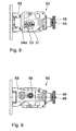
- a relative pivoting of the two eccentric shafts 53, 56 to each other by 180 ° is possible.
- the distances E 1 and E 2 subtract from each other, so that the axis of rotation 52 of the transmission shaft 51 and the axis of rotation 57 of the eccentric shaft 56 to each other at a distance of E 1 - E 2 have.
- the amount of the movement component of the relative movement of the outer active drum 41 to the inner active drum 38 is reduced parallel to the longitudinal axis of the reeling drum shaft 40.
- the dough action device 37 works as follows:
- the direction of rotation of the transmission shaft 49 and the difference in the rotational speeds between the inner drive drum 38th on the one hand and the outer active drum 41 on the other hand predetermined.
- the position of the active drive 46th achieved according to FIG. 4.
- a circular action movement be provided with a larger radius.
- the sense of rotation of Rotation of the transmission shaft 49 inversely.
- the active drive 46 then takes no later than after half a revolution, the position shown in FIG. 7, in which the circular action movement is provided with a smaller radius.
- the dough pieces 35 leave the active cells and are transferred to a conveying strand 60 of the kneading / conveyor belt 44 and leave a housing 61 of the dough processing plant 1 by a corresponding Dispensing opening.
Landscapes
- Life Sciences & Earth Sciences (AREA)
- Engineering & Computer Science (AREA)
- Food Science & Technology (AREA)
- Manufacturing And Processing Devices For Dough (AREA)
Abstract
Description
- Fig. 1
- einen Schnitt durch eine Teigbearbeitungsanlage als Momentaufnahme in einer Teig-Ansaug-Phase,
- Fig. 2 und 3
- Momentaufnahmen der Teigbearbeitungsanlage in einer Teig-Füll-Phase und in einer Teig-Ausstoß-Phase in einer zu Fig. 1 ähnlichen Darstellung, wobei dort eine Teig-Wirk-Vorrichtung sowie eine Teig-Abführ-Einrichtung sowie einige weitere Details der Teigbearbeitungsanlage gemäß Fig. 1 nicht dargestellt sind,
- Fig. 4
- einen Längsschnitt durch die Teig-Wirk-Vorrichtung der Teigbearbeitungsanlage bei maximalem Abstand zwischen der Achse einer ersten Exenterwelle und einer Getriebewelle eines Wirkantriebsgetriebes,
- Fig. 5
- eine erste Seitenansicht eines Wirkantriebsgetriebes der Teig-Wirk-Vorrichtung mit Blickrichtung auf die in Fig. 4 untenliegende Seite des Wirkantriebsgetriebes,
- Fig. 6
- eine weitere Seitenansicht des Wirkantriebsgetriebes mit Blick auf eine in Fig. 4 obenliegende Seite des Wirkantriebgetriebes,
- Fig. 7
- eine zur Fig. 4 ähnliche Darstellung der Teig-Wirk-Vorrichtung bei minimalem Abstand zwischen der Achse der ersten Exenterwelle und der Getriebewelle des Wirkantriebsgetriebes, und
- Fig. 8 und 9
- zu den Fig. 5 und 6 ähnliche Ansichten der Teig-Wirk-Vorrichtung in der Stellung der Fig. 7.
Claims (6)
- Teigbearbeitungsanlage (1)dadurch gekennzeichnet, dassmit einer Teig-Zuführeinrichtung (2),mit einer Teig-Portioniervorrichtung (5, 22 bis 27), die umfasst:mindestens einen Förderkolben (5), der zugeführten Teig in mindestens eine Portionierkammer (23) drückt,mindestens eine Antriebseinrichtung (6 bis 21) für den Förderkolben (5),mit einer Teig-Wirkvorrichtung (37),mit einer Übergabeeinrichtung (36), die eine Teigportion (35) von der Teig-Portioniervorrichtung (5, 23 bis 27) an die Teig-Wirkvorrichtung (37) übergibt undmit einer Teig-Abführeinrichtung (60),
mindestens eine Antriebskomponente (11) der Antriebseinrichtung (6 bis 21) für den Förderkolben (5) eine Kraftmesseinrichtung (13) aufweist, welche derart angeordnet ist, dass mit ihr die Kraft gemessen werden kann, welche der Förderkolben (5) beim Druck auf den Teig auf diesen ausübt. - Teigbearbeitungsanlage nach Anspruch 1, dadurch gekennzeichnet, dass die Kraftmesseinrichtung (13) mindestens einen Dehnungsmessstreifen umfasst.
- Teigbearbeitungsanlage nach Anspruch 1 oder 2, dadurch gekennzeichnet, dass die Kraftmesseinrichtung (13) als Messdose zwischen zwei Antriebsteilen (10, 14) der Antriebseinrichtung (6 bis 21) ausgeführt ist.
- Teigbearbeitungsanlage nach Anspruch 3, dadurch gekennzeichnet, dass die Kraftmesseinrichtung (13) in einem rohrförmigen Gehäuse (17) zwischen zwei Stangenabschnitten (10, 14) einer Antriebsstange (11), insbesondere einer Pleuelstange, angeordnet ist.
- Teigbearbeitungsanlage nach einem der vorherigen Ansprüche, gekennzeichnet durch eine mit der Kraftmesseinrichtung (13) und der Antriebseinrichtung (6 bis 21) verbundene Steuereinrichtung (16), welche derart ausgeführt ist, dass beim Druck in die Portionierkammern (23) der Antrieb (21) des Förderkolbens (5) angehalten wird, sobald ein von der Kraftmesseinrichtung (13) gemessener Druck einen voreingestellten Druck-Grenzwert überschreitet.
- Teigbearbeitungsanlage nach Anspruch 5, dadurch gekennzeichnet, dass die Steuereinrichtung (16) einen Datenspeicher (16a) für eine Mehrzahl von Kraft-Grenzwerten aufweist.
Applications Claiming Priority (2)
| Application Number | Priority Date | Filing Date | Title |
|---|---|---|---|
| DE10306437 | 2003-02-15 | ||
| DE10306437A DE10306437A1 (de) | 2003-02-15 | 2003-02-15 | Teigbearbeitungsanlage |
Publications (3)
| Publication Number | Publication Date |
|---|---|
| EP1447005A2 true EP1447005A2 (de) | 2004-08-18 |
| EP1447005A3 EP1447005A3 (de) | 2007-06-13 |
| EP1447005B1 EP1447005B1 (de) | 2016-06-15 |
Family
ID=32668082
Family Applications (1)
| Application Number | Title | Priority Date | Filing Date |
|---|---|---|---|
| EP04000466.5A Expired - Lifetime EP1447005B1 (de) | 2003-02-15 | 2004-01-13 | Teigbearbeitungsanlage |
Country Status (3)
| Country | Link |
|---|---|
| US (1) | US6883954B2 (de) |
| EP (1) | EP1447005B1 (de) |
| DE (1) | DE10306437A1 (de) |
Families Citing this family (9)
| Publication number | Priority date | Publication date | Assignee | Title |
|---|---|---|---|---|
| DE10306438A1 (de) * | 2003-02-15 | 2004-08-26 | Werner & Pfleiderer Lebensmitteltechnik Gmbh | Teigbearbeitungsanlage |
| DE102008016246B4 (de) | 2008-03-27 | 2023-06-15 | Fortuna Maschinen Gmbh | Vorrichtung und Verfahren zum Wirken von Teiglingen |
| DE102008050956A1 (de) | 2008-10-10 | 2010-04-15 | Fortuna Maschinenbau Holding Ag | Vorrichtung und Verfahren zum Bearbeiten von Teiglingen |
| NL2002288C2 (nl) * | 2008-12-04 | 2010-06-07 | Kaak Joannes Hendrik Bernard | Werkwijze en samenstel voor het afmeten van deeg. |
| USD612666S1 (en) | 2009-02-26 | 2010-03-30 | King-Yuan Lin | Dough divider-rounder |
| US9635865B1 (en) * | 2015-05-18 | 2017-05-02 | Norman Schmidt | Dough feeder |
| DE102018205461B4 (de) | 2018-04-11 | 2021-07-22 | Backnet Gmbh | Teigbearbeitungsanlage |
| US11986979B2 (en) | 2021-09-24 | 2024-05-21 | Aaron Engineered Process Equipment, Inc. | Double arm mixer extruder |
| DE102022211144A1 (de) * | 2022-10-20 | 2024-04-25 | Wp Kemper Gmbh | Teigbearbeitungsvorrichtung sowie Teigbearbeitungsanlage mit einer derartigen Teigbearbeitungsvorrichtung |
Citations (4)
| Publication number | Priority date | Publication date | Assignee | Title |
|---|---|---|---|---|
| DE1922549A1 (de) | 1969-05-02 | 1970-11-19 | Briem Hengler Cronemeyer | Vorrichtung zur Bearbeitung teigartiger Massen mit periodisch bewegten Maschinenteilen,insbesondere Teigstanze |
| WO1993017560A1 (en) | 1992-03-06 | 1993-09-16 | Holtkamp Holding B.V. | Dough dividing apparatus |
| DE19640176A1 (de) | 1996-09-28 | 1998-04-02 | Werner & Pfleiderer Lebensmitt | Teigteil-Maschine |
| DE19858169A1 (de) | 1998-12-16 | 2000-06-29 | Josef Helmstaedter | Verfahren sowie Vorrichtung zum Portionieren von Teig zu Teiglingen |
Family Cites Families (18)
| Publication number | Priority date | Publication date | Assignee | Title |
|---|---|---|---|---|
| GB697034A (en) * | 1951-03-16 | 1953-09-16 | Thomas Barker & Sons Ltd | Improvements in or relating to dough-dividing and like machines |
| DE2315977A1 (de) * | 1973-03-30 | 1974-10-24 | Eberhardt Gmbh G L | Vorrichtung zum bilden von teigportionen |
| DE2438316C2 (de) * | 1974-08-09 | 1984-11-08 | Herbert Schröder | Maschine zum teilen und wirken von teigstuecken |
| FR2341842A1 (fr) * | 1976-02-23 | 1977-09-16 | Talleres Balart Sa | Bielle hydraulique pour machine de distribution commandee d'une masse de materiau |
| NL7604941A (nl) * | 1976-05-07 | 1977-11-09 | Hurkmans Antonius | Werkwijze en installatie voor het afleveren van gedoseerde porties van een substantie. |
| GB1593013A (en) * | 1978-01-24 | 1981-07-15 | Herring M T A | Method of portioning and portioning machine |
| US4177030A (en) * | 1978-05-01 | 1979-12-04 | Amf Incorporated | Dough divider |
| DE3319666C2 (de) * | 1983-05-31 | 1985-04-11 | Fr. Winkler KG Spezialfabrik für Bäckereimaschinen und Backöfen, 7730 Villingen-Schwenningen | Automatische Teigteil- und Wirkmaschine |
| CH677309A5 (de) * | 1987-11-27 | 1991-05-15 | Buehler Ag | |
| DE3821045C1 (de) * | 1988-06-22 | 1989-04-27 | Werner & Pfleiderer Gmbh, 7000 Stuttgart, De | |
| AT392195B (de) * | 1988-12-20 | 1991-02-11 | Koenig Helmut | Vorrichtung zum wirken von portionierten teigstuecken |
| DE3911521A1 (de) * | 1989-04-08 | 1990-10-11 | Fr Winkler Gmbh & Co Kg Spezia | Maschine zum teilen von teigstuecken |
| JPH044837A (ja) * | 1990-04-23 | 1992-01-09 | Rheon Autom Mach Co Ltd | ベイキング生地シートの製造方法及び装置 |
| DE59204441D1 (de) * | 1991-07-12 | 1996-01-04 | Koenig Elisabeth | Vorrichtung zum wirken portionierter teigstücke. |
| AT397024B (de) * | 1991-07-12 | 1994-01-25 | Koenig Helmut | Vorrichtung zum behandeln von teig |
| NO940868L (no) * | 1993-03-29 | 1994-09-30 | Bfe Ltd | Fremgangsmåte og anordning for brödbaking |
| DE19624401B4 (de) * | 1996-06-19 | 2009-05-07 | Werner & Pfleiderer Lebensmitteltechnik Gmbh | Teigverarbeitungsanlage |
| IT1294110B1 (it) * | 1997-01-02 | 1999-03-22 | Antonio Cimenti | Porzionatrice per paste alimentari |
-
2003
- 2003-02-15 DE DE10306437A patent/DE10306437A1/de not_active Withdrawn
-
2004
- 2004-01-13 EP EP04000466.5A patent/EP1447005B1/de not_active Expired - Lifetime
- 2004-02-13 US US10/777,628 patent/US6883954B2/en not_active Expired - Fee Related
Patent Citations (4)
| Publication number | Priority date | Publication date | Assignee | Title |
|---|---|---|---|---|
| DE1922549A1 (de) | 1969-05-02 | 1970-11-19 | Briem Hengler Cronemeyer | Vorrichtung zur Bearbeitung teigartiger Massen mit periodisch bewegten Maschinenteilen,insbesondere Teigstanze |
| WO1993017560A1 (en) | 1992-03-06 | 1993-09-16 | Holtkamp Holding B.V. | Dough dividing apparatus |
| DE19640176A1 (de) | 1996-09-28 | 1998-04-02 | Werner & Pfleiderer Lebensmitt | Teigteil-Maschine |
| DE19858169A1 (de) | 1998-12-16 | 2000-06-29 | Josef Helmstaedter | Verfahren sowie Vorrichtung zum Portionieren von Teig zu Teiglingen |
Also Published As
| Publication number | Publication date |
|---|---|
| EP1447005B1 (de) | 2016-06-15 |
| EP1447005A3 (de) | 2007-06-13 |
| US20040159247A1 (en) | 2004-08-19 |
| DE10306437A1 (de) | 2004-08-26 |
| US6883954B2 (en) | 2005-04-26 |
Similar Documents
| Publication | Publication Date | Title |
|---|---|---|
| EP1449438B1 (de) | Teigbearbeitungsanlage | |
| EP1447005B1 (de) | Teigbearbeitungsanlage | |
| DE2603964B2 (de) | Vorrichtung zum entleeren eines schuettgutbunkers | |
| EP0721737B1 (de) | Teigteil- und Wirk-Maschine | |
| EP1656520B1 (de) | Schmierger t und ein solches aufweisende abschmiereinrichtun g | |
| DE3133674A1 (de) | Vorrichtung zum dosieren von stoffen von fluessiger bis pastenfoermiger konsistenz | |
| EP2782452B1 (de) | Auswiegeanordnung zum verschieben von teigportionen | |
| DE2461892C2 (de) | Maschine zum Abteilen von Teigstücken | |
| DE102006041894A1 (de) | Tuchvorschub-Steuereinrichtung einer Reinigungsvorrichtung für Druckmaschinenzylinder | |
| WO2013124093A1 (de) | Richtmaschine | |
| AT360457B (de) | Maschine zum herstellen von gleichen teig- teilchen | |
| DE2907568C2 (de) | Maschine zum Herstellen von gleichen Teigteilchen | |
| DE202008013097U1 (de) | Rotierende Füllmaschine | |
| EP0453870A2 (de) | Vorrichtung zum Verdichten von pressbaren Abfällen | |
| AT520549A4 (de) | Hydraulischer Drehantrieb | |
| WO1994019952A2 (de) | Teigteil-wirkmaschine | |
| DE3322200C1 (de) | Verteilmaschine | |
| EP0612660B1 (de) | Vorrichtung zum Eindosieren von insbesondere pulverförmigem Füllgut | |
| AT405007B (de) | Flügelzellenpumpe zum portionieren einer pastösen und kompressiblen masse sowie verfahren zu deren betrieb | |
| EP1502493A1 (de) | Vorrichtung zum Umhüllen oder Verpacken von insbesondere landwirtschaftlichen Erntegutballen | |
| DE2462906C2 (de) | Maschine zum Herstellen von gewichtsmäßig und volumenmäßig gleichen Teigteilen | |
| EP3047784B1 (de) | Pflegemitteldosiereinheit | |
| DE9405226U1 (de) | Vorrichtung zur Herstellung von Teigportionen für rustikale Brötchen | |
| DE943876C (de) | Kolbenpumpe | |
| DE29511710U1 (de) | Sammel- und Mischvorrichtung für Silage |
Legal Events
| Date | Code | Title | Description |
|---|---|---|---|
| PUAI | Public reference made under article 153(3) epc to a published international application that has entered the european phase |
Free format text: ORIGINAL CODE: 0009012 |
|
| AK | Designated contracting states |
Kind code of ref document: A2 Designated state(s): AT BE BG CH CY CZ DE DK EE ES FI FR GB GR HU IE IT LI LU MC NL PT RO SE SI SK TR |
|
| AX | Request for extension of the european patent |
Extension state: AL LT LV MK |
|
| PUAL | Search report despatched |
Free format text: ORIGINAL CODE: 0009013 |
|
| AK | Designated contracting states |
Kind code of ref document: A3 Designated state(s): AT BE BG CH CY CZ DE DK EE ES FI FR GB GR HU IE IT LI LU MC NL PT RO SE SI SK TR |
|
| AX | Request for extension of the european patent |
Extension state: AL LT LV MK |
|
| 17P | Request for examination filed |
Effective date: 20071025 |
|
| AKX | Designation fees paid |
Designated state(s): AT BE BG CH CY CZ DE DK EE ES FI FR GB GR HU IE IT LI LU MC NL PT RO SE SI SK TR |
|
| 17Q | First examination report despatched |
Effective date: 20090213 |
|
| GRAP | Despatch of communication of intention to grant a patent |
Free format text: ORIGINAL CODE: EPIDOSNIGR1 |
|
| INTG | Intention to grant announced |
Effective date: 20160204 |
|
| GRAS | Grant fee paid |
Free format text: ORIGINAL CODE: EPIDOSNIGR3 |
|
| GRAA | (expected) grant |
Free format text: ORIGINAL CODE: 0009210 |
|
| AK | Designated contracting states |
Kind code of ref document: B1 Designated state(s): AT BE BG CH CY CZ DE DK EE ES FI FR GB GR HU IE IT LI LU MC NL PT RO SE SI SK TR |
|
| REG | Reference to a national code |
Ref country code: CH Ref legal event code: EP Ref country code: GB Ref legal event code: FG4D Free format text: NOT ENGLISH |
|
| REG | Reference to a national code |
Ref country code: IE Ref legal event code: FG4D Free format text: LANGUAGE OF EP DOCUMENT: GERMAN |
|
| REG | Reference to a national code |
Ref country code: AT Ref legal event code: REF Ref document number: 806030 Country of ref document: AT Kind code of ref document: T Effective date: 20160715 |
|
| REG | Reference to a national code |
Ref country code: DE Ref legal event code: R096 Ref document number: 502004015227 Country of ref document: DE |
|
| REG | Reference to a national code |
Ref country code: NL Ref legal event code: MP Effective date: 20160615 |
|
| PG25 | Lapsed in a contracting state [announced via postgrant information from national office to epo] |
Ref country code: FI Free format text: LAPSE BECAUSE OF FAILURE TO SUBMIT A TRANSLATION OF THE DESCRIPTION OR TO PAY THE FEE WITHIN THE PRESCRIBED TIME-LIMIT Effective date: 20160615 |
|
| PG25 | Lapsed in a contracting state [announced via postgrant information from national office to epo] |
Ref country code: GR Free format text: LAPSE BECAUSE OF FAILURE TO SUBMIT A TRANSLATION OF THE DESCRIPTION OR TO PAY THE FEE WITHIN THE PRESCRIBED TIME-LIMIT Effective date: 20160916 Ref country code: SE Free format text: LAPSE BECAUSE OF FAILURE TO SUBMIT A TRANSLATION OF THE DESCRIPTION OR TO PAY THE FEE WITHIN THE PRESCRIBED TIME-LIMIT Effective date: 20160615 Ref country code: NL Free format text: LAPSE BECAUSE OF FAILURE TO SUBMIT A TRANSLATION OF THE DESCRIPTION OR TO PAY THE FEE WITHIN THE PRESCRIBED TIME-LIMIT Effective date: 20160615 |
|
| PG25 | Lapsed in a contracting state [announced via postgrant information from national office to epo] |
Ref country code: EE Free format text: LAPSE BECAUSE OF FAILURE TO SUBMIT A TRANSLATION OF THE DESCRIPTION OR TO PAY THE FEE WITHIN THE PRESCRIBED TIME-LIMIT Effective date: 20160615 Ref country code: CZ Free format text: LAPSE BECAUSE OF FAILURE TO SUBMIT A TRANSLATION OF THE DESCRIPTION OR TO PAY THE FEE WITHIN THE PRESCRIBED TIME-LIMIT Effective date: 20160615 Ref country code: SK Free format text: LAPSE BECAUSE OF FAILURE TO SUBMIT A TRANSLATION OF THE DESCRIPTION OR TO PAY THE FEE WITHIN THE PRESCRIBED TIME-LIMIT Effective date: 20160615 Ref country code: RO Free format text: LAPSE BECAUSE OF FAILURE TO SUBMIT A TRANSLATION OF THE DESCRIPTION OR TO PAY THE FEE WITHIN THE PRESCRIBED TIME-LIMIT Effective date: 20160615 |
|
| PG25 | Lapsed in a contracting state [announced via postgrant information from national office to epo] |
Ref country code: PT Free format text: LAPSE BECAUSE OF FAILURE TO SUBMIT A TRANSLATION OF THE DESCRIPTION OR TO PAY THE FEE WITHIN THE PRESCRIBED TIME-LIMIT Effective date: 20161017 Ref country code: ES Free format text: LAPSE BECAUSE OF FAILURE TO SUBMIT A TRANSLATION OF THE DESCRIPTION OR TO PAY THE FEE WITHIN THE PRESCRIBED TIME-LIMIT Effective date: 20160615 |
|
| REG | Reference to a national code |
Ref country code: DE Ref legal event code: R097 Ref document number: 502004015227 Country of ref document: DE |
|
| PLBE | No opposition filed within time limit |
Free format text: ORIGINAL CODE: 0009261 |
|
| STAA | Information on the status of an ep patent application or granted ep patent |
Free format text: STATUS: NO OPPOSITION FILED WITHIN TIME LIMIT |
|
| 26N | No opposition filed |
Effective date: 20170316 |
|
| PG25 | Lapsed in a contracting state [announced via postgrant information from national office to epo] |
Ref country code: BE Free format text: LAPSE BECAUSE OF NON-PAYMENT OF DUE FEES Effective date: 20170131 Ref country code: DK Free format text: LAPSE BECAUSE OF FAILURE TO SUBMIT A TRANSLATION OF THE DESCRIPTION OR TO PAY THE FEE WITHIN THE PRESCRIBED TIME-LIMIT Effective date: 20160615 |
|
| REG | Reference to a national code |
Ref country code: DE Ref legal event code: R119 Ref document number: 502004015227 Country of ref document: DE |
|
| PG25 | Lapsed in a contracting state [announced via postgrant information from national office to epo] |
Ref country code: SI Free format text: LAPSE BECAUSE OF FAILURE TO SUBMIT A TRANSLATION OF THE DESCRIPTION OR TO PAY THE FEE WITHIN THE PRESCRIBED TIME-LIMIT Effective date: 20160615 |
|
| REG | Reference to a national code |
Ref country code: CH Ref legal event code: PL |
|
| GBPC | Gb: european patent ceased through non-payment of renewal fee |
Effective date: 20170113 |
|
| PG25 | Lapsed in a contracting state [announced via postgrant information from national office to epo] |
Ref country code: MC Free format text: LAPSE BECAUSE OF FAILURE TO SUBMIT A TRANSLATION OF THE DESCRIPTION OR TO PAY THE FEE WITHIN THE PRESCRIBED TIME-LIMIT Effective date: 20160615 |
|
| REG | Reference to a national code |
Ref country code: FR Ref legal event code: ST Effective date: 20170929 |
|
| PG25 | Lapsed in a contracting state [announced via postgrant information from national office to epo] |
Ref country code: LI Free format text: LAPSE BECAUSE OF NON-PAYMENT OF DUE FEES Effective date: 20170131 Ref country code: FR Free format text: LAPSE BECAUSE OF NON-PAYMENT OF DUE FEES Effective date: 20170131 Ref country code: CH Free format text: LAPSE BECAUSE OF NON-PAYMENT OF DUE FEES Effective date: 20170131 |
|
| REG | Reference to a national code |
Ref country code: IE Ref legal event code: MM4A |
|
| PG25 | Lapsed in a contracting state [announced via postgrant information from national office to epo] |
Ref country code: LU Free format text: LAPSE BECAUSE OF NON-PAYMENT OF DUE FEES Effective date: 20170113 Ref country code: DE Free format text: LAPSE BECAUSE OF NON-PAYMENT OF DUE FEES Effective date: 20170801 Ref country code: GB Free format text: LAPSE BECAUSE OF NON-PAYMENT OF DUE FEES Effective date: 20170113 |
|
| REG | Reference to a national code |
Ref country code: BE Ref legal event code: MM Effective date: 20170131 |
|
| PG25 | Lapsed in a contracting state [announced via postgrant information from national office to epo] |
Ref country code: IT Free format text: LAPSE BECAUSE OF NON-PAYMENT OF DUE FEES Effective date: 20170113 Ref country code: IE Free format text: LAPSE BECAUSE OF NON-PAYMENT OF DUE FEES Effective date: 20170113 |
|
| REG | Reference to a national code |
Ref country code: AT Ref legal event code: MM01 Ref document number: 806030 Country of ref document: AT Kind code of ref document: T Effective date: 20170113 |
|
| PG25 | Lapsed in a contracting state [announced via postgrant information from national office to epo] |
Ref country code: AT Free format text: LAPSE BECAUSE OF NON-PAYMENT OF DUE FEES Effective date: 20170113 |
|
| PG25 | Lapsed in a contracting state [announced via postgrant information from national office to epo] |
Ref country code: HU Free format text: LAPSE BECAUSE OF FAILURE TO SUBMIT A TRANSLATION OF THE DESCRIPTION OR TO PAY THE FEE WITHIN THE PRESCRIBED TIME-LIMIT; INVALID AB INITIO Effective date: 20040113 |
|
| PG25 | Lapsed in a contracting state [announced via postgrant information from national office to epo] |
Ref country code: BG Free format text: LAPSE BECAUSE OF FAILURE TO SUBMIT A TRANSLATION OF THE DESCRIPTION OR TO PAY THE FEE WITHIN THE PRESCRIBED TIME-LIMIT Effective date: 20160615 |
|
| PG25 | Lapsed in a contracting state [announced via postgrant information from national office to epo] |
Ref country code: CY Free format text: LAPSE BECAUSE OF NON-PAYMENT OF DUE FEES Effective date: 20160615 |
|
| PG25 | Lapsed in a contracting state [announced via postgrant information from national office to epo] |
Ref country code: TR Free format text: LAPSE BECAUSE OF FAILURE TO SUBMIT A TRANSLATION OF THE DESCRIPTION OR TO PAY THE FEE WITHIN THE PRESCRIBED TIME-LIMIT Effective date: 20160615 |